KLI9210 User Operation Manual
2
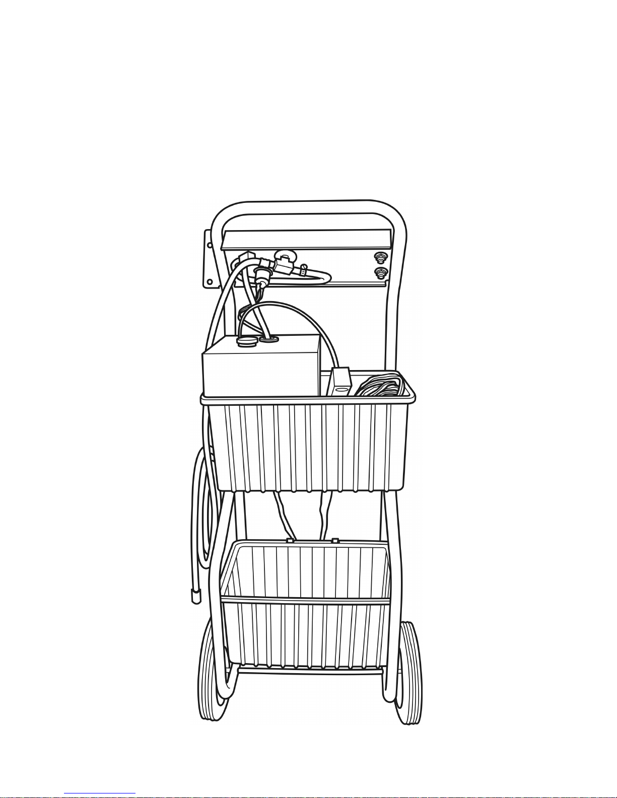
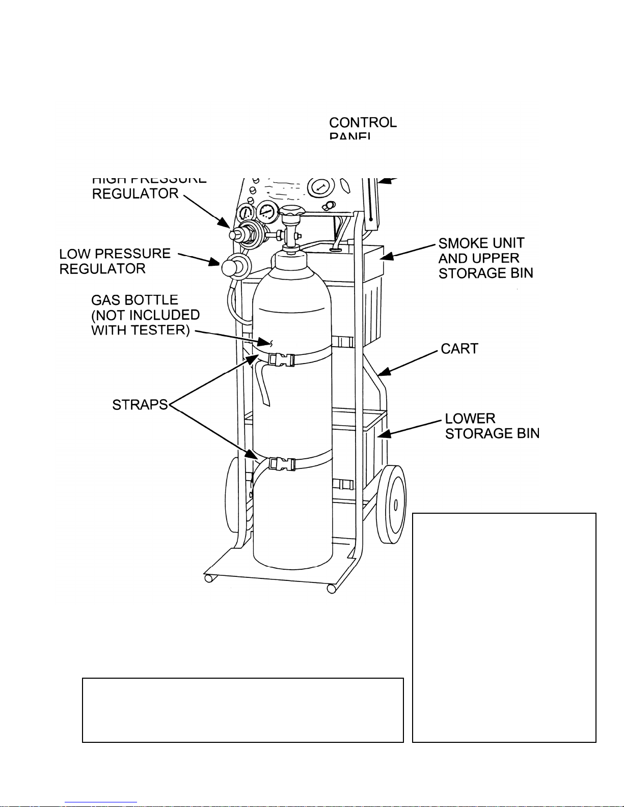
Fig. 1 - Front view
UNPACKING & SETUP
The KLI9210 Evaporative Emissions System
Tester ships with all the necessary adapters,
Flow Meter, regulators and the Smoke
Generation Unit plus any additional accessories
that were ordered with the unit.
1. Remove all items from the shipping boxes.
You should find the following:
Included Items:
EVAP Smoke Generator with cart –
Part # 44KLI9210
Test kit – Part # 45-10000-AD, including:
2 exhaust cones (prt # 4410000-122), cap plug kit (prt #
4410000-106), smoke diffuser (prt # 4410000-121) and
threaded nozzle adapter (prt # 4410000-102).
Threaded cap adapter – Part #. 4410000-80
Threaded cap receiver – Part # 4410000-81
Vehicle cap test hose – Part # 4410000-82
12-VDC halogen light – Part # 4410000-100
See page 14 for additional accessories.
2. Tester arrives almost fully assembeled. Store any adapters,
light and other accessories included with the Tester in
lower storage bin (fig. 1).
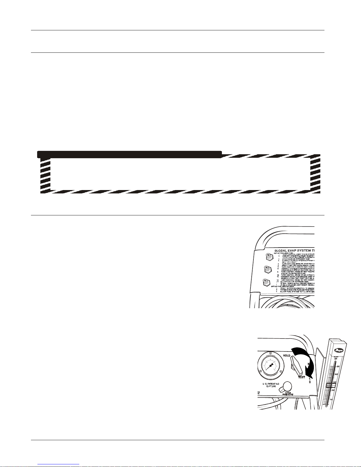
3. Make sure that the slots on both storage bins are seated on
the cart brackets provided. The entire edge of the plastic bin
should fit over the hanging bracket with the 2 tabs sticking
through the holes in each bin. (fig. 2).
IMPORTANT INFORMATION:
Read Before Operating Unit!
The smoke generation unit supplied with the KLI9210 is fully tested at the factory, drained and shipped with-out fluid in
unit. Prior to use, the smoke generation unit must be filled with smoke generation fluid supplied with unit. Completely
drain the fluid container into the smoke generation unit filler neck and dispose of the container according to your local/state
requirements.
It’s important to check the solution level and top off to the “Full” mark on the dipstick regularly,
just as you would regularly check the oil level of a car’s engine.”
TAB
OIL FILL TUBE