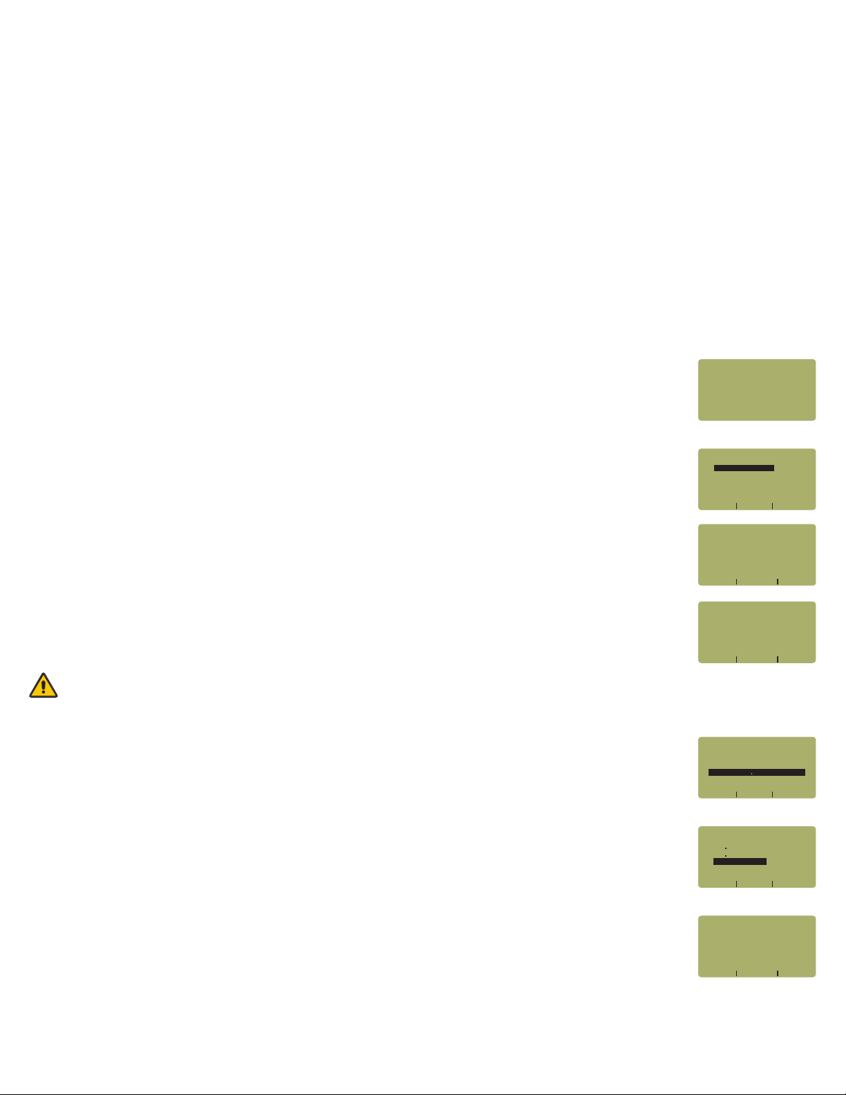
STEP 22 Enter the number of connections (i.e. patch panels) in the link under test. Typical fiber
networks will have 2 connections – one for a patch panel located at each end of the link.
Press <DONE> to continue.
STEP 23 Enter the number of splices in the link under test. Splices can be either fusion or mechanical. Typical
singlemode networks will have zero splices.
NOTE: some connectors use mechanical splice technology for termination. If the link under
test is terminated with these “no-polish, no-epoxy” type connectors, they should be considered
as mechanical splices.
Press <DONE> to continue.
STEP 24 Review your Link Wizard setup.
If correct, press <F1> and continue on to the next step.
If changes need to be made, press <F3> and go back to STEP 17.
STEP 25 Press <F1> until the asterisk (*) is in front of 1310nm (as shown at right).
Press <F2> to begin the SET REFERENCE procedure for 1310nm.
STEP 26 Connect the detector meter and 1310nm light source (left-hand port) together with
the singlemode cable as shown in Figure 2.
Press <F1> to continue.
STEP 27 Make sure that the 1310nm light source port is powered ON and selected (the indicator LED on the left-
hand side will be lit).
STEP 28 Confirm setting the 1310nm reference.
Pressing <F1> to continue. You will be returned to the SET SOURCE REFERENCES screen.
NOTE: if you are also testing at 1550nm, you will need to connect a separate singlemode patch cable to the
1550nm port.
STEP 29 For setting a 1550nm reference, repeat steps 25 through 28, except you will select
1550nm (as shown at right). Also make sure that you set the Laser OWL to 1550nm (the right-hand
indicator LED will be lit).
After the 1550nm reference is set, the REF dBm field will be filled in with a reference value.
STEP 30 Press <F3> to complete the Link Wizard.
STEP 31 Press <F1> to begin taking readings.
TAKE READINGS
STEP 32 Disconnect the singlemode patch cable from the Micro OWL 2 and take the units to opposite ends of
the link.
Do NOT disconnect the patch cable(s) from the light source at any time until all fibers have been tested.
1310nm
DONE
SOURCE
CONNECT
_____________________
WAVELEN REF dBmX X
---------------------
*1310nm NOT SETX X
X XXXX XXXX XWAVE SET DONE
X X X1550nm NOT SET
XXXXXXXXXXXXXXXXXXXXX
SET REFERENCESX
_____________________
(A CONNECTION IS WHENX X X
TWO FIBER CONNECTORSX X X
MATE USUALLY A PATCHXX X X
x XXX XXX X<--- SHIFT --->
PANEL)XXXXXXXXXXXXXXX
[2 ]X XXXXXXXXXXXXXXXXX
INLINE CONNECTIONS?X XX
_____________________
SPLICES IN THE FIBERX X X X
BEING TESTED:X XXXXXXXX
XXXXXXXXXXXXXXXXXXXXX
x XXX XXX X<--- --->SHIFT
XXXXXXXXXXXXXXXXXXXXX
[0 ]X XXXXXXXXXXXXXXXXX
ENTER THE NUMBER OFX X X XX
_____________________
01000 Metersx xxxxxxxxx
02 Connectionsx xxxxxxx
00 Splicesx xxxxxxxxxxx
X XXXXXXXXXXXXX XXYES NO
62 5um MMx x
IS THIS CORRECT?X X XXXXX
TIA-568-B 3X XX
_____________________
Standard »
Length »
Connections »
Splices »
Fiber Type »
XX1310nm
X XXXXXXXXXXXXX XXYES NO
xxxREF?
_____________________
xxxSET
WAVELEN REF dBmX X
---------------------
xX X x1310nm -20 00
X XXXX XXXX XWAVE SET DONE
*1550nm NOT SETX X
XXXXXXXXXXXXXXXXXXXXX
SET REFERENCESX
_____________________