BATTERY LED
The Battery LED is a multi-color LED that indicates the battery status.
CHARGE STATUS LED
The Charge Status LED is a multi-colored LED that indicates the charge status
of the device.
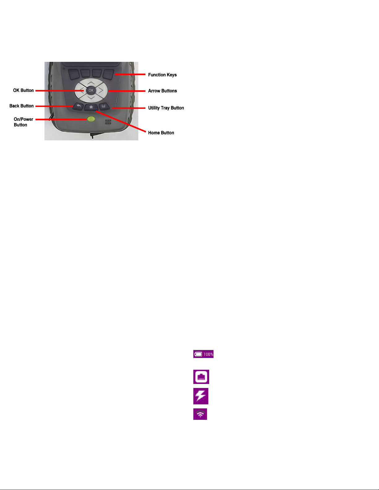
DEVICE CONTROLS
The front panel controls are used to operate and control the device.
OK BUTTON
The OK Button is used to confirm a setting or close a window.
HARD KEYS
The Hard Keys select screen-specific options or to select menus associated
with each key.
BACK BUTTON
The Back Button is used to exit a menu or to go back to the previous menu or
screen.
POWER BUTTON
The Power Button is used to turn the device on or off.
ARROW BUTTONS
The Arrow Buttons are used to navigate the UI.
UTILITY TRAY BUTTON
Pressing the Utility Tray Button opens the Utility Tray which contains buttons
that access system functions.
HOME BUTTON
Pressing the Home Button returns to the device’s home screen.
PREPARATION FOR USE
Perform the following when the device is received from the factory:
•Unpack the device and battery. Store packing material and shipping container
for possible future use.
•Install the battery (refer to the CX100 ComXpert Operation Manual for the
battery installation procedure).
•Verify shipment is complete in accordance with packing list. Report any
discrepancies to VIAVI.
•The CX100 is shipped from the factory with a protective film in place over the
LCD. Remove the protective film from the LCD before use.
POWERING THE DEVICE
The CX100 is designed to be powered by an internal battery or an external AC
power supply.
To Connect the Device to an AC Power Supply
1Connect the power cord to the AC Adapter/Charger.
2Connect the DC connector to the device’s DC input connector.
3Connect the power cord to a grounded AC power supply.
To Charge the Battery
1Connect the device to a grounded AC power supply.
2Verify the device’s Battery LED turns Amber to indicate the battery is
charging.
3The Battery LED turns green when the battery is fully charged.
POWER ON/OFF PROCEDURES
To Turn the Device ON
1Press and release the Power Button.
2An initializing indicator screen is displayed during the boot-up process. Wait
while the device completes the boot-up process; this takes ~ 30 seconds.
3The Home Screen is displayed when the device is ready for use.
To Turn the Device OFF
1Press and hold the Power Button for ~ 3 seconds. Release the Power
Button when the Front Panel LEDs begin to flash.
VERIFY OPERATION - DEVICE SELF TEST
The following procedure is used to verify that the CX100 is operating properly; the
procedure is not intended to verify that the CX100 is operating to specified
performance parameters.
1Power on the device.
2Verify the Front Panel LEDs flash on and off in a series of red and green
during the boot-up process.
3When the device is ready for use, verify the Front Panel Battery LED
Indicator is illuminated.
4When the display loads, select the RF Instrument menu.
5Select the AutoTest button.
6Select the File Field located at the top of the screen.
7Select Self Test from the test list.
8Press the Select All Soft-key.
9Press the Run Selected Soft-key.
10 Wait while the device performs a series of automated test process. Do not
interrupt this process of the self test will fail. Status indicators show when self
test is finished.
11 When AutoTest is finished, verify all portions of the test have passed. If any
portion of the AutoTest fails, please contact VIAVI for technical assistance.
CONTROL AND OPERATION
The Liquid Crystal Display (LCD) is a capacitive, touch screen that supports
gestures such as press to open/select/activate, press and hold, drag and drop,
swipe sideways and pinch to zoom.
UI LAYOUT
The User Interface (UI) is designed to be intuitive and easy to use. The CX100’s
screen layout and screen content changes based on factors such as the
selected function, user settings and modes of operation. Most screens consist
of a Header Bar, the Main Display area, and a Footer area.
HEADER BAR
The Header Bar displays system indicators and the Utility Tray Button which is
used to access device tools and functions.
MAIN DISPLAY AREA
The Main Display area contains a variety of components depending on the
selected function. The area may contain a list of collapsible menus/panels, plot
fields, or data tables.
FOOTER AREA
When present, the Footer area contains either a Shortcut Area or a Soft-key
Panel. The Shortcut Area is used to provide quick access to frequently used
functions. Soft-key panels contain controls and functions associated with the
active test function.
UI INDICATORS
The following indicators are commonly used system functions. Refer to the CX100
ComXpert Operation Manual for information about device UI indicators not
described in this guide.
TECHNICAL ASSISTANCE
Contact the Technical Assistance Center (TAC) for technical support or with any
questions regarding this or other VIAVI products.
Phone: 1-844-GO-VIAVI
For the latest TAC information, go to:
http://www.viavisolutions.com/en/services-and-support/support/technical-
assistance
Fig. 5 CX100 Front Panel Controls
The Battery Status Indicator displays the charge level of the
device’s internal battery. The charge level is also displayed as a
percent next to the indicator.
The Network Connection Indicator is displayed when the device
is connected to an active LAN.
The AC Power Indicator is displayed when the device is
connected to an AC power supply.
The WiFi Indicator is displayed when the device is connected to a
WiFi network.


