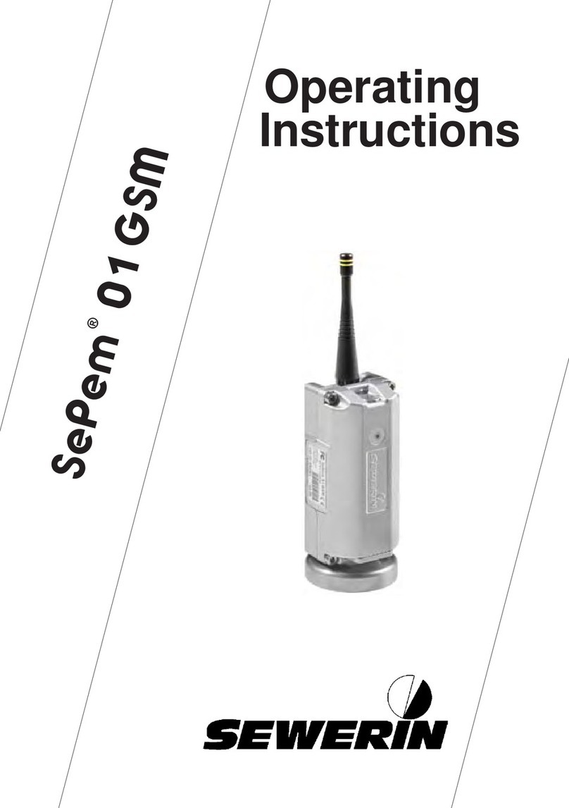
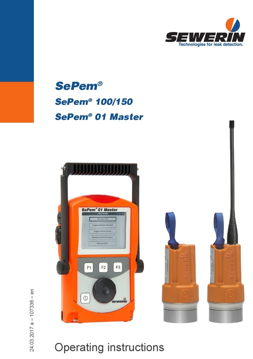
sewerin SePem Series User manual

30.08.2016 a – 107541 – en-us
SePem®
SePem®155
SePem®01 Master
Operating instructions

Antenna
Bar with loop
Antenna connector
Activation switch
Magnet
Fig. 1: SePem 155 Logger without antenna (top) and with antenna (bottom)
SePem®155 Logger

Connector
Buzzer
ON/OFF key
Antenna
Function keys F1, F2, F3
Fig. 2: SePem 01 Master without antenna (top) and withantenna (bottom)
Signal light
Display
USB port
Power supply port
Jog dial
Supporting bracket
SePem® 01 Master

Information about this document
The warnings and notes in this document mean the following:
ACAUTION!
Risk of personal injury. Could result in injury or health
risk.
NOTICE!
Risk of damage to property.
Note:
Tips and important information.
Enumerated lists (numbers, letters) are used for:
●Instructions that must be followed in a certain order
Lists with bullet points (point, dash) are used for:
●Lists
●Instructions that only invlove one step
Numbers enclosed by forward slashes /.../ refer to referenced doc-
uments.

I
Contents Page
1 Introduction .............................................................................1
2 General.....................................................................................2
2.1 Warranty....................................................................................2
2.2 Intended use .............................................................................2
2.3 General safety information ........................................................3
2.4 Notes on the radio operator’s license........................................3
3 SePem system.........................................................................4
3.1 System components..................................................................4
3.2 Mobile operation as an alternative to stationary operation........4
3.3 Operating principle ....................................................................4
3.3.1 Monitoring procedure (overview)............................................4
3.3.2 Data transmission ..................................................................5
3.3.3 Principles of leak detection ....................................................6
3.3.3.1 Leak detection in mobile operation .....................................6
3.3.3.2 Leak detection in stationary operation ................................6
4 SePem 155 Logger ..................................................................7
4.1 Function and setup....................................................................7
4.2 Specifying a device number (optional) ......................................7
4.3 Preparing the Logger for use ....................................................8
4.3.1 Screwing on the antenna .......................................................8
4.3.2 Manually activating the Logger ..............................................8
4.3.3 Pairing the radio frequencies .................................................9
4.3.4 ProgrammingtheLoggerforthersttime............................10
4.4 Installing the Logger at the measurement location ................. 11
4.4.1 Suitable installation locations ............................................... 11
4.4.2 Distance between two Loggers (recommended).................. 11
4.4.3 Installing the Logger.............................................................12
5 SePem 01 Master...................................................................13
5.1 Function and setup..................................................................13
5.2 Using the Master in vehicles ...................................................14
5.3 Power supply...........................................................................14
5.3.1 Options.................................................................................14
5.3.2 Special features of rechargeable batteries...........................15
5.3.3 Changing the batteries .........................................................15
5.3.4 External power supply..........................................................16

II
Contents Page
5.4 Operation ................................................................................17
5.4.1 Keys and jog dial..................................................................17
5.4.2 Standard functions ...............................................................18
5.4.3 Warning prompts..................................................................18
5.4.4 Enter text..............................................................................19
5.4.5 Scrolling in charts.................................................................21
5.5 Firmware menus and Master - Logger interaction ..................22
5.5.1 Main menu (overview)..........................................................22
5.5.2 Patrol....................................................................................23
5.5.2.1 Requirements for a successful patrol................................24
5.5.2.2 Patrol procedure (overview)..............................................25
5.5.2.3 Analysis of measuring result readings ..............................26
5.5.2.4 Extended data set .............................................................27
5.5.2.5 Graphics............................................................................29
5.5.3 Logger communication.........................................................31
5.5.3.1 MultipleLoggers(Loggerconguration)............................32
5.5.3.2 Single Logger....................................................................36
5.5.3.3 Transferring data to the Loggers.......................................39
5.5.3.4 Standard settings ..............................................................42
5.5.3.5 Frequency pairing .............................................................43
5.5.4 Logger management ............................................................44
5.5.4.1 Logger database ...............................................................44
5.5.4.2 Patrol lists..........................................................................47
5.5.5 Master settings.....................................................................48
5.5.6 Master info ...........................................................................51
6 Troubleshooting ....................................................................52
6.1 Problems with the Logger .......................................................52
6.2 Problems with the Master........................................................52
6.3 Problems with the Master - Logger radio connection..............53
6.3.1 Checking the radio connection.............................................53
6.3.2 Improving the radio connection ............................................55
6.4 Other problems .......................................................................55
7 Appendix................................................................................56
7.1 Specicationsandpermittedoperatingconditions..................56
7.1.1 SePem 155 Logger ..............................................................56
7.1.2 SePem 01 Master ................................................................57
7.2 Radio frequencies ...................................................................59
7.3 Measurement types (overview) ...............................................60
7.4 Menu structure ........................................................................61

III
Contents Page
7.5 Display symbols (Master)........................................................62
7.6 Terminology and general abbreviations ..................................64
7.7 Abbreviationsinthermware..................................................66
7.8 Accessories.............................................................................67
7.9 FCC/IC Compliance Statements .............................................68
7.10 Advice on disposal ..................................................................68
8 Index.......................................................................................69

1 Introduction│ 1
1 Introduction
The SePem system is used for the early detection of leaks in
water pipe networks.
The SePem 155 Logger is especially designed for stationary
operation, i.e. for continuously monitoring water pipe networks
atxedmeasurementlocationsoverlongperiodsoftime(sev-
eral years).
The SePem 01 Master programming and read-out unit allows
the system to be operated without the need for a computer.
SePem is a prelocation system. Indications that a leak is present
must,therefore,alwaysbeveriedusinganappropriatemethod
(e.g. correlation).
Note:
These operating instructions explain the SePem system. All de-
scriptions refer to the device as delivered (factory settings). The
manufacturer reserves the right to make changes.

2 │2General
2 General
2.1 Warranty
The following instructions must be complied with in order for any
warranty to be applicable regarding functionality and safe oper-
ation of this equipment.
●Read these operating instructions prior to operating the prod-
uct.
●Use the product only as intended.
●Repairs and maintenance must only be carried out by special-
ist technicians or other suitably trained personnel. Only spare
parts approved by Hermann Sewerin GmbH may be used
when performing repairs.
● Changesormodicationstothisproductmayonlybecarried
out with the approval of Hermann Sewerin GmbH.
●
Use only Hermann Sewerin GmbH accessories for the product.
Hermann Sewerin GmbH shall not be liable for damages result-
ing from the non-observance of this information. The warranty
conditions of the General Terms and Conditions (AGB) of Her-
mann Sewerin GmbH are not affected by this information.
In addition to the warnings and other information in these operat-
ing instructions, always observe the generally applicable safety
and accident prevention regulations.
The manufacturer reserves the right to make technical changes.
2.2 Intended use
SePem is a measurement data recording and evaluation system.
The system is designed for use in the stationary and mobile mon-
itoring of water pipe networks. The system must only be operat-
edbysuitablyqualiedemployees(skilledstaff,specialistsand
technicians) of water supply companies.
This system is only suitable for use in industrial and commercial
applications. All applicable safety and accident prevention regu-
lations must be complied with when using the system.
Detailed information on appropriate operating conditions for the
components of the system at the place of installation are provid-
ed in Section 7.1.

2 General│ 3
2.3 General safety information
This product was manufactured in accordance with all binding
legal and safety regulations. It corresponds to the state of the art.
The product is safe to operate when used in accordance with the
instructions provided.
However, if you handle the product improperly or not as intended,
the product may present a risk to persons and property. For this
reason, always observe the following safety information.
●Do not modify the product.
●Never open the Logger housing.
●
The Logger contains a powerful magnet. Keep the Logger
away from magnetic storage media (e.g. hard drives, credit
cards) and medical devices (e.g. pacemakers, insulin pumps).
●
The batteries in the Logger may only be replaced by SEWERIN
Service or by other suitably trained personnel.
●Ensure that no dirt or moisture gets into the connections on
all the devices.
●Never carry a unit by its antenna.
●Never bend, kink or cut the antenna of the devices.
●Always observe the permitted operating and storage tempera-
tures.
●Do not expose the SePem 01 Master to any source of mois-
ture that could get into the device.
2.4 Notes on the radio operator’s license
The SePem system may only be operated with a radio operator’s
license issued by the responsible authorities.
●Apply for a radio operator’s license before starting up the sys-
tem.
●Perform a frequency pairing with the assigned frequency (fre-
quency pair) before starting up the system.

4 │3SePemsystem
3 SePem system
3.1 System components
The SePem system (SePem for short) comprises:
●SePem 155 Logger, for short: Logger (see Section 4)
for recording measurement data
●SePem 01 Master, for short: Master (see Section 5)
for programming Loggers and collecting and evaluating mea-
suring results
A single Master can be used to manage up to 400 Loggers. A
wide range of accessories is available for the Loggers and the
Master (see Section 7.8).
3.2 Mobile operation as an alternative to stationary operation
The aim of stationary applications is to provide permanent mon-
itoring over a large area, whereas mobile applications of the sys-
tem are aimed at regular checks carried out over smaller areas.
Mobile operation represents a cost-effective alternative to sta-
tionary operation as only a limited number of Loggers are nec-
essary. The Loggers will typically be installed for a few days to
provide comprehensive coverage in the monitoring area. The
measurement data that is recorded can then be read out and
evaluated at regular intervals. Monitoring of the area is completed
when any leaks detected are repaired. The Loggers can then be
moved to the next monitoring area.
3.3 Operating principle
3.3.1 Monitoring procedure (overview)
The monitoring function is carried out as follows:
1. Prepare the Loggers (see Section 4.3)
2.
Install the Logger at the measurement location (see Sec-
tion 4.4.3)
The Loggers then work automatically, i.e. they record measure-
mentdataatthepredenedtimes.

3 SePem system│ 5
3. Read out the measuring results using the Master (see Sec-
tion 5.5.2)
The Logger will transmit the measuring results at regular in-
tervals within a prescribed period of time. The period of time
isreferredtoastheradiotimeframeandisspeciedduring
programming.
The operator must transport the Master to within the transmis-
sion range of the Logger to read out the data. The measuring
results will be transferred automatically from the Logger to
the Master as soon as the user enters the radio transmission
range.
It is also possible to display a graph of the measurement
(Graphics) and the Logger data.
4.
Evaluate the measuring results with the Master (see Sec-
tion 5.5.2.2 - Section 5.5.2.4, Section 5.4.4)
3.3.2 Data transmission
The Master and Logger communicate with each other by bidi-
rectional radio. The Master transmits and receives on a certain
frequency, the Loggers transmit and receive on another frequen-
cy. Together, the two radio frequencies form a frequency pair. All
the available frequency pairs are listed in Section 7.2.
Note:
Observe the information about the radio operator’s licence in
Section 2.4.
When installed in a pit, the Logger transmits its data out of that
pit. The range of the radio signals is heavily dependent on the
shielding effects of the shaft, especially the cover.
As a general rule, the radio signals can be expected to have a
range of 30 – 70 m (98 – 230 ft) from the installation position.
The range can be extended to 100 - 200m (328 – 656 ft) with
plastic covers.

6 │3SePemsystem
3.3.3 Principles of leak detection
Various techniques are used for leak detection.
Note:
Leak alerts will not be issued if there is background noise (fre-
quency 60 Hz or 120 Hz).
Please refer also to the information on interpreting measuring
results and leak alerts in Section 5.5.2.3 - Section 5.5.2.5.
3.3.3.1 Leak detection in mobile operation
In order to determine whether or not the measurement data re-
corded by a Logger used as a mobile unit indicates a leak, an
alarmthresholdisspeciedintheMaster (absolute value). If the
minimumnoiselevelmeasuredexceedsthespeciedthreshold
value then the operator will be alerted to a leak.
The level that is set for the alarm threshold will depend on the
material of the pipe in the vicinity of the Loggers. It is therefore
possible to set the alarm threshold in the Master for each indi-
vidual Logger.
3.3.3.2 Leak detection in stationary operation
When the system is used as a stationary application, leak de-
tection is based on a mathematical relationship that compares
measurement values at different points in time (detection of vari-
ations). The following points must be taken into consideration
when evaluating results:
●
The water pipe network must be leak-free before setting up the
system for stationary use.
●
Only leaks that occur after the monitoring has been started
will be detected.
●A leak alert will only be issued after three measurements have
beentakensincetherstoccurrenceoftheleak;thisavoids
falsedetectionofleaksduetoshort-termuctuations.
●
It is possible that false leak alerts may be issued (e.g. as a
result of prolonged heavy rain).

4 SePem 155 Logger│ 7
4 SePem 155 Logger
4.1 Function and setup
SePem 155 is a noise logger. It can acquire and save measure-
ment data from water pipe networks. Data is exchanged with the
Master by radio.
For an overview including the part names of the Logger, see the
frontcoverap(g.1).
Loop
A safety rope can be attached to the loop so that the Logger can
be easily installed and removed at underground locations.
Mounting
The unit can be mounted on metal objects using magnets. If it
is necessary to monitor a plastic pipe, then the Logger must be
attachedtothettings.
Power supply
The power supply is provided by a permanently installed lithium
battery that has a guaranteed lifetime of several years under
normal operating conditions.
4.2 Specifying a device number (optional)
Every Logger is assigned an 11 digit serial number by the manu-
facturer before shipping. In order to simplify the job of managing
the Loggers (in the Master software and at the measurement
location), it is possible to assign each unit a device number. Any
number may be selected, up to a maximum of four digits. This
number could, for example, be the same as the last four digits
of the serial number.
1. It is advisable to decide on a format that can be used as the
device number for all Loggers.
2. Each Logger should be labelled with the device number.
3. The device numbers must be saved with the corresponding
serial number in the Master (see Section 5.5.4.1).

8 │4SePem155Logger
4.3 Preparing the Logger for use
The preparatory work required for each Logger includes:
●Attaching the antenna to the Logger
●Pairing the radio frequencies
● ProgrammingtheLoggerforthersttime
4.3.1 Screwing on the antenna
The Logger and antenna are connected using a TNC connector.
The antenna can be screwed directly into the threaded antenna
connector.
1. Make sure that the contacts on the Logger and the antenna
are dry and clean.
2. Screw the antenna onto the antenna connector.
Securely tighten the antenna by hand to ensure that the unit
is sealed and to guarantee a good radio connection.
NOTICE! Risk of damage
The internal contacts of the TNC connector must not be subject-
ed to mechanical load.
●Only tighten the antenna by hand.
●Do not use tools.
4.3.2 Manually activating the Logger
Loggers can be activated manually to establish a radio connec-
tiontoaspecicMaster .
Manual activation is required for the frequency pairing and pro-
grammingforthersttimeetc.
●Move a magnet over the activation switch.
−You can use, for example, the magnet from another Logger.
−Fig. 3 shows the direction in which the magnet has to move.

4 SePem 155 Logger│ 9
Note:
The Logger will remain ready to receive information for one min-
ute after activation. It can then be reactivated if necessary.
Fig. 3: Activating the Logger:
Relief of activation switch on housing (left)
Direction of movement of magnet (right)
4.3.3 Pairing the radio frequencies
To allow the Master and Logger to communicate successfully
with each other, the radio frequencies have to be set to a fre-
quency pair.
Note:
Observe the information about the radio operator’s licence in
Section 2.4.
1. Set the assigned frequency (License frequency) in the
Master under Master settings.
2. Select Frequency pairing from the Logger communi-
cation menu in the Master.
3. Press F1 Start Scan.
4. Activate a Logger (see Section 4.3.2).

10 │4SePem155Logger
5.
Wait until the Master has recognized the Logger and as-
signed it the new frequency. The Logger will then be listed
under SERIAL.
−
The Logger will remain ready to receive information for
one minute after activation. If the scan is not successfully
completed within this time, you will need to reactivate the
Logger again.
6. Activate another Logger. It will also appear in the list as soon
as it has been recognized.
Repeat this step until all the Loggers have been paired.
4.3.4 Programming the Logger for the rst time
Before installing the Logger at the measurement location it must
be programmed, i.e. data relating to measurement times, mea-
surement duration and the radio time frame etc. must be trans-
mitted from the Master to the Logger.
1. Prepare the Master for programming the Loggers (see Sec-
tion 5.5.3, in particular Section 5.5.3.1).
2. Activate the Logger (see Section 4.3.2).
3. Move the Master into the transmission range of the Logger.
Transfer the data (see Section 5.5.3.3).
If a radio connection is not established between the Master and
the Logger within the available time frame, then the Logger will
automatically switch off again and may need to be reactivated.
Note:
If the device settings for the Logger are changed in the course
of further work, then the radio time frame can be used to trans-
fer the relevant data. The Logger, therefore, does not have to be
activated manually every time.

4 SePem 155 Logger│ 11
4.4 Installing the Logger at the measurement location
4.4.1 Suitable installation locations
The Logger can be mounted on:
●Pipes
●Fittings
(slide gates, underground hydrants, above-ground hydrants)
Note:
Only attach the Logger to above-ground hydrants if it is possible
to protect the device against theft and vandalism.
The units can be installed in water pipe networks constructed
from both metal and plastic piping. Please note the following
points relating to plastic water pipe networks:
●The Logger cannot be mounted directly on the pipe, instead it
hastobeattachedtoatting.
●
Sound is not transmitted through plastic piping as well as
through metal pipework systems.
4.4.2 Distance between two Loggers (recommended)
The following spacing is recommended between each Logger to
allow systematic monitoring of an area:
Water pipe
material
Logger
location
Recommended distance
between two Loggers
Metal Fitting 300 – 500 m (984 – 1640 ft)
(mobile)
500 m (1640 ft) (stationary)
Plastic Fitting 50 – 100 m (164 – 328 ft)
For highly intermeshed water pipe networks, the distance be-
tween Loggers may have to be reduced accordingly.

12 │4SePem155Logger
4.4.3 Installing the Logger
TheLoggerisxedintopositionattheinstallationlocationusing
the magnet.
Note:
Please see Section 4.4.1 and Section 4.4.2!
NOTICE! Damage possible due to careless positioning
The Logger contains sensitive parts.
●Always position the Logger on the attachment point with care.
Installation instructions
●
Use a safety rope if the attachment point is so far underground
that you cannot position the Logger by hand. The safety rope
is attached to the loop.
The safety rope is available to buy as an accessory.
●Ensure that a good metal-to-metal contact is formed between
the Logger magnet and the attachment point.
It is important that structure-borne sound is not damped by dirt,
mud or rust. Clean the attachment point if necessary before
mounting the Logger magnet.
●
The antenna of the SePem 155 must not touch any metal parts
at the installation location.
●The antenna of the SePem 155 must remain straight after the
shaft cover is closed and must not come into contact with the
installation location. Allow the necessary clearance.

5 SePem 01 Master│ 13
5 SePem 01 Master
5.1 Function and setup
The Master is the programming device and reader for the Log-
gers.
The following tasks can be performed using the Master:
●Program the Loggers
●Read out measuring results and device data from the Loggers
●Evaluate the measuring results (including chart)
●Change Logger data
An illustration of the Master with all parts labelled is provided on
the inside front cover.
Antenna
The Master antenna guarantees a reliable bidirectional radio
connection between the device and the Loggers. This is import-
ant because all measurement data, device data and program
-
ming data for the Loggers is transmitted using radio signals.
Supporting bracket
The supporting bracket can be used for carrying the unit and as
a stand. The supporting bracket can be adjusted to different po-
sitions. With the bracket turned to the rear of the unit, the Master
can be stood up safely in a convenient position for reading the
display.
Display illumination
The duration for which the display is illuminated can be adjusted.
The light will come on whenever a key is pressed or the jog dial
ismoved(exceptwhenbatteryisalmostat).
Memory
The Master saves the measuring results in a ring memory. This
means that when the memory is full, i.e. when there is no more
storage space available, the oldest data is automatically overwrit-
This manual suits for next models
2
Table of contents
Other sewerin Data Logger manuals
