sewerin Sepem 01 GSM User manual

Operating
Instructions

Measurable success by Sewerin equipment
Congratulations. You have chosen a quality instrument manufactured
by Hermann Sewerin GmbH.
Our equipment will provide you with the highest standards of perfor-
mance, safety and efciency. They correspond with the national and
international guide-lines.
Please read and understand the following operating instructions before
usingtheequipment;theywillhelpyoutouse theinstrumentquicklyand
competently. If you have any queries we are available to offer advice
and assistance at any time.
Yours
Hermann Sewerin GmbH
Robert-Bosch-Straße 3
33334 Gütersloh, Germany
Tel.: +49 5241 934-0
Fax: +49 5241 934-444
www.sewerin.com
info@sewerin.com
Sewerin Ltd
Hertfordshire
UK
Phone: +44 1462-634363
www.sewerin.co.uk
info@sewerin.co.uk
SEWERIN Sarl
17, rue Ampère - BP 211
67727 HOERDT CEDEX, France
Tél. : +33 3 88 68 15 15
Fax : +33 3 88 68 11 77
www.sewerin.fr
sewerin@sewerin.fr
SEWERIN IBERIA S.L.
c/ Cañada Real de Merinas, 17
Centro de Negocios „Eisenhower“
Edicio 5; Planta 2 - C
28042 Madrid, España
Tel.: +34 91 74807-57
Fax: +34 91 74807-58
www.sewerin.es
info@sewerin.es
PO Box 247
Saint James, MO 65559
Phone: +1 800-526-5246
Fax: +1 800-807-9368
www.edenbros.com
EDENBROS, LLC

SePem 01 GSM
Aerial
LED and magnetic switch
SIM card cover
Magnet
Aerial connector
Guide rail for alternative magnetic
attachment
Retaining nut, sliding
(dependent on ttings supplied)
Fig. 2: SePem 01 GSM without antenna (viewed from above and the side)
Fig. 1: SePem 01 GSM with aerial
Jack socket with screw plug

SePem 01 Interface
USB connector
Fig. 3: SePem 01 Interface
LED, green (power supply)
LED, red (data transfer)
Jack socket

Operating Instructions
10.11.2008 – V 1.X – 105765 – en
SePem®01 GSM

Used symbols
CAUTION!
This symbol is used to indicate dangers which may
eitherresultinhazardsfortheoperatorsorinsevere
damage – or even destruction – of the product.
Note:
This symbol is used to call attention to information
andtipswhichmaybehelpfulandwhichareexceed-
ing the basic operating procedures.

I
Contents Page
1 Introduction .............................................................................1
2 General.....................................................................................2
2.1 Warranty....................................................................................2
2.2 Intended use .............................................................................3
2.3 Safety information .....................................................................4
3 Monitoring water pipe networks using the SePem 01 GSM5
3.1 Equipment required...................................................................5
3.2 Monitoring process (overview) ..................................................6
3.3 Data transmission .....................................................................7
4 GSM Logger - SePem 01 GSM ...............................................8
5 SePem 01 GSM Interface programming unit........................9
6 Preparing the GSM Logger for use......................................10
6.1 Inserting the SIM card .............................................................10
6.2 Programming the GSM Logger...............................................11
6.2.1 Equipment required..............................................................11
6.2.2 Preparing the device for programming.................................11
6.2.3 Changing the Logger settings ..............................................12
7 Installing the GSM Logger at the measurement.................13
7.1 Suitable attachment points......................................................13
7.2 Distance between two Loggers ...............................................13
7.3 Attaching the magnet and aerial to the GSM Logger ..............14
7.3.1 Magnet .................................................................................14
7.3.2 Aerial and aerial adapter ......................................................15
7.4 Mounting the GSM logger and testing the network connection.16
7.4.1 General installation instructions...........................................16
7.4.2 Installation procedure...........................................................17
8 Troubleshooting....................................................................19
8.1 Problems with the GSM Logger ..............................................19
8.2 Test SMS does not function correctly......................................20

II
Contents Page
9 Appendix................................................................................21
9.1 Specications and permitted operating conditions..................21
9.1.1 SePem 01 GSM ...................................................................21
9.1.2 SePem 01 GSM Interface ....................................................22
9.2 System requirements for computer .........................................22
9.3 Terminology and abbreviations ...............................................23
9.4 Accessories.............................................................................25
9.5 Firmware history......................................................................26
9.6 Declaration of conformity ........................................................27
9.7 Advice on disposal ..................................................................28
10 Index.......................................................................................29

1
1 Introduction
1 Introduction
The SePem 01 GSM is a logger that is able to both collect data
and to automatically transmit it to the receiver. Data is transmitted
using the digital mobile telephone network.
The SePem 01 GSM is designed for use in the early detection
of leaks in water pipe networks. The system is designed for
stationaryoperation,i.e.foruseincontinuousmonitoringof water
pipe networks at xed measurement locations over long periods of
time (several years). Generally, a large number of GSM loggers
are installed at the same time in order to provide monitoring over
a wide area.
The SePem 01 GSM isonlysuitable forthepreliminarydetection
of leaks. Indications that a leak is present must therefore always
be veried using an appropriate method (e.g. correlation).
The SePem 01 GSM is an enhanced version of the SePem 01
system, which requires an additional device to be used to read
out measurement data.

2
2 General
2 General
2.1 Warranty
The following instructions must be complied with in order for any
warranty to be applicable in respect of the functionality and safe
operation of this equipment.
HermannSewerinGmbHcannotbeheldresponsibleforanydam-
ages resulting from non-compliance with these instructions. The
warranty and liability provisions of the terms of sale and delivery
of Hermann Sewerin GmbH are not affected by the information
given below.
The product must only be operated after the relevant operating
instructions have been read and understood.
The product must only be used for its intended purpose.
The product is only suitable for use in industrial and commer-
cial applications.
Repairs must only be carried out by a specialist technician or
by other suitably trained personnel.
Changes or modications to this product must not be carried out
without approval from Hermann Sewerin GmbH. The manufac-
turer cannot be held responsible for damages if non-approved
modications have been made.
Only accessories supplied by Hermann Sewerin GmbH may
be used with this product.
All repairs must be carried out using replacement parts that
have been approved by Hermann Sewerin GmbH.
Only approved aerials may be used.
The manufacturer reserves the right to make technical modi-
cations in the course of further development.
Generally applicable safety and accident-prevention regulations
must be complied with, in addition to the information provided in
this manual.

3
2 General
2.2 Intended use
The SePem 01 GSM logger is used for the acquisition of mea-
surement data. The system is designed for use in stationary
monitoring applications for water pipe networks It must only be
operated by suitably qualied employees (skilled staff, specialists
and technicians) of water supply companies. The logger must only
be installed in shafts and underground hydrants.
The SePem 01 GSM Interface is used for programming the log-
ger. The device must only be operated using the cables supplied
(USB cable, connector cable).
All applicable safety and accident prevention regulations must
be complied with when operating the SePem 01 GSM and
SePem 01 GSM Interface.
Specic details of the operating conditions applicable to the op-
eration of the SePem 01 GSM and SePem 01 GSM Interface
at the measurement location are provided in the appendix (Sec-
tion 9.1)
The SePem 01 GSM and SePem 01 GSM Interface have been
manufactured in accordance with all statutory legal and safety
regulations. All components used correspond to the state-of-the-
art and conform to EC requirements. The devices are safe to op-
erate when used in accordance with the instructions provided.
4
2 General
2.3 Safety information
These operating instructions must be read carefully and in full. All
advice given in these operating instructions must be followed.
CAUTION!
All applicable accident prevention regulations must
be observed.
Do not carry out any modications to the SePem 01 GSM or
otherwise change or tamper with the device in any way. Never
open the device. Failure to observe the above instructions will
invalidate the warranty.
CAUTION! Hazardous to life and property.
The SePem 01 GSMcontainsapowerfulmagnet.
Persons with heart pacemakers must avoid
close proximity to the device.
The SePem 01 GSM must be kept away frommag-
netic storage media (diskettes, hard drives, credit
cards, etc.), monitors (PC, TV) and clocks.
The power supply for the SePem 01 GSM is provided by per-
manently installed lithium batteries. These batteriesmustonly
be replaced by SEWERIN Service.
Do not expose the SePem 01 GSM to temperatures above
70 °C.
The aerial on the SePem 01 GSM must not be damaged.
Never carry this type of unit by the aerial.
Never bend, kink or cut the aerial.

5
3 Monitoring water pipe networks using theMonitoring water pipe networks using the SePem 01 GSM
3 Monitoring water pipe networks using the
SePem 01 GSM
3.1 Equipment required
The following items are required for data acquisition using the
SePem 01 GSM system:
SePem 01 GSM, abbreviated to: GSM Logger (see Section 4)
for the acquisition, processing, buffering and transmission of
measurement data.
There is no limit on the number of GSM Loggers that can be
operated simultaneously.
A SIM card for each GSM Logger.
The SIM card is not supplied with the device. This must allow
the device to receive calls and send text messages. SIMs that
only provide data and facsimile connections cannot be used.
SePem 01 GSM Interface, abbreviated to: Interface(seeSec-
tion. 5) for programming the GSM Logger
SePem software
forprogramming the GSM Logger and evaluation of measure-
ment data.
The SePem software is explained in a separate set of ope-
rating instructions.
Computer
It is recommended that the connection between the GSM Log-
ger and the mobile phone network be tested during installation.
This requires:
A standard mobile phone

6
3 Monitoring water pipe networks using theMonitoring water pipe networks using the SePem 01 GSM
3.2 Monitoring process (overview)
The basic procedure for operating a SePem 01 GSM is as fol-
lows:
Insert the SIM card into the GSM Logger (see Section 6.1)
Program the GSM Logger at the computer using the
SePem software and the Interface (see Section 6.2)
Install the GSM Logger at the measurement location (see
Section 7)
The GSM Logger now operates autonomously, i.e. it acquires
data at the predened times.
Measurement results are sent automatically to the computer
via SMS.
Evaluate measurement results at the computer (see separate
operating instructions for SePem software)

7
3 Monitoring water pipe networks using theMonitoring water pipe networks using the SePem 01 GSM
3.3 Data transmission
The GSM Logger is tted with a module that provides data
transmission across the digital GSM mobile phone network. The
GSMmoduletransmitsmeasurementdataacquiredandbuffered
by the GSM Logger at predened intervals (e.g. once per day)
by means of an SMS This is converted to an e-mail by an SMS
e-mail gateway.
Requirements: E-mail connection
Advantages: Computer does not have to be switched
on permanently.
Fig. 4: Data transmission - receiving an e-mail
8
4 GSM Logger - SePem 01 GSM
4 GSM Logger - SePem 01 GSM
The SePem 01 GSM (abbr: GSM Logger is a noise logger. It is
able to acquire data from a water pipe network and to store this
data. Data exchange with the computer is via a mobile phone
network.
The robust, waterproof, die-cast aluminium housing means the
Logger issuitable for permanent installationinshaftsandunder-
ground hydrants.
The unit can be mounted on metal objects using the magnet. If
it is necessary to monitor a plastic pipe, then the GSM Logger
must be attached to the ttings.
An illustration of the GSM Logger with all parts labelled is pro-
vided on the inside front cover.
The power supply is provided by permanently installed lithium
batteries that have a guaranteed lifetime of several years under
normal operating conditions. (“Normal operating conditions” cor-
respond to the Default settings in the SePem software.)
CAUTION!
The GSM Logger mustneverbe openedbytheop-
erator. The unit will be prone to leakage if opened.
Used batteries must only be replaced through the
authorised SEWERIN Service scheme. There is a
risk of explosion and/or poisoning if batteries
are changed incorrectly.
A slotted nut driver must be used to remove the jack socket screw
plug (supplied with SePem 01 GSM Interface).
9
5 SePem 01 GSM Interface programming unit
5 SePem 01 GSM Interface programming unit
The SePem 01 GSM Interface (abbr.: Interface) is a program-
ming tool for the GSM Logger. The device allows data to be
transferred between the computer and the GSM Logger.
An illustration of the Interface with all parts labelled is provided
on the inside front cover.
The Interface is always connected between the GSM Logger
and the computer (see also Fig. 6).
Connection to the Interface Cable Connect to
USB USB cable Computer
Jack socket Cable with
jack plug GSM Logger
Note:
When the Interface is connected for the rst time,
the computer will usually recognise it as new hard-
ware. A message will be displayed prompting that
the corresponding device driver is required. The
driver can either be downloaded automatically
from the Internet or installed manually from the
SePem software CD.
Power is supplied to the device via the computer. The green LED
will light up as soon as power is available.
The red LED will ash when data is being transferred between
the computer and the logger.

10
6 Preparing the GSM Logger for use
6 Preparing the GSM Logger for use
6.1 Inserting the SIM card
Every GSMLoggermust be tted with a SIM card before it is used
for the rst time (not included with the device; see Section 3.1 for
requirements). The SIM card is necessary to identify the Logger
in the GSM network.
A Torx head screw driver is required for inserting the SIM card
(accessory).
Unscrew the cover.
Slide the SIM card into the slot, as shown in Fig. 5.
Fig. 5: Slide in the SIM card
Use a tool (e.g. screw driver) to push the SIM card down until
it locks into place.
Screw the cover back into place, being careful to ensure that
the seal is correctly positioned and does not get squashed.
Tighten the screws rmly.
11
6 Preparing the GSM Logger for use
6.2 Programming the GSM Logger
Each GSMLogger must rst be programmed before it is installed at
themeasurementlocation,i.e.datarelatingtomeasurementtime,
measurementduration,etc.mustbetransferredfromthecomputer
to the GSM Logger. The SIM data from the GSM Logger will be
recorded on the computer at the same time.
6.2.1 Equipment required
Programming requires the following items:
Interface
Computer with SePem software installed
USB cable, connector cable
A slotted nut driver for removal of the jack socket screw plug
on the GSM Logger
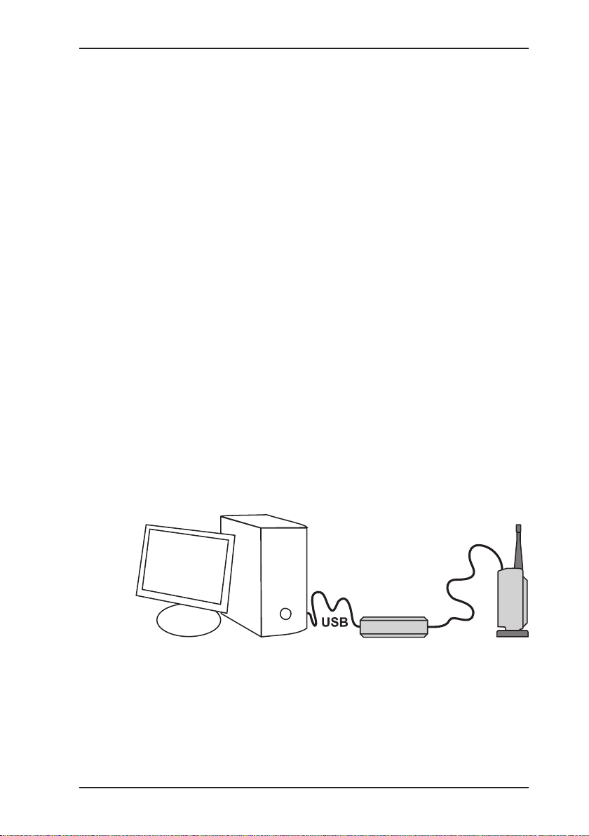
6.2.2 Preparing the device for programming
Undo the jack socket screw plug on the GSM Logger.
Connect the Interface to the computer using the USB cable.
Connect the GSM Logger to the Interface using the connec-
tor cable.
Fig 6: Programming a GSM Logger using an Interface (setup)
Launch the SePem Software on the computer.
Preparation is now complete. The steps to be carried out on the
computer for programming the GSM Logger aredescribedinthe
SePem Software operating instructions.

12
6 Preparing the GSM Logger for use
Note:
The jack socket screw plug must always be screwed
back into place once programming of the Logger is
complete. Tighten the screw rmly.
6.2.3 Changing the Logger settings
The GSM Logger settings can be changed at any time using
the SePem softwareand the Interface (see Section 6.2.2). The
GSM Logger must be removed from the measurement location
for this purpose.
Table of contents
Other sewerin Data Logger manuals


