Seyeon FlexWATCH FW3470 User manual

FW3470 User’s Manual
M4059-00 1 Seyeon Tech Co., L d
FW3470 User’s Manual
(Product Guide)
Version 4.12
Se tember 30, 2011
Class A Digital Device (industrial & commercial environment)
This equipment has been tested and found to comply with the limits for a Class A digital device, pursuant to CE and
FCC Rules. These limits are designed to provide reasonable protection against harmful interference when the
equipment is operated in a commercial environment. This equipment generates, uses and can radiate radio
frequency energy and, if not installed and used in accordance with the instruction manual, may cause harmful
interference to radio communications. Operation of this equipment in a residential area is likely to cause harmful
interference in which case the user will be required to correct the interference at his own expense.

FW3470 User’s Manual
M4059-00 2 Seyeon Tech Co., L d
FW3470 User’s Manual
Document Part Number: M4059-00
Document Version: 4.12
Revised: Se tember 30, 2011
About This Document
This document is re ared for users of FW3470 su lied by Seyeon Tech Co., Ltd. It is assumed that the
users are familiar with Microsoft Windows o erating systems and Web browsers such as Internet Ex lorer.
It is also assumed that the users are well aware of how to install and use the network equi ment such as
LAN, Hub, router, and having basic knowledge of network terminologies. If you have any questions
regarding network installations, lease contact your network equi ment vendor or network administrator
or Internet service roviders.
For u dated contents, detailed features and other a lications from Seyeon Tech, lease refer to the user’s
manual in CD-ROM rovided with the roduct you urchased, or visit Seyeon Tech’s Internet home age at
htt ://www.flexwatch.com/.
Copyright otice
Co yright © 2011 Seyeon Tech Co., Ltd. All rights reserved.
No art of this document may be re roduced in any form or by any means without the rior written
ermission of Seyeon Tech Co., Ltd.
Disclaimer
Seyeon Tech Co., Ltd. (Seyeon Tech) Makes no re resentations or warranties with res ect to the contents
hereof. In addition, information contained herein is subject to change without notice. Every recaution has
been taken in the re aration of this manual, nevertheless, Seyeon Tech assumes no res onsibility for
errors or omissions or any damages resulting from the use of the information contained in this document.
Trademarks
FlexWATCH
®
and FlexWATCH
®
Logo are trademarks of Seyeon Tech Co., Ltd.
Windows and Internet Ex lorer are a trademark of Microsoft Cor oration.
All other trademarks belong to their res ective owners.
Technical Support
For technical su ort call, email, or visit our web site.
Tele hone: +82-2-2192-6800
Email: [email protected]
Web site: htt ://www.flexwatch.com or htt ://www.seyeon.co.kr

FW3470 User’s Manual
M4059-00 3 Seyeon Tech Co., L d
Contents
1. PRODUCT OVERVIEW ......................................................................................................................... 4
1.1. FW3470 .......................................................................................................................................................................... 4
1.2. K
EY
F
EATURES
................................................................................................................................................................. 5
1.3. T
ECHNICAL
S
PECIFICATION
........................................................................................................................................... 6
1.4. FW3470
P
ACKING
L
IST
................................................................................................................................................ 8
2. PRODUCT DESCRIPTION .................................................................................................................... 9
2.1. FW3470
F
RONT
V
IEW
.................................................................................................................................................. 9
2.2. FW3470
R
EAR
V
IEW
.................................................................................................................................................. 10
2.2.1.
COM Port Description ...................................................................................................................................... 11
3. FW3470 INSTALLATION AND BASIC SETUP ................................................................................. 12
3.1. B
EFORE
I
NSTALLATION
................................................................................................................................................. 12
3.2. F
ACTORY
D
EFAULT
S
ETTINGS
..................................................................................................................................... 12
3.3. I
NSTALLING
FW3470 .................................................................................................................................................. 12

FW3470 User’s Manual
M4059-00 4 Seyeon Tech Co., L d
1. Product Overview
1.1. FW3470
FlexWATCH® 3470 is 1ch network video server which transmits digital images captured by Analog
CCD camera over IP(Internet Protocol) network.
It can transmit up to 30fps@D1 over the existing network. You can monitor video of FW3470 through
web browser(ie. MS Internet Explorer), if FW3470 is connected to network. FW3470 supports video
compression both Motion-JPEG and H.264 simultaneously so that user can choose appropriate video
compression for the purpose. For both Motion-JPEG and H.264, FW1174 provides 6 levels of video quality.
FW3470 server is state-of-the art device and leads new generation of monitoring and security solution.
Picture 1 : FW3470

FW3470 User’s Manual
M4059-00 5 Seyeon Tech Co., L d
1.2. Key Features
Standalone device with a built-in web server
10M/100M/1000M Auto-Sensing Ethernet
Configuring and controlling through Web browser
Max 30 fps transmission rate at D1 resolution in NTSC format on TCP/IP network
Effective Bandwidth & Bit-rate Control (VBR/CBR) by H.264
Supports Dual Streaming in Motion JPEG and H.264
Compressed audio transmission for each channels
Audio decoding for one channel
Support Dynamic IP network by IPCCTVDNS Server
Support various PTZ (Pan/Tilt/Zoom) devices
Provide Sensor Input and Digital Output
Provide Transparent Mode
Encryption on user authentication level
Image transmission via FTP and Email
Provide 4-Channel analog quad outputs

FW3470 User’s Manual
M4059-00 6 Seyeon Tech Co., L d
1.3. Technical Specification
Hardware
32bit Embedded CPU
Flash 8Mbytes /SDRAM: 128Mbytes
Linux version 2.6.24.4 operating system
Battery backed up real-time clock
Video
compression Motion JPEG
H.264
Resolution NTSC: 704x480,704x240,352x240,176x112
PAL: 704x576,704x288,352x288,176x144
Frame rate
(each channel) Motion JPEG: Up to 120 fps@D1
H.264: Up to 120 fps@D1
Video Streaming Motion JPEG and H.264 Dual Streaming (Simultaneously)
Controllable frame rate and bandwidth
Image setting Compression levels: 6 (MJPEG/H.264)
Color: color, black & white
Transmission Performance(1000Base-T / LAN)
Trans: Up to 120fps(NTSC)/100fps (PAL)
when 4channels at D1
Voice 4bit G.723, Sampling rates 8KHz Mono
Audio 4ch in & 1ch out
LAN interface 10/100/1000BaseT Ethernet auto sensing
Alarm I/O Interface 4x1 Photo-coupled inputs and 4 Relay output
Video Input 4 Channel Composite Video Input
Quad Output 1 Channel Quad Composite Video Output
Serial Interface
COM Port: RS-232
AUX Port: RS-485/RS-422
COM ports for console, serial input/output device and AUX ports for PTZ or
other RS485/422 device
Max Baudrate: 115200 bit/s
Security features Multi user level protection for camera access, PTZ, Alarm I/O
Advanced Service Up to 5.6M memory for Pre/Post alarm buffer e-mail, FTP, IP notification,
Alarm Notification to e-mail, CGI Call by event or schedule
Built-in Motion detections Accuracy: 12x12=144 blocks
Motion Sensitivity : -100 ~ 100 : 100 is hypersensitive
PTZ & UART Control Support
PTZ and UART device control through serial port (RS-232/RS-485) (Support
protocols from Pelco “P”& “D”protocol, Vicon V1311RB, Samsung PTZ,
Honeywell PTZ and X10 Epson Printer)
Others Time stamp on Video
Transmit External data(ex. POS) transfer with Video
IP notification by e-mail
Management Configurable by serial, web or telnet
Remote system update via telnet, FTP OR web browser.

FW3470 User’s Manual
M4059-00 7 Seyeon Tech Co., L d
Developer support Provides HTTP CGI API
ActiveX control development kit
PWR Supply SMPS
Input: 100~240VAC, 1.5A
Output: DC 12 Volt, 3 A, SMPS
PWR Consumption DC 12Volt
Max or Peak: 0.8 A
Normal : 0.7 A
Operating Environment Temperature : 32°~ 122°F (0°~ 50°C)
Humidity : 20 ~ 80% RH(non-condensing)
Miscellaneous Freely downloadable NDVR Software
Work with FW-Manager(NDVR S/W)
Dynamic IP support through IPCCTVDNS
Users 128 simultaneous users
Installation, management and
maintenance
Installation CD and web-based configuration
Configuration backup and restore
Firmware upgrades over HTTP or FTP , firmware available at
www.flexwatch.com
Video access from Web
browser Video access from Web browser
Minimum Web browsing
requirements
Pentium 4, 2 GHz, 2GB(RAM) or higher
Video Card: 256MB RAM, 1024x768 resolution or higher
100Mbps Network Adaptor or faster
Windows XP Pro or later
Internet Explorer 6.x or later
System integration support
Powerful API for software integration available at http://www.flexwatch.com,
including Simple Viewer API, FlexWATCH Control SDK, event trigger data in
video stream, embedded scripting and access to serial port peripherals over
HTTP/TCP
User can be installed user program daemon for event notification or sending
image.
Embedded operating system: Linux 2.6
Supported protocols HTTP, RTP/RTSP, TCP/IP, FTP, Telnet, RARP, PPPoE, PAP, CHAP, DHCP,
SMTP client(e- mail), NTP
Applications
(not included) FlexWATCH Manager 16/32/128/256
Included Accessories Power supply 12 V DC / Power cord
Terminal Blocks
CD (User’s Manual, installation wizard and etc)
Not included
Accessories 19”Rack Mount Bracket
Approvals
MIC
FCC
CE
RoHS
Dimensions (HxWxD) and
weight 240(W) x 224(D) x 44(H) (in mm)
About 1.62kg without power supply.
Table 1 : FW3470 Data Sheet
FW3470 User’s Manual
M4059-00 8 Seyeon Tech Co., L d
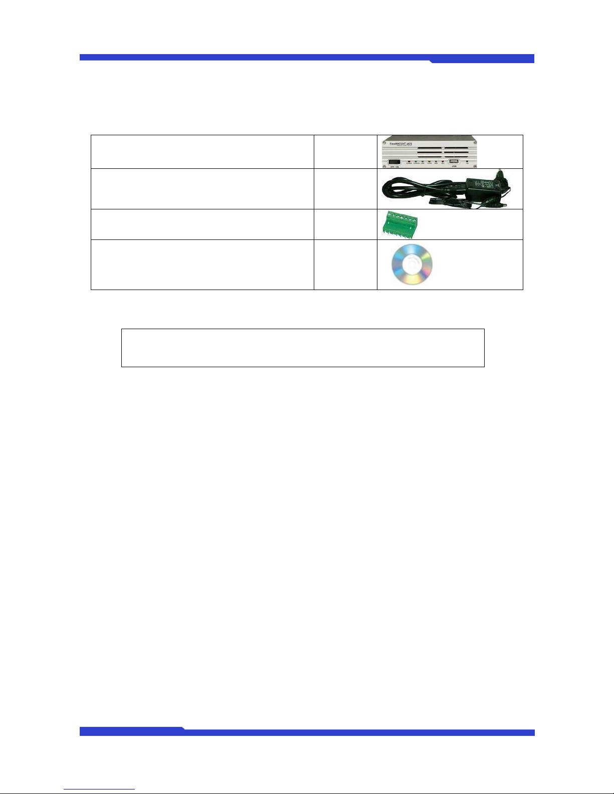
1.4. FW3470 Packing List
FW3470 Network Video Server 1 EA
Power Supply
(Power Cable & SMPS DC12V 3A Adapter) 1 EA
Terminal Block 7pin 2 EA
8pin 1 EA
Users Manual and CD 1 EA
Table 2 : FW3470 Packing List
Note: Please make sure all the listed items are included in the package. For any
missing items, please contact your local distributor.
FW3470 User’s Manual
M4059-00 9 Seyeon Tech Co., L d
2. Product Description
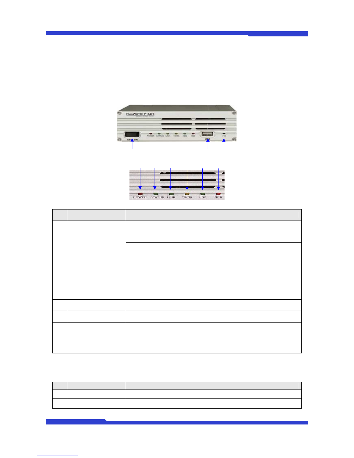
2.1. FW3470 Front View
Picture 2 : FW3470 Front View
Picture 3 : Enlarged Front LED
Name Description
A Power On/Off Switch
This switch is used to turn FW3470 On or Off.
Note: Never turn off during formatting the HDD because it may cause a
severe damage to it.
B POWER LED This red LED is lit during FW3470 is powered on.
C STATUS LED Shows the operating status of FW3470. It goes green when it enters into
normal operation after powered on and booting process.
D LAN LINK LED Indicates the connection status of LAN connector. It goes green when a
physical connection is properly made to the LAN port.
E LAN(Tx/Rx) LED Blinks green when there is any data activity on the LAN port.
F HDD LED Not supported for FW3470.
G RECORDING LED Not supported for FW3470.
H USB port USB port (reserved for future use)
I Factory Default Switch Restore the factory default setting for FW3470. Keep pressing this button for
5 seconds after a system boot up.
Table 3 : FW3470 Front Panel
Beep Sound Description
Name Description
1 Power ON One short beep if boot-up is started normally.
2 System Ready Two short beeps if boot-up is finished normally.
Table 4 : FW3470 Beep Sound
B
A
C
D
E
F
G
I
H

FW3470 User’s Manual
M4059-00 10 Seyeon Tech Co., L d
2.2. FW3470 Rear View
Picture 4 : FW3470 Rear View
A B C D E F G H I J K
이름 설명
A Video In 1 BNC connector for Camera 1
Video In 2 BNC connector for Camera 2
Video In 3 BNC connector for Camera 3
Video In 4 BNC connector for Camera 4
B Audio In 1 3.5mm Audio Jack for Audio-In 1
Audio In 2 3.5mm Audio Jack for Audio-In 2
Audio In 3 3.5mm Audio Jack for Audio-In 3
Audio In 4 3.5mm Audio Jack for Audio-In 4
C 12V output 12V power supply for external device (not over 0.5A)
D DI Sensor/Contact Input Port
E DO Beacon/Alarm Output Port
F AUX Auxiliary port for Modem or other devices (PTZ, UART-Out, Audio, UART-In)
G LAN RJ-45 Network Connector
H COM Control port for setup or other devices ( PTZ, UART-Out, Audio, UART-In)
I Power DC 12V 3A
J Audio Out Speaker jack to receive audio in 2-way audio communication.
K Video Quad Out Video output port for quad-view on the screen.
Table 5 : FW3470 Rear Panel

FW3470 User’s Manual
M4059-00 11 Seyeon Tech Co., L d
2.2.1. COM Port Description
The picture below shows how to wire the COM port connector pins when configuring the FW3470 with
console. Each signal should be wired to the correct pin as shown in the picture. It is a common practice to
use only RXD, TXD, and GND signals for RS-232 functionality. If FW3470 needs to be connected a computer
through RS-232, then RXD and TXD pin may need to be cross-wired.
Picture 5 : COM Port Description

FW3470 User’s Manual
M4059-00 12 Seyeon Tech Co., L d
3. FW3470 Installation and Basic Setup
3.1. Before Installation
Read carefully User's Manual.
Check User’s Network (IP Address, Network Mask and default gateway)
Secure IP address for FW3470.
3.2. Factory Default Settings
The following table shows the factory default condition. Please refer to this when you need to change
the values on admin menu.
Factory Default
Admin ID root
Admin password root
IP address 10.20.30.40
Network mask 255.255.255.0
Gateway 10.20.30.1
Table 5 : Factory Default
Note:
Factory default Admin ID and Password are all lower case letters. You can change the
password with Capital letters.
3.3. Installing FW3470
For installation of FW3470, please follow the steps below.
1.
Place the CCTV cameras in place and connect power supplies.
2.
Connect the video output ports of analog CCTV cameras to the video-in ports of FW3470.
3.
Connect the FW3470 to the Internet cable through the LAN port.
4.
Connect the power supply of FW3470.
After that, you need to follow the steps below.
Network Configuration: Refer to “IP Installer User’s Manual”
Camera Configuration: Refer to “FlexWATCH Admin Menu User’s Manual”
Service Configuration: Refer to “FlexWATCH Admin Menu User’s Manual”
Table of contents
Other Seyeon Network Hardware manuals


Popular Network Hardware manuals by other brands

ProfiTap
ProfiTap C1-1G-RG2 product manual

Crestron
Crestron DigitalMedia DM-RPP-K24 Guide

Patton electronics
Patton electronics RocketLink-G 3008/I quick start guide

ProfiTap
ProfiTap ProfiShark 10G user manual

8e6 Technologies
8e6 Technologies Enterprise Filter Authentication R3000 user guide

CNB
CNB KNU series user manual


