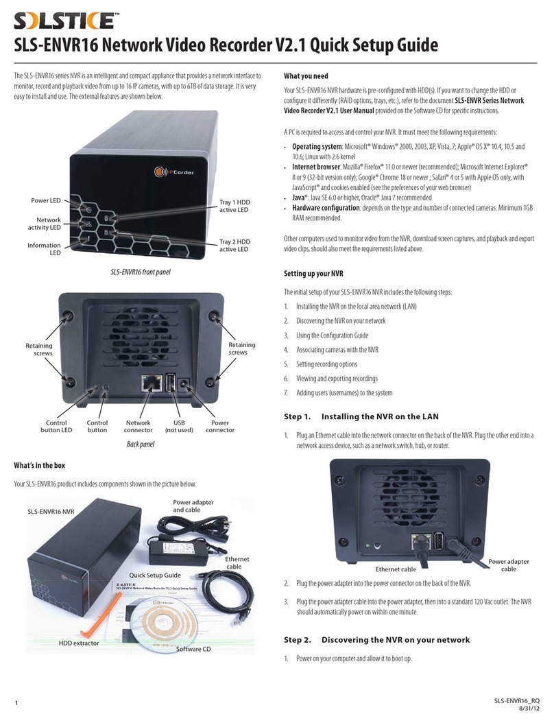
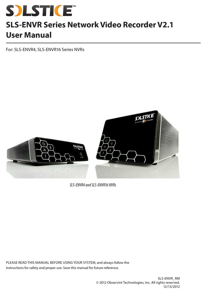
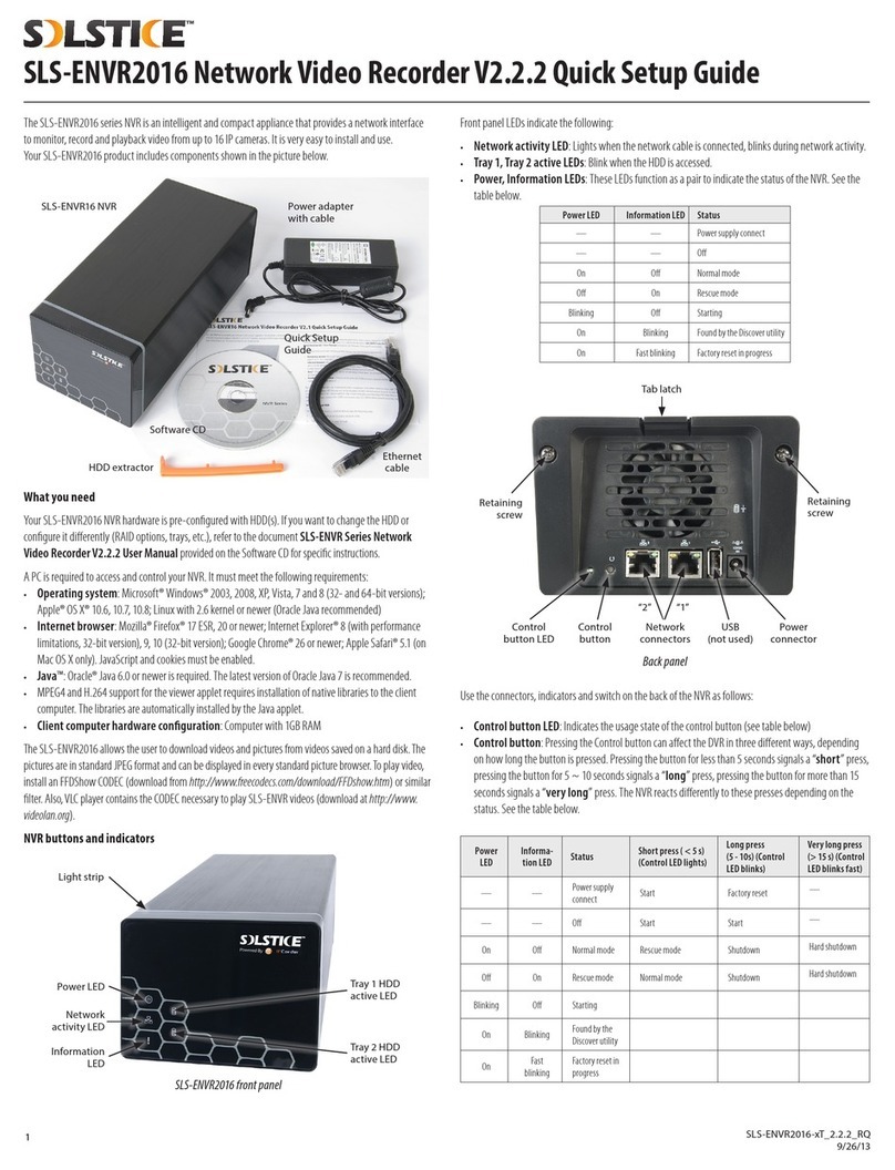
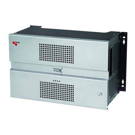
Solstice SLS-ENVR Series User manual

For: SLS-ENVR16 Series NVRs
SLS-ENVR16 Series NVR
PLEASE READ THIS MANUAL BEFORE USING YOUR SYSTEM, and always follow the
instructions for safety and proper use. Save this manual for future reference.
SLS-ENVR16-xT_RM
© 2012 Observint Technologies, Inc. All rights reserved.
10/19/2012
SLS-ENVR Series Network Video Recorder V2.1
User Manual
PRELIMINARY

ii
CAUTION
Operate this device only in environments where the temperature or humidity is within the recommended range. Operation
at extreme temperatures or in very high or low humidity levels may cause electric shock and shorten the life of the product.
CAUTION
Installation and servicing should be performed by qualied and experienced personnel only. DVR should always remain OFF
during any installation process.
CAUTION
Do not use this device if fumes, smoke or a strange odor is emitted, or if it seems to function incorrectly. Disconnect the
power source immediately, and consult your dealer.
LEGAL NOTICE
Observint Technologies (Observint) products are designed to meet safety and performance standards with the use
of specic Observint authorized accessories. Observint disclaims liability associated with the use of non-Observint
authorized accessories.
The recording, transmission, or broadcast of any person’s voice without their consent or a court order is strictly
prohibited by law.
Observint makes no representations concerning the legality of certain product applications such as the making,
transmission, or recording of video and/or audio signals of others without their knowledge and/or consent. We
encourage you to check and comply with all applicable local, state, and federal laws and regulations before
engaging in any form of surveillance or any transmission of radio frequencies.
SOLSTICE is a trademark of Observint Technologies.
Microsoft, Windows, Windows Media, and Internet Explorer are either registered trademarks or trademarks of Microsoft
Corporation in the United States and/or other countries. Android is a trademark of Google Inc. Use of this trademark
is subject to Google Permissions. Apple and OS X are registered trademarks of Apple Inc. Intel and Pentium are
trademarks of Intel Corporation in the U.S. and/or other countries.
Other trademarks and trade names may be used in this document to refer to either the entities claiming the marks
and names or their products. Observint disclaims any proprietary interest in trademarks and trade names other than
its own.
No part of this document may be reproduced or distributed in any form or by any means without the express written
permission of Observint.
© 2012 by Observint Technologies, Inc. All Rights Reserved.
11000 N. Mopac Expressway, Building 300, Austin, TX 78759
For Sales and Support, please contact your distributor.
PRELIMINARY

iii
SLS-ENVR Series NVR V2.1 User Manual
SAFETY INSTRUCTIONS
Safety Instructions
• To reduce risk of electric shock, do not disassemble this device.
• Use only the power supplies provided with the device.
• Defective parts must be replaced by original spare parts only.
• If you spill liquid on the NVR, unplug it from the AC outlet to prevent possible re or shock hazard, then consult authorized
service personnel for repair.
• When cleaning the device, turn it o rst. Use a clean soft cloth moistened with a little bit of water to clean it.
• If the device does not work properly, return it to the dealer where it was purchased. Do not dismantle it by yourself.
• Do not use the device close to heater, refrigerator or stove.
• Handle your NVR with care; it contains a hard disk drive.
—It is possible to damage hard drives if they are moved while their motors are still running. To allow the hard drive to spin
down and park its heads, wait at least 10 seconds after disconnecting power before moving the unit.
—To avoid shock and vibration damage to the internal hard drive, do not move the unit while it is plugged in.
—Protect hard disk drives from static electricity.
—Do not stack hard disk drives or keep them upright.
—Do not use an electric or magnetic screwdriver to x hard disk drives.
• Do not place the unit in an enclosed area where the air ow through the cooling vents is impeded.
• Protect the power cord from being stepped on or pinched particularly at plugs and the points where they exit from the
apparatus.
• Do not drop metallic parts through slots. This could permanently damage the device. Turn the power o immediately and
contact qualied service personnel for repair.
• Do not overload outlets and extension cords as this may result in a risk of re or electric shock.
Important notice
1. The manufacturer is not liable for potential damage caused by incorrect usage or placing the device in an unsuitable
environment.
2. The device is not designed for outdoor use.
3. Do not use the device in an environment with strong vibrations.
4. Unauthorized modication of this device can damage it or cause re.
5. Prevent contact with uids; do not expose the device to high temperatures.
6. If the device malfunctions, contact your distributor.
PRELIMINARY

iv
TABLE OF CONTENTS
Table of Contents
SECTION 1 Systems Overview ...................................................................1
1.1 System description ...................................................................1
1.2 System requirements .................................................................3
SECTION 2 Installation and Setup ...............................................................4
2.1 SLS-ENVR16 hardware features ........................................................4
2.1.1 Switches and indicators ..........................................................5
2.1.2 HDD installation .................................................................7
2.1.3 NVR installation .................................................................9
2.2 Discover utility .....................................................................10
2.3 Conguration Guide utility ...........................................................13
2.4 RAID Array Conguration utility .......................................................17
2.5 Adding cameras to the system ........................................................18
2.6 Camera viewing options .............................................................23
2.6.1 Control of View frames ..........................................................23
2.6.2 Create Views ...................................................................24
2.6.3 Moving panels and frames .......................................................26
2.7 PTZ camera control ..................................................................27
2.8 Conguring cameras for recording .....................................................28
2.9 Playback and export recordings .......................................................31
2.10 Adding users to the system ...........................................................34
2.11 Firmware Upgrade ..................................................................36
2.11.1 Registering your SLS-ENVR .......................................................37
2.11.2 Perform Online rmware upgrade .................................................37
2.11.3 Perform oine rmware upgrade .................................................38
SECTION 3 Settings Menu Reference ............................................................40
3.1 Devices menu ......................................................................41
3.1.1 Add devices ....................................................................41
3.1.2 Delete devices .................................................................41
3.1.3 Device Status list ...............................................................41
3.1.4 Network Grid ..................................................................42
3.1.5 Authentication Grid .............................................................42
3.1.6 Device trees ...................................................................42
3.2 Users menu ........................................................................44
PRELIMINARY

v
SLS-ENVR Series NVR V2.1 User Manual
TABLE OF CONTENTS
3.3 Schedules menu ....................................................................45
3.4 Action menu .......................................................................46
3.5 Conguration menu .................................................................47
3.5.1 Network menu .................................................................47
3.5.2 Email menu ....................................................................48
3.5.3 Date and Time menu ............................................................49
3.5.4 FTP menu .....................................................................49
3.5.5 Storage menu ..................................................................50
3.5.6 Congure Storage button ........................................................51
3.5.7 Remote Access menu ............................................................52
3.5.8 Conguration Wizard ...........................................................52
3.5.9 Customization menu ............................................................52
3.6 System menu. . . . . . . . . . . . . . . . . . . . . . . . . . . . . . . . . . . . . . . . . . . . . . . . . . . . . . . . . . . . . . . . . . . . . . .52
3.6.1 Shutdown / Restart menu .......................................................52
3.6.2 Firmware Upgrade menu ........................................................53
3.6.3 Factory Reset menu .............................................................55
3.6.4 System Log menu ..............................................................55
3.6.5 Backup / Restore menu ..........................................................56
3.7 Preferences menu ...................................................................58
3.7.1 User Preferences menu ..........................................................58
3.7.2 Change Password menu .........................................................58
SECTION 4 System / Remote Access .............................................................59
4.1 Router setup guidelines ..............................................................60
4.2 NVR setup guidelines ................................................................60
APPENDIX A Status Monitor Denitions ..........................................................63
APPENDIX B FAQ ..............................................................................64
APPENDIX C IPCorder Mobile (for Android) ........................................................65
PRELIMINARY

vi
NOTES
PRELIMINARY

1
SLS-ENVR Series NVR V2.1 User Manual
SECTION 1: SYSTEM OVERVIEW
SECTION 1
Systems Overview
Thank you for purchasing a SLS-ENVR Series Network Video Recorder! The SLS-ENVR is a standalone NVR for systems with IP
cameras, including the latest multi-megapixel resolution cameras in this industry. This NVR denes a new generation of network
recording solutions, characterized by easy usage, wide device support, compact dimensions, low power consumption, and reliable
operation.
You can watch and store video from your IP cameras, easily nd, play and export recorded videos. Storage of data from
temperature or humidity sensors is also available. Besides great exibility of the denition of recording modes, the NVR can react
on specic events such as recording video only when the door is locked, turning PTZ cameras, control external devices etc. The NVR
uses industrial standard SATA hard drives to record data.
1.1 System description
The SLS-ENVR NVR is the network based device that provides centralized administration of of digital security devices (cameras,
sensors) and their data. The user (administrator or security monitor user) communicates with NVR via a web browser interface
from their PC. The number of devices that can be connected to the NVR diers according to the specic SLS-ENVR model.
The NVR provides a centralized repository for collection of and access to data from the devices. The system administrator can dene
the conditions under which the video recording made and for how long. The records are stored in the central database, in which it
is possible to subsequently search for and browse them. The data from the sensors can be exported as tables in html format; videos
and pictures from the cameras can be stored in a le by a single click.
The system displays current data from the sensors in a uniform manner, independent of the given equipment. It is possible to
simultaneously display outputs from various devices while playing back recorded information. The user initially selects the devices
from which he/she want to see the outputs simultaneously (i.e. view), and can save the setup. Views can be stored and edited, so it
is not necessary to redene everything again.
Your NVR was designed with several advanced features, including:
Live View and Playback
• Simultaneous Live View and Playback display
• Drag and drop customizable viewing grid (live views, recordings, values)
• Full screen mode and support for multiple viewing screens
• Automatic or manual video stream selection
• Digital zoom feature with digital pan/tilt
• Display of numerical values from SLS-ENVR, cameras, sensors and other devices
• User buttons to trigger custom Actions
PRELIMINARY

2
SECTION 1: SYSTEM OVERVIEW
• MJPEG/MPEG-4/H.264 + PCM/AAC audio codecs supported
• PTZ control with preset lists and digital zoom
• Synchronized playback on selected channels
• Search for recordings by motion detection or other events with date-time interval
• Event/Value charts display during search
• Export to AVI, MKV, JPEG
• Export of selected time period of recorded video to a single le
• Export of stored numerical values from selected time period
• IPCorder Mobile app for Android (See “APPENDIX C IPCorder Mobile (for Android)” on page 65 )
Recording Modes
• Permanent or event based (motion detection, digital input trigger etc.)
• Timeline with event highlights
• Loop play, speed control, frame by frame playback
• Batch export of multiple channels
• Multiple independent recording schedules
Supported cameras, video servers and other devices
• ONVIF™ protocol support
• Supported brands: ACTi®, Arecont Vision, AXIS™, D-Link®, Hikvision®, IQinVision®, Linksys®, Lumenera®, Panasonic®, Sony®,
StarDot Technologies®, VIVOTEK®, Y-CAM
• KOUKAAM™ NETIO™ series
• External I/O and sensor (temperature, humidity etc.) devices from company HW Group – Poseidon and Damocles products,
etc. For a complete list please see: http://www.ipcorder.com/en/support/supported-devices/
Special Features
• Easy creation of custom actions triggered by events or user buttons
• Schedules for recording and actions limitation
• Hard disc and system health check with reports
• Automatic recovery after power outage
• Setup wizard
• E-mail support – SMTP / TLS
• Custom sender address
Remote Access
• Router control - Automatic (UPnP port forwarding) or static forwarding setup
PRELIMINARY

3
SLS-ENVR Series NVR V2.1 User Manual
SECTION 1: SYSTEM OVERVIEW
Networking
• 10/100/1000 Mbps Ethernet, RJ-45
• Supported protocols: IPv4, TCP/IP, UDP, HTTP, UPnP, RTSP / RTP / RTCP, SMTP, FTP, DHCP, NTP, DNS, ONVIF, HTTP multipart
1.2 System requirements
A PC is required to access and control your NVR. It must meet the following requirements:
• Operating system: Microsoft® Windows® 2000, 2003, XP, Vista, 7; Apple® OS X® 10.4, 10.5 and 10.6; Linux with 2.6 kernel
• Internet browser: Mozilla® Firefox® 11.0 or newer (recommended); Microsoft Internet Explorer® 8 or 9 (32-bit version only);
Google® Chrome 18 or newer ; Safari® 4 or 5 with Apple OS only, with JavaScript® and cookies enabled (see the preferences of
your web browser)
• Java®: Java SE 6.0 or higher, Oracle® Java 7 recommended
• Hardware conguration: depends on the type and number of connected cameras. Minimum 1GB RAM recommended.
Other computers used to monitor video form the NVR, download screen captures, and playback and export video clips, should also
meet the requirements listed above.
Additionally, if recording video from several cameras, it is highly recommended to have the NVR connected to a gigabit LAN.
PRELIMINARY

4
SECTION 2: INSTALLATION AND SETUP
SECTION 2
Installation and Setup
2.1 SLS-ENVR16 hardware features
Special features:
• Manage/record/view up to 16 IP cameras/video servers simultaneously
• Compact size and quiet operation
• Up to 6TB data storage with 2 HDDs
• Power consumption - 12 Vdc, up to 48 w (typical with 2 HDDs)
• Automatic recovery after power outage
• Package contains:
—NVR - SLS-ENVR16 with pre-installed HDD(s)
—Power adaptor 100 – 240 Vac, 50/60 Hz to 12 Vdc and power cable
—Network cable
—HDD ejector rails (2)
—Quick Installation Guide, License agreement
—CD with Discover Utility and documentation
Software CD
SLS-ENVR16 NVR
Ethernet
cable
Quick Setup
Guide
Power adapter
and cable
HDD extractor
PRELIMINARY

5
SLS-ENVR Series NVR V2.1 User Manual
SECTION 2: INSTALLATION AND SETUP
2.1.1 Switches and indicators
Power LED Tray 2 HDD
active LED
Tray 1 HDD
active LED
Network
activity LED
Information
LED
SLS-ENVR16 front panel
Front panel LEDs indicate the following:
• Network activity LED: Lights when the network cable is connected, blinks during network activity.
• Tray 1, Tray 2 active LEDs: Blink when the HDD is accessed.
• Power, Information LEDs: These LEDs function as a pair to indicate the status of the NVR . See the table below.
Power LED Information LED Status
— — Power supply connect
— — O
On O Normal mode
O On Rescue mode
Blinking O Starting
On Blinking Found by the Discover utility
On Fast blinking Factory reset in progress
PRELIMINARY

6
SECTION 2: INSTALLATION AND SETUP
Retaining
screws
Retaining
screws
Control
button
Control
button LED
LAN
connector
USB
connector
Power
connector
Back panel
Use the connectors, indicators and switch on the back of the NVR as follows:
• Control button LED: Indicates the usage state of the control button (see table below)
• Control button: Pressing the Control button can aect the DVR in three dierent ways, depending on how long the button
is pressed. Pressing the button for less than 5 seconds signals a “short” press, pressing the button for 5 ~ 10 seconds signals
a “long” press, pressing the button for more than 15 seconds signals a “very long” press. The NVR reacts dierently to these
presses depending on the status. See the table below.
Power LED Information
LED Status Short press ( < 5 s)
(Control LED lights)
Long press (5 - 10 s)
(Control LED blinks)
Very long press ( > 15 s)
(Control LED blinks fast)
— — Power supply connect Start Factory reset —
— — O Start Start —
On O Normal mode Rescue mode Shutdown Hard shutdown
O On Rescue mode Normal mode Shutdown Hard shutdown
Blinking O Starting
On Blinking Found by the Discover
utility
On Fast blinking Factory reset in progress
• LAN connector: Used to connect an Ethernet cable to the NVR.
• USB connector: For future use.
• Power connector: Used to connect the power adapter provided (12 Vdc) to the NVR.
PRELIMINARY

7
SLS-ENVR Series NVR V2.1 User Manual
SECTION 2: INSTALLATION AND SETUP
2.1.2 HDD installation
The SLS-ENVR16 NVR will accommodate either one or two SATA I or SATA II HDDs, up to 3TB each. Although most SATA HDDs will
function in the NVR, we recommend that a security grade HDD manufactured by Seagate, Western Digital or Hitachi be used. An
HDD must be installed before using the NVR.
If only one HDD is installed, it should be installed in the upper tray (Tray 1) and can be congured for RAID 0 or Linear recording.
When two HDDs are installed, they can be congured for RAID 0 or 1, or Linear recording. However, if they are congured for
RAID1, the two HDDs should have the same storage capacity to fully utilize the drives.
After installing the HDD, powering on the NVR (see “2.2.3 NVR installation” on page 12), and logging into the device (“2.3 Discover
utility” on page 13), you will be prompted to execute an HDD RAID Array Conguration utility to set the RAID conguration of your
HDDs (see “2.4 RAID Array Conguration utility” on page 17).
CAUTION
Always follow recommended electrostatic discharge (ESD) guidelines while performing this procedure. Install the HDD in a
static-free environment, wearing a certied ESD wrist strap. If a static free environment and ESD wrist strap is not available,
touch the bare metal of the NVR chassis frequently when installing the drive to dissipate the static charge naturally generated
on your skin and clothing.
1. Un-package an HDD, then install the ejector as shown below. To attach the ejector to the HDD, align the pegs on the side of the
bar with the screw holes on the side of the HDD, then press them in until the bar is at along the side of the HDD.
Ejector
Ejector attached
PRELIMINARY

8
SECTION 2: INSTALLATION AND SETUP
2. If the NVR is powered on, power it o (see instructions “3.6.1 Shutdown / Restart menu” on page 52), then disconnect the power
adapter.
3. Remove the four retaining screws on the back of the NVR, then carefully set the NVR back cover to the side. Note that the back
cover and the NVR are connected by wiring.
4. Slide the HDD(s), connector end rst, into the trays inside the NVR enclosure.
Back cover
Tray 1
(upper)
Tray 2
(lower)
5. Apply even pressure across the back of the HDD to seat it onto the connectors inside the NVR. Do not push the HDD in using
the ejector.
HDDs installed
6. Reinstall the NVR back cover using the four retaining screws removed earlier.
PRELIMINARY

9
SLS-ENVR Series NVR V2.1 User Manual
SECTION 2: INSTALLATION AND SETUP
To remove an HDD:
CAUTION
Always follow recommended electrostatic discharge (ESD) guidelines while performing this procedure. Install the HDD in a
static-free environment, wearing a certied ESD wrist strap. If a static free environment and ESD wrist strap is not available,
touch the bare metal of the NVR chassis frequently when installing the drive to dissipate the static charge naturally generated
on your skin and clothing.
1. If the NVR is powered on, power it o (see instructions in “3.6.1 Shutdown / Restart menu” on page 52), then disconnect the
power adapter.
2. Remove the four retaining screws on the back of the NVR, then carefully set the NVR back cover to the side. Note that the back
cover and the NVR are connected by wiring.
3. Gently pull back on tab of the ejector rail to unseat the HDD from the connectors inside the NVR.
4. Slide the HDD out and set it aside. NOTE: If only one HDD is installed in the NVR, it should be in Tray 1 (upper tray).
5. If another HDD will be installed in the NVR, follow the procedure above.
6. Reinstall the NVR back cover using the four retaining screws removed earlier.
2.1.3 NVR installation
Step 1. Installing the NVR on the LAN
1. Plug an Ethernet cable into the LAN connector on the back of the NVR. Plug the other end into a network access device, such as
a network switch, hub, or router.
Ethernet cable
Power adapter
cable
2. Plug the power adapter into the power connector on the back of the NVR.
PRELIMINARY

10
SECTION 2: INSTALLATION AND SETUP
3. Plug the power adapter cable into the power adapter, then into a standard 120 Vac outlet. The NVR should automatically power
on within one minute.
2.2 Discover utility
Discover is a utility used to search for and localize an SLS-ENVR series NVR on the network. If you do not know the IP address of the
device, it is possible to nd it using Discover. This utility is provided on the enclosed CD, or online at http://www.ipcorder.com.
Unless the network conguration settings of your NVR were preset, the NVR is congured to use DHCP to acquire settings from a
local DHCP server. If the server is not available, the NVR defaults to a static network conguration with the IP address 192.168.1.78.
The network conguration parameters can be set using the Discover utility, the Conguration Guide utility (see “2.4 Conguration
Guide utility” on page 15), or within the SLS-ENVR web interface.
1. Power on your computer and allow it to boot up.
2. Insert the software CD into the optical drive and allow it to initialize (autorun). The screen shown below should open.
3. If Java is not loaded on your computer, click the Download Java button on the IPCorder window, then follow the on-screen
instructions to install it.
4. On the IPCorder window, click the Start Discover button.
5. In the Discover window (see below) open the Use network interface drop-down list, then select the network where your
NVR was installed.
PRELIMINARY

11
SLS-ENVR Series NVR V2.1 User Manual
SECTION 2: INSTALLATION AND SETUP
Open
network
list
6. In the IPCorder discover window, click the Discover button in the lower-right corner and wait until your NVR is found. If the
NVR was not found during the scan, click the Discover button again. In the screen above, the entry found for an NVR shows an
IP address of 192.168.5.19, the MAC address, and the rmware level. If you have multiple SLS-ENVRs on your network, verify
that the MAC shown matches the address on the label on the underside of your NVR.
NOTE The MAC address of the SLS-ENVR16 is shown on the product label on the underside of the unit.
7. You can change the network settings of the NVR through the SLS-ENVR web interface, with the Conguration Guide (see “2.3
Conguration Guide utility” on page 13), or with the Discover utility:
a. Click the entry line of the NVR once to select (highlight) it.
b. (Optional) Click the Locate button to identify the physical NVR. After clicking Locate, some LEDs on the front of the NVR
will ash. Verify that the NVR with the ashing LEDs is the unit you want to congure.
c. Click the Device setup button to open the Device pop-up window.
d. In the Device window, edit the network settings if necessary, then click the Change Settings button.
PRELIMINARY

12
SECTION 2: INSTALLATION AND SETUP
8. Double-click the line for your NVR in the Discover window. Depending on the state of the NVR, one of the following screens
will result:
a. If the NVR is new (started for the rst time) or just started after a factory reset procedure, the Conguration Guide utility
will open. See “2.4 Conguration utility” on page 15 to continue.
b. If the Conguration utility was used and the NVR was not previously reset to the factory default conguration, an NVR
web interface login window will open. Login to your NVR. The default values for Username and Password are admin
and admin.
After logging into your NVR, one of three screens will open, depending on the status of your NVR. Continue with the appropriate
procedure:
—If the NVR is started for the rst time after receiving if from your distributor, or a factory reset occurred previously, the
Conguration utility will open. Continue with “2.3 Conguration Guide utility” on page 13.
Or
—If the NVR is started for the rst time after a new (un-congured) HDD was installed, the RAID Array Conguration utility
will open. See “2.4 RAID Array Conguration utility” on page 17.
Or
—If the NVR is started after it was pre-congured, and the two conditions above don’t apply, the SLS-ENVR web interface
Video window will open.
PRELIMINARY

13
SLS-ENVR Series NVR V2.1 User Manual
SECTION 2: INSTALLATION AND SETUP
2.3 Conguration Guide utility
The Conguration Guide utility is a tool for setting up the basic conguration of your NVR. It includes selecting the screen
language, changing the default administrator password, setting the time format and NVR clock synchronization, network settings,
etc. The Conguration Guide utility opens during the initial setup of the NVR, after a factory reset of the NVR, and can be initiated
through the NVR web browser interface.
1. When the Conguration Guide utility opens, a login window appears. Enter your administrator Username and Password, then
click Log In. The default administrator Username and Password is admin and admin.
2. In the Conguration Guide - Welcome window, click the button next to “English” open the drop-down list. Select your
preferred language, then click Apply and Continue.
3. In the Conguration Guide - Change default administrator password window, enter your new password in both elds, then
click Apply and Continue. It is strongly recommended that you change the password to one with high security strength.
PRELIMINARY

14
SECTION 2: INSTALLATION AND SETUP
4. In the Conguration Guide - User preferences window, select the options appropriate for installation site, then click Apply
and Continue.
5. In the Conguration Guide - Date and Time window, select the options appropriate for location, then click Apply and
Continue. Note that an option is provided to synchronize the NVR with your computer.
Time Zone
First specify the local time zone in which the SLS-ENVR is being used by selection of area and city. This may dier from the time of
the computer from which we are connecting to the SLS-ENVR.
PRELIMINARY
Table of contents
Other Solstice Network Hardware manuals
