Connecting the Vi eo Outputs
from the Power Supply Passive
Receiver Hub to the Control Room
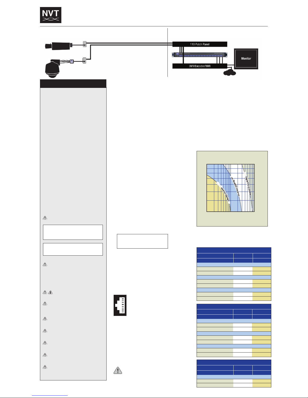
Connect the equipment video outputs on the rear of the Power
Supply Passive Receiver ub to the DVR, encoder, or multiplexer.
The NV-4PS13-PVD supports four channels.
The NV-8PS13-PVD supports eight channels.
The NV-16PS13-PVD supports sixteen channels.
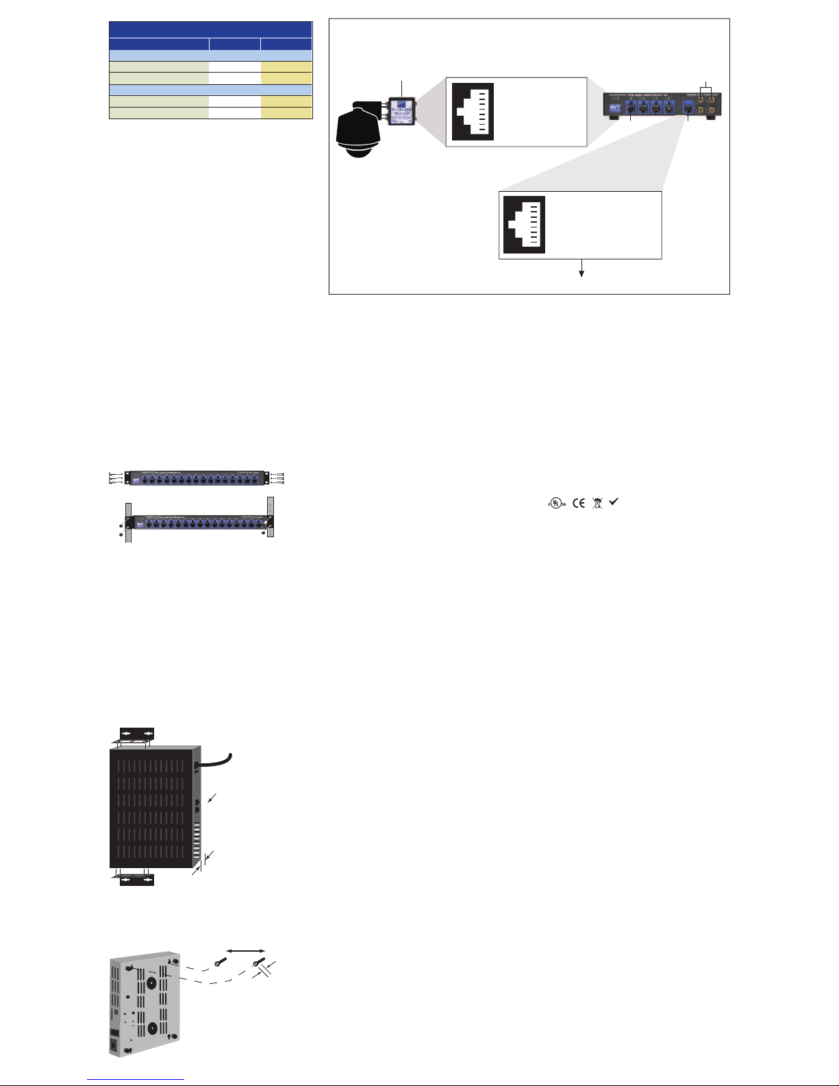
Data Connections
The data path for each camera arrives on the front RJ45 jack of the
Power Supply Cable Integrator. Each Data jack supports the pass-
through of four camera data signals. Use a 4-pair Cat5 cable to
bring these data signals back to the Control Room. For small
installations, these wire pairs may be connected directly to the RS-
422/485 telemetry control output on your controller. In most cases
a “Code Distribution Unit” (available from the camera manufacturer)
is inserted between the telemetry output and the wire-pairs. This
allows one telemetry output to drive many cameras without having
to drive too many loads. It also prevents a fault at one camera from
taking down the entire system.
NV-8PS13-PVD, NV-16PS13-PVD
Rack / Table Mounting
Ambient temperature must be below 122°F (50°C). Airflow must be
at least 4ft3/min of un-restricted airflow. Many DVRs produce
enough heat to exceed this temperature without external airflow.
For rack mounting, (8 and 16 Channel installation described below.
4-Channel NV-4PSRMBK rack mounting brackets purchased
separately). Attach supplied mounting brackets to the hub chassis
using the supplied screws. Note that the brackets allow installation
with the front or rear facing out.
Because the NV-16PS13-PVD weighs 25 lbs. (11,3kg), some
thinner-gauge rack systems may require additional rear support.
NVT provides a rear-rail mounting accessory kit (see Accessories)
for this purpose.
Table Tops: (4 Channel feet attached) for 8 & 16 Channels use
enclosed self adhesive rubber feet and attach to the bottom
corners of the hub.
NV-8PS13-PVD, NV-16PS13-PVD
Wall Mounting
Attach the optional mounting “L” brackets to two sides of the unit,
using the enclosed screws. The brackets may be installed facing
outward or inward. Inward facing brackets allow the unit to be
mounted on 16” centers, useful in US wall stud applications. For
easy connector and LED access, it is recommended that the front of
the unit faces left.
NV-4PS13-PVD Wall Mounting
For wall mounting, hang unit onto (2) Pan head screws mounted to
plywood backboard. Screw heads should be secured approximately
½” (1,2cm) off board surface and spaced 4.5” (11,43cm) apart.
Technical Specifications
Video, Passive Receiver
Frequency DC to 10 M z
Attenuation 0.5 dB typ
Common Mode/Differential Mode Rejection
15 K z to 5 M z 60dB typ
Power Output
3 Position 24VAC, OFF or 28VAC
Voltage witch Per-channel switch selectable
Current 1 Amp per channel
Protection
Automatic resetting termistor
Connectors and Impedance
RJ45 UTP input 100 ± 20 ohms
BNC output 75 ohms
LEDs
Power Blue
Channel Status see page 1
Environmental
Temperature 32 to 122°F (0 to 50°C)
Minimum airflow 4ft3/min (0,13mm)
umidity 0 to 95% non-condensing
Transient immunity per ANSI / IEEE687 C62.41
Power Input
IEC380 Inlet
Power Cord
IEC380 AC line power receptacle for use with removable cords.
Use only the power cord provided with the unit or equivalent
UL approved type SJT or SVT, 18AWG, 125/250V, 5A 60 deg.C,
Max. 4,5m long; One end with NEMA 5-15P. Other end with
appliance coupler.
NV-4P 13-PVD
Voltage 115/230 VAC
Frequency 50/60 z
Wattage 125 W
eat 50 BTU/ r (power supply only)
420 BTU/ r
(power supply with camera)
NV-8P 13-PVD
Voltage 115/230 VAC
Frequency 50/60 z
Wattage 250 W
eat 100 BTU/ r (power supply only)
900 BTU/ r
(power supply with camera)
NV-16P 13-PVD
Voltage 115/230 VAC
Frequency 50/60 z
Wattage 500 W
eat 125 BTU/ r (power supply only)
1,200 BTU/ r
(power supply with camera)
Fuse
NV-4PS13-PVD 2.5 Amp
NV-8PS13-PVD 2.5 Amp
NV-16PS13-PVD 5.0 Amp
A spare fuse is located inside the fuse holder.
Mechanical (Excluding brackets and connectors)
Dimensions
NV-4P 13-PVD
W9.25” (23,5cm) H1.7” (4,4cm) D7.3” (18,5cm)
NV-8P 13-PVD
W17” (43,2cm) H1.7” (4,4cm) D8.13” (20,7cm)
NV-16P 13-PVD
W17” (43,2cm) H1.7” (4,4cm) D12” (30,48cm)
Weight
NV-4P 13-PVD
Product Weight 7.0lb (3,14kg)
Packaged Weight 8.42lb (3,81kg)
NV-8P 13-PVD
Product Weight 14lb (6,35kg)
Packaged Weight 16.8lb (7,6kg)
NV-16P 13-PVD
Product Weight 25lb (11,3kg)
Packaged Weight 30.4lb (13,78kg)
Accessories
NV-4P 13-PVD
-Rubber feet for desk applications (attached)
- ole cutouts in bottom for wall mount
-Power cable IEC power cord 7ft (21,5cm)
-BNC patch cables: 2ft long purchased separately
-NV-4PSRMBK (rack mount kit) purchased separately
NV-8P 13-PVD and NV-16P 13-PVD
-Mounting: Rackmount “L” brackets for front or rear
installations; rubber feet for desk applications
-Rack screws: 4 12-24 x 3/4” Phillips Pan ead
-BNC patch cables: 2ft long 1 per channel
-Power cable IEC power cord 7ft (21,5cm)
-Optional Mounting Support Bracket Kits
Model NV-RMBK (rear mount kit) purchased separately
Model NV-WMBK (wallmount kit) purchased separately
Agency
These NVT products are listed and/or conform
to the following certifications and directives:
UL Listed to UL2044 or UL/IEC 60065.
cUL Listed to CAN/CSA22.2 No. 1 for Canada.
CE Mark under EMC and low voltage Directives for the
European Union.
Complies with FCC part 15B limits
Troubleshooting
If you are experiencing problems, attempt to simplify your setup.
Test each cable segment separately. For example, test the camera
and monitor together without the other equipment. Then add in the
NVT transceivers, back-to-back. Test each segment of a long cable-
run independently. Attempt to isolate the problem.
Customer Support
NVT customer support is available for consultation from 8:00 AM to
5:30 PM PST Monday through Friday. In addition, emergency after-
hours callback support is available.
US Office: (+1) (650) 462-8100
US Fax: (+1) (650) 326-1940
UK Office: (+44) (0)20 8977 6614
UK Fax: (+44) (0)20 8973 1855
Email USA: www.nvt.com/email
Email UK: www.nvt.com/email
Web home page: www.nvt.com
Returns
Please call before returning units to NVT. Returned materials must
have a “Returned Materials Autorization” (RMA) number from NVT
marked on the outside of the shipping carton.
Limite Lifetime Warranty
NVT warrants that the product conforms to NVT’s applicable
published specifications and is free of defects for the life of the
product. There shall be no other warranties, express, statuatory, or
otherwise, including any implied warranty of merchantability, of
fitness, or any other obligation on the part of NVT with respect to any
of the products.
In the event that any of the products is damaged, altered, or
modified without the express written consent of NVT, any warranty
for those products will cease and NVT will have no further liability as
it pertains to those products.
NVT assumes no responsibility for damages or penalties incurred
resulting from the use of this product in a manner or location other
than for which it is intended.
NVT’s liability under any warranties shall be discharged by
replacing or repairing any part or parts which do not conform to the
applicable warranty under normal and proper use. NVT’s liability
with respect to any product shall not exceed a refund of the price
received by NVT for that product, and in no event shall NVT have any
liability for any incidental, consequential, special, or indirect
damages.
Some states do not allow the exclusion or limitation of special,
incidental, or consequential damages, so the above limitations or
exclusions may not apply to you. This warranty gives you specific
legal rights, and you may also have other rights which vary from
state to state.
Specifications subject to change without notice