Shadow-Caster SCM-MFD-LC-KIT User manual
WWW.SHADOW-CASTER.COM
INSTALLATION & OPERATION MANUAL
SCM-MFD-LC-KIT
MFD LIGHTING
CONTROLLER KIT

SCM-MFD-LC-KIT
OPERATION MANUAL
Shadow-Caster®LED Lighting | 2060 Calumet Street. | Clearwater, FL 33765
p: 1+ 727.474.2877 e: info@shadow-caster.com w: shadow-caster.com
2
TABLE OF CONTENTS
SCM-MFD-LC-KIT BOX CONTENTS ................................................................................................................................
COMPATIBILITY & OPTIONS ..........................................................................................................................................
SCM-MFD-LC-KIT OVERVIEW ........................................................................................................................................
SCM-MFD-LC-KIT TYPICAL WIRING DIAGRAM .............................................................................................................
INITIAL ONBOARDING STEPS.........................................................................................................................................
SHADOW-CASTER® LIGHTING HOME SCREEN.............................................................................................................
CONFIGURING ZONES....................................................................................................................................................
USINGSCENES................................................................................................................................................................
CONFIGURING PROGRAMS...........................................................................................................................................
MUSIC SYNC CONFIGURATION.....................................................................................................................................
CONNECTING THE SCM-MFD-BRIDGE & INITIAL SYNCING..........................................................................................
INSTALLATION ...............................................................................................................................................................
ADDING ADDITIONAL REMOTES AND MULTI-FUNCTION DISPLAYS ..........................................................................
SHADOW-NET®DEVICES ...............................................................................................................................................
OPTIONAL PARTS ...........................................................................................................................................................
BEST PRACTICES FOR MITIGATING NOISE ISSUES ....................................................................................................
CONNECTING STEREO INPUT FOR STEREO MUSIC SYNC INPUT ..............................................................................
TROUBLESHOOTING ......................................................................................................................................................
3
3
4
4
5
7
7
8
8
9
9
10
11
11
11
11
11
12

SCM-MFD-LC-KIT
OPERATION MANUAL
SCM-MFD-LC-KIT BOX CONTENTS
•SCM-MZ-LC Multi-Zone Lighting Controller
•SCM-MFD-BRIDGE Multi-Function Display Bridge
•8 x SS316 Pan Head 8 x ¾" Mounting Screws
•Installation & Operation Manual
•Warranty and Registration Information
PRODUCT SERIAL NUMBER
You can add your product serial number here for
warranty and product registration purposes.
The serial number is located on a white label inside the
housing of the SCM-MZ-LC.
My Serial Number:
COMPATIBILITY & OPTIONS
Manufacturer Optional IP67
Shadow-Caster®Cable
Required Cable from
Manufacturer
SCM-MFD-Cable Garmin
PN: 010-10550-00 (6ft Cable)
PN: 010-10551-00 (20ft Cable)
PN: 010-10552-00 (40ft Cable)
PN: 010-10580-10 Isolator
SCM-MFD-Cable Navico
SCM-MFD-Cable Navico
-
SCM-MFD-Cable Navico
PN: 000-14552-001 (1.5m Cable)
SCM-MFD-Cable Navico PN: 000-14552-001 (1.5m Cable)
SCM-MFD-Cable Navico PN: 000-14552-001 (1.5m Cable)
- PN: A80247 (2m Cable)
- -
3
Designed & Manufactured
in Clearwater, FL
© 2021 Shadow-Caster®LED Lighting, All Rights Reserved
SCM-MFD-LC-KIT
OPERATION MANUAL
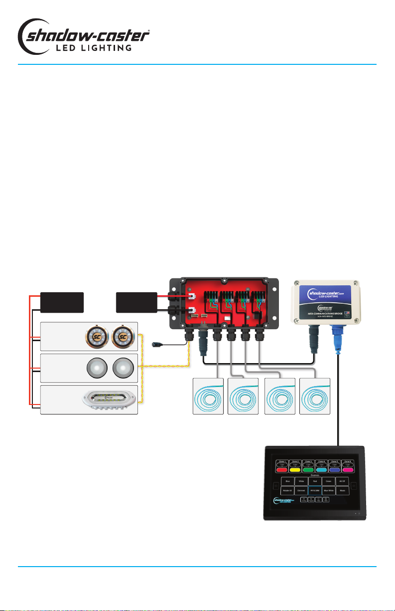
SCM-MFD-BRIDGESCM-MZ-LC
SCR-24-CC
Underwater
Lights
Defaults to Zone 1 3.5mm Female
Audio Jack
4 x Channels of RGB Lighting
(supports up to 15A per channel)
Shadow-NET
12V DC
Power Source
10-30V DC
Power Source
RGB Zone 1 RGB Zone 2 RGB Zone 3 RGB Zone 4
SCM-SL-CC
Spreader Lights
Defaults to Zone 3
SCM-DLX-CC or
SCM-DL-CC Down
Lights
Defaults to Zone 2
SCM-MFD-LC-KIT TYPICAL WIRING DIAGRAM
MFD
Shadow-Caster®LED Lighting | 2060 Calumet Street. | Clearwater, FL 33765
p: 1+ 727.474.2877 e: info@shadow-caster.com w: shadow-caster.com
4
SCM-MFD-LC-KIT OVERVIEW
The Shadow-Caster®MFD Lighting Control Kit (SCM-
MFD-LC-KIT) includes the Multi-Zone Lighting Controller
(SCM-MZ-LC) and the MFD Bridge (SCM-MFD-BRIDGE).
The SCM-MZ-LC Lighting Controller supplies fused
power connection for up to 4 separate zones of user
selectable RGB or RGBW lighting. It can receive an
analog music input, and also broadcasts multiple
channels of digital commands to other devices on the
Shadow-NET®Bus (orange and yellow wires).
The SCM-MFD-BRIDGE provides a control interface to
the Multi-Zone Lighting Controller through an Ethernet
connected MFD (Multi-Function Display) or other
connected device.
The control interface steps you through selecting and
naming a desired number of control zones. The setup
process will also identify all additional Shadow-NET®
connected devices and assign them to the desired
lighting zone. The zones can then be assigned to a
desired color and brightness or even congured for
an active lighting program. The program is saved as a
unique 'lighting scene' for easy recall.
At initial power up the Shadow-NET®bus will broadcast
messages to tell connected devices to turn off. This
allows these devices to be used without a dedicated
switch. When the SCM-MZ-LC controller receives a
command to turn on, it will send a corresponding
command to devices connected on the Shadow-NET®
bus.
Note: Lighting connected to outputs 1-4 of the SCM-MZ-LC will always
correspond to zones 1-4 in the lighting application. Shadow-Net®
connected lights can be assigned to any zone 1-6.

2. Upon opening the lighting app you should see the
welcome screen.
Press the NEXT button to initiate the system and
proceed through the onboarding process detailed in the
following steps.
USING THE INTERFACE
INITIAL ONBOARDING STEPS
1. Select the Shadow-Caster Lighting app icon from
your MFD home screen.
SCM-MFD-LC-KIT
OPERATION MANUAL
3. Select the brand/manufacturer of your chosen MFD
as shown here.
Once selected press NEXT button to conrm.
5
Designed & Manufactured
in Clearwater, FL
© 2021 Shadow-Caster®LED Lighting, All Rights Reserved
4. Select the number of lighting zones required for your
system.
Once selected press NEXT button to conrm.
Note: RGB zones 1-4 are statically assigned to their
corresponding zone but Shadow-NET®lights can be
assigned to any zone number.
5. Step through the individual lighting zones and give a
unique name. This can also be done later through the
Cong Menu.
Once selected press NEXT button to conrm.

SCM-MFD-LC-KIT
OPERATION MANUAL
Shadow-Caster®LED Lighting | 2060 Calumet Street. | Clearwater, FL 33765
p: 1+ 727.474.2877 e: info@shadow-caster.com w: shadow-caster.com
6
8. Once all the devices are found by the system, They
can be identied by clicking "Identify". All connected
lights will turn off, and the light being identied will
ash white slowly.
Once identied, set the lights to their desired zones.
Once selected press NEXT button to conrm.
6. Please make sure that all of the lighting devices
on the network are powered and connected. The
system will go through and identify everything that is
connected.
Once selected press NEXT button to conrm.
7. Select the required Operation Mode:
Full Mode (Recommended)
Full Mode allows individual control of all devices
connected to the Shadow-NET bus. This is the
recommended setting.
Global Mode
Global Mode only allows control of everything on the
bus as one channel. This is only required for working
with certain older technology underwater lights (pre
2018).
Once selected press NEXT button to conrm.
SCM-MFD-LC-KIT
OPERATION MANUAL
7
Designed & Manufactured
in Clearwater, FL
© 2021 Shadow-Caster®LED Lighting, All Rights Reserved
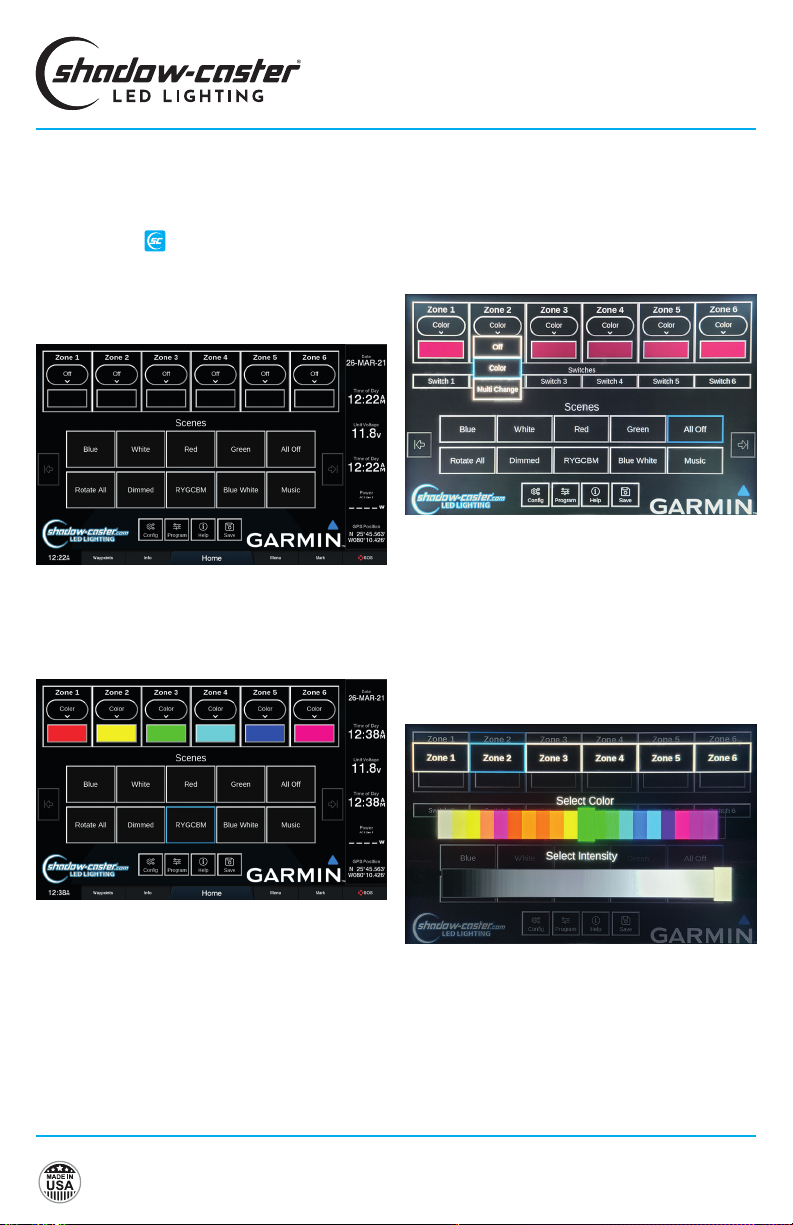
SHADOW-CASTER®LIGHTING
HOME SCREEN
This is the default screen by clicking on the Shadow-
Caster®app icon after the onboarding process has
been completed.
Scenes can now be easily recalled by pressing a scene
button.
There are several preset scenes already congured.
An example of the Home Screen after the 'RYGCBM'
scene is recalled is shown below.
Note: 'RYGCBM' is short for Red/Yellow/Green/Cyan/
Blue/Magenta.
CONFIGURING ZONES
In the zone control box, there are two buttons.
Pressing the top button reveals a drop down selection
with three options: turn the zone off; select color
and brightness control; or select the currently active
program.
The lower button indicates the current color and
brightness or the current program. To change the color,
press the current color button and the color scroll bar
will pop up.
Slide the color bar to select any color, or select the
intensity slider to change the brightness.
Note: Multiple zones can be selected at the same time
to allow multiple lighting zones to be controlled and
and changed together.

SCM-MFD-LC-KIT
OPERATION MANUAL
Shadow-Caster®LED Lighting | 2060 Calumet Street. | Clearwater, FL 33765
p: 1+ 727.474.2877 e: info@shadow-caster.com w: shadow-caster.com
8
CONFIGURING PROGRAMS
These are accessible by clicking on the PROGRAM
button .
MULTI-COLOR CHANGE PROGRAM
CONFIGURATION
Select Color Sequence pattern.
Select Intensity level.
Select the Speed of rotation.
STROBE PROGRAM CONFIGURATION
Select the desired color.
Then select Intensity (brightness) and Speed (rate of
strobe).
Program
DELETING A SCENE
Press and hold a scene button to delete it.
Note: Long press functions are not supported in all
Multi-Function Displays (MFDs).
UPDATING SCENES
Simply save over a scene name to update it.
SAVING A SCENE
Once all lighting zones are congured as desired, press
SAVE and a window will pop up with a text box.
USING SCENES
A 'Scene' is a way to have all of the zones in your
conguration set to a predetermined color, intensity or
lighting program.
New scenes can be saved and existing scenes can be
customized or removed to t your preferences.
SCENE OPTIONS CONFIGURATION
Assign a Powerup Scene for the lighting as soon at it
receives power.
Assign a Startup Scene for the lights to go to as soon
as the application opens up in the browser.

MUSIC SYNC CONFIGURATION
Select Type of Sync:
Single
Lights illuminate on a 'single' selectable color and pulse
with the amplitude of the music.
Multi
Lights cycle through all available colors of at a
xed rate, but similar to Single mode, pulse with the
amplitude of the music.
Falloff
Intensity of lights increases with the beat, and then falls
off at a xed rate.
Frequency
Drives colors based on the frequency content of the
music. Provides the best music sync functions.
OPTIMIZING MUSIC SYNC
1. Turn music to typical listening volume, and press
PAUSE on your stereo system. This will provide the
lighting controller with an input signal representative
of the audio system background noise.
2. Adjust the sensitivity down 1 step at a time until the
lights do not blink or icker - this sets the system
sensitivity to just above the audio systems noise
oor.
3. Resume music. The lights should now be changing
in sync with the music input.
SCM-MFD-LC-KIT
OPERATION MANUAL
9
Designed & Manufactured
in Clearwater, FL
© 2021 Shadow-Caster®LED Lighting, All Rights Reserved
CONNECTING THE SCM-MFD-BRIDGE
& INITIAL SYNCING
The SCM-MFD-BRIDGE is designed to automatically
detect the brand of MFD it is connected to and
establish a connection. Once the onboarding process is
complete, and this information is veried, this step will
not have to be repeated.
If the system does not establish a connection at initial
startup:
CYCLE THE POWER OF JUST THE MFD BRIDGE, BY
REMOVING THE 4 PIN CONNECTOR AND WAITING 10
SECONDS, AND THEN RECONNECT.
If the SCM-MFD-BRIDGE is moved from one brand
display to another, a factory reset must be initiated on
the screen prior to disconnecting.
Once the SCM-MFD-BRIDGE is properly connected, the
Shadow-Caster®app icon will appear on the home
screen or gauges accessories scene. Simply click on
this icon to open the application.
Note: In the case of Raymarine MFDs, this icon is
already there and not an indication of connectivity.

SCM-MFD-LC-KIT
OPERATION MANUAL
Shadow-Caster®LED Lighting | 2060 Calumet Street. | Clearwater, FL 33765
p: 1+ 727.474.2877 e: info@shadow-caster.com w: shadow-caster.com
10
RECOMMENDED WIRE GAUGES
Scan the QR Code or click here to
view our recommended wire gauge
chart.
INSTALLATION
SCM-MZ-LC INSTALLATION
Central mounting locations under the helm areas or in
the bilges are acceptable.
1. Orient the cable glands facing down or to the side so
that they do not collect water.
2. Cinch cable glands as tightly as possible and ll
unused glands so that the box is water tight.
3. Use the included four 8 x ¾” SS pan head screws for
mounting.
SELECTING RGB OR RGBW LIGHTING
Set the RGB(W) dip switch within the SCM-MZ-LC,
depending on whether a zone is using RGB or RGBW
lighting, from left to right, as follows:.
Switch 1 2 3 4
ZONE 1
RGB
ZONE 2
RGB
ZONE 3
RGB
ZONE 4
RGB
ZONE 1
RGBW
ZONE 3
RGBW
ZONE 3
RGBW
ZONE 4
RGBW
SCM-ZC-REMOTE
and MFD
Connection
Zones 1-4
RGB(W)
Connections
12C DV
Power
Input
Shadow-NET®
& 3.5mm Jack
(Music Sync)
Inputs
SCM-MFD-BRIDGE INSTALLATION
Central mounting locations under the helm areas or in
the bilges are acceptable.
1. Orient the cable glands facing down or to the side so
that they do not collect water.
2. Cinch cable glands as tightly as possible and ll
unused glands so that the box is water tight.
3. Use the included four 8 x ¾” SS pan head screws for
mounting.
SCM-MFD-BRIDGE CONNECTIONS
Ethernet Connection
Provides data connection to
Mult-Function Display (MFD)
SD Card Slot
The SD Card slot can
be used to store XYZ
Power (12V-30V) &
Shadow-NET®
Connection
SCM-MFD-BRIDGE CONNECTIONS
SCM-MZ-LC POWER REQUIREMENTS
See the Shadow-Caster®wire awg recommendations
for detailed calculations. It is very important to have
sucient gauge wire feeds for RGB lighting.
It is recommended to separate feeds for lighting and
for sensitive stereo power feeds with direct runs to the
battery or a heavy gauge distribution point.
The SCM-MZ-LC will support 15 amps per zone. For
a total of 60 amps in the entire box. The SCM-MZ-LC
comes with 10 amp fuses installed.
The SCM-MZ-LC will work in 12V or 24V systems.
Please note that 12V or 24 compatible RGB(W)
products should be used depending on the application.
SCM-MFD-LC-KIT
OPERATION MANUAL
11
Designed & Manufactured
in Clearwater, FL
© 2021 Shadow-Caster®LED Lighting, All Rights Reserved
SHADOW-NET®DEVICES
Connect Shadow-NET®enabled devices to the orange
and yellow Shadow-NET®wires coming from the Multi-
Zone Lighting Controller.
As soon as the Multi-Zone Lighting Controller receives
power, multiple channels of digital messages start
broadcasting on these wires. These messages allow
Shadow-NET®enabled devices to be connected without
a switch. Initially these commands are for attached
lights to turn off. As soon as a command is given to the
Multi-Zone Lighting Controller to go to a color, these
attached devices will receive a message to go to the
corresponding color and brightness.
Please note that different products are pre-programmed
to respond to a certain channel. For example,
Underwater Lights respond to Zone 1, Down Lights
respond to Zone 2 and Spreader Lights respond to Zone
3.
OPTIONAL PARTS
•SCM-ZC-REMOTE Additional Remote Control
•SCM-SCNET-01 1meter Cable
•SCM-SCNET-02 2 meter Cable
•SCM-SCNET-04 4 meter Cable
•SCM-SCNET-Y Y Cable
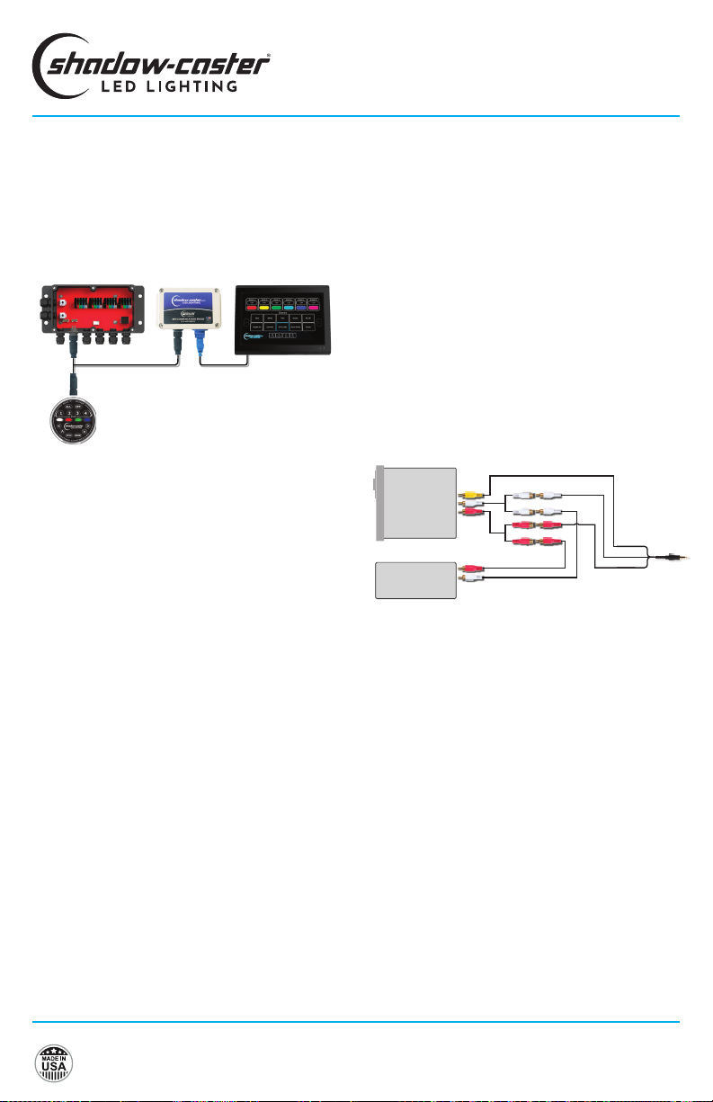
ADDING ADDITIONAL REMOTES AND
MULTI-FUNCTION DISPLAYS
Additional SCM-ZC-REMOTES can be added to your
installation with our Y-cable and 1m, 2m & 4m extension
cables. See Optional Parts section below for details.
SCM-MFD-BRIDGE MFDSCM-MZ-LC
SCM-ZC-REMOTE
CONNECTING STEREO INPUT FOR
STEREO MUSIC SYNC INPUT
Stereo
Amp To 3.5mm
Female Audio
Jack Input
RCA (Phono)
Cables & Splitters
BEST PRACTICES FOR MITIGATING
NOISE ISSUES
Noise interface is common in systems with RGB
lighting controls and amplied stereo systems. The
advanced circuitry in the lighting controller does
everything possible to protect from this.
Utilizing installation best practices will further mitigate
these issues.
1. Make sure to supply ample gauge power and sepa-
rate distribution points from stereo power.
2. Run RGB power wires as far as possible from the
speaker feeds for the stereo. Run separate bundles
where possible.

SCM-MFD-LC-KIT
OPERATION MANUAL
Shadow-Caster®LED Lighting | 2060 Calumet Street. | Clearwater, FL 33765
p: 1+ 727.474.2877 e: info@shadow-caster.com w: shadow-caster.com
12
SCM-MZ-LC NOT LIGHTING UP
When power is rst applied to the lighting controller, the
box will ash blue very briey.
Once it receives a valid control input from a connected
controller it will stay blue continuously. If it is not light-
ing up please double check for correct orientation and
reseat the SC-NET cable.
SHADOW-NET®LIGHTS WILL OCCASIONALLY
LOCK UP AND STOP RECEIVING MESSAGES
This indicates that there is a noise issue on the
Shadow-NET®communication lines. Typically this is
caused by insucient gauge wire feeding one or more
Shadow-NET®connected lights.
MY SHADOW-NET®LIGHTS STAY ON
If the connected Shadow-NET®lights are not turning
off at initial power up then there is a challenge with the
Shadow-NET®connection.
Check the orange and yellow wire connections are not
reversed and are fully connected.
TROUBLESHOOTING
MFD CONNECTION TROUBLESHOOTING
MY SYSTEM IS NOT CONNECTING:
Remove 4 screws on top of SCM-MFD-BRIDGE. Verify
that the blue power light is on. This indicates a bad con-
nection on the 4 pin cable from the lighting controller
Verify that the red and green communication lights
are coming on and blinking. This will verify that the
Ethernet connection is good, and communication is
established.
MUSIC SYNC NOT WORKING
Verify that an appropriate 3.5mm stereo jack is being
used and that there is a usable signal.
If a separate output zone is used, verify that the output
is enabled and the output is set to a usable volume.
It is not recommended to use a subwoofer output, as
certain sync modes require the full audio range.
MY SYSTEM HAS A "BOOT LOADER ERROR"
This is typically a problem with multi-screen installation
and indicates that a POE isolator is needed.

Shadow-Caster®LED Lighting |2060 Calumet Street. |Clearwater, FL 33765
p: 1+ 727.474.2877 e: info@shadow-caster.com w: shadow-caster.com
Designed & Manufactured
in Clearwater, FL
© 2021 Shadow-Caster®LED Lighting, All Rights Reserved
AUG21
Table of contents
Other Shadow-Caster Boating Equipment manuals

Popular Boating Equipment manuals by other brands

Pfeiffer
Pfeiffer LAZY JACK System I quick start guide

marinco
marinco 10105 installation instructions

Scheiber
Scheiber BLOC 10 User & Troubleshooting Guide

Sunstream
Sunstream BOAT LIFTS FL13018 Assembly and installation manual

Taylor Made
Taylor Made BIMINI Assembly instructions

Taco Marine
Taco Marine M20-1013A Assembly instructions


Humphree
Humphree Lightning installation manual

Vetus
Vetus BOW9512C Operation manual and installation instructions

Made Engineered
Made Engineered Romar Leisure Furl furling boom owner's manual

Humphree
Humphree LIGHTNING INTERCEPTOR Operator's manual

CMC
CMC Typhoon Tower owner's manual

Lewmar
Lewmar LFX Assembly Instructions & Safe Anchoring Guide