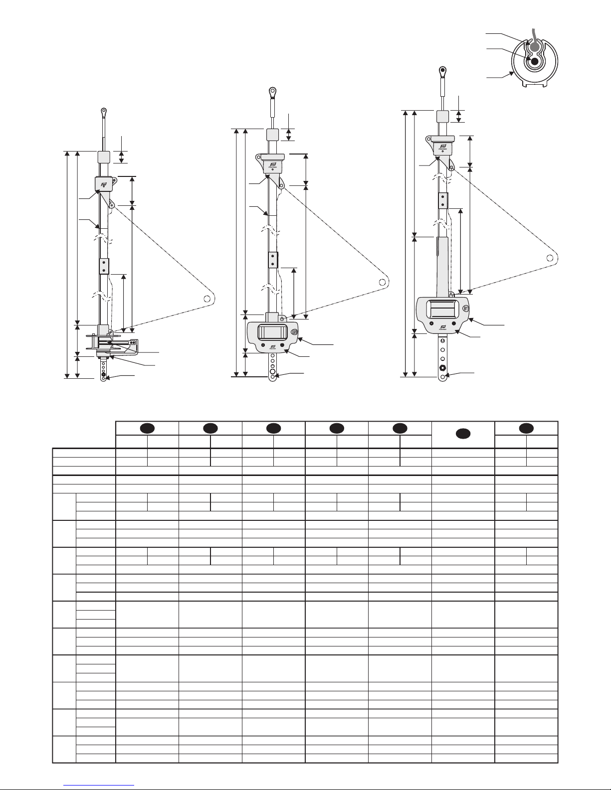
Plastimo 406-S User manual

406-S 609-S 811-S
GB
D
NL
S
I
E
F
ROLLREFFANLAGE - AUFBLASBARE RETTUNGSWESTEN
ROLREEFSYSTEEM - GEBRUIKERSHANDLEIDING
RULLFOCKSYSTEM - INSTRUKTIONER OCH HANDHAVANDE
ENROLLADOR - GUIA DE UTILIZACION
JIB REEFING - OWNER'S MANUAL
AVVOLGITORE - MANUALE D'USO
ENROULEUR DE FOC - NOTICE D'UTILISATION
Plastimo - 15, rue Ingénieur Verrière - 56100 Lorient - FRANCE
PANTONE 425C
Couché moderne brillant 200g
58223_00 - Page 1/76

58223_00 - Page 2/76
PANTONE 425C
Couché moderne brillant 200g

IDF
GB S
ENL
latte Terminal-
montage
chainplate ridoirturnbuckle
406-S
609-S
811-S
25722 25722 25722 25722 2572225722
58202 58202 58202 58202 58202 58202
58204 58204 58204 58204 58204 58204 58204
25723 25723 25723 25723 25723 2572325723
58203 58203 58203 58203 58203 58203 58203
ØA
ØB étai : Ø4-7mm Vorstag : Ø4-7mm voorstag : Ø4-7mm estay : Ø4-7mm Förstags : Ø4-7mm Strallo : Ø4-7mmforestay : Ø4-7mm ralingue :Ø6.5mm Vorliek :Ø6.5mm voorlijk :Ø6.5mm relinga :Ø6.5mm Lik :Ø6.5mm ralinga :Ø6.5mmluffrope : Ø6.5mm
811-S
407-S
609-S
C6.20m 6.20m 6.20m 6.20m 6.20m6.20m 6.28m 6.28m 6.28m 6.28m 6.28m 6.28m6.28m 9.22m 9.22m 9.22m 9.22m 9.22m9.22m 9.40m 9.40m 9.40m 9.40m 9.40m 9.40m9.40m 11.05m 11.05m 11.05m 11.05m 11.05m 11.05m11.05m
811-S
407-S
609-S
D
2
12m 2
12m 2
12m 2
12m 2
12m 2
12m
2
12m 2
25m 2
25m 2
25m 2
25m 2
25m 2
25m
2
25m 2
35m 2
35m 2
35m 2
35m 2
35m 2
35m
2
35m
E
811-S
407-S
609-S 65mm 65mm 65mm 65mm 65mm 65mm150mm 150mm 150mm 150mm 150mm 150mm 150mm
115mm 115mm 115mm 115mm 115mm115mm 285mm 285mm 285mm 285mm 285mm 285mm285mm
220mm 220mm 220mm 220mm 220mm 220mm220mm
811-S
407-S
609-S
F5.82m 5.82m 5.82m 5.82m 5.82m 5.82m5.82m 8.80m 8.80m 8.80m 8.80m 8.80m 8.80m8.80m 10.49m 10.49m 10.49m 10.49m 10.49m 10.49m10.49m
G
811-S
407-S
609-S 1 gorge 1 Nuten 1 zeilgroeven 1 relingas 1 likrännor 1 gole1 groove
811-S
407-S
609-S
ØH 8.5mm 8.5mm 8.5mm 8.5mm 8.5mm 8.5mm8.5mm 12.5mm 12.5mm 12.5mm 12.5mm 12.5mm 12.5mm12.5mm 14.3mm 14.3mm 14.3mm 14.3mm 14.3mm 14.3mm14.3mm
J
811-S
407-S
609-S jonctions aluminium
+ vis Verbindungen Alu-
minium +Schrauben koppelstuk
alu + schroeven Empalmes aluminio
+ tornillos Kopplïngar alumi-
nium + skruv Giunzione aluminio
+ vite
coupling units :
aluminium+screws
R1811-S
407-S
609-S roulement Delrin Kugellager Delrin lagering Delrin Rodamientos Delrin Kullager Delrin cuscinetti Delrinbearing: Delrin roulement Delrin,inox Kugellager Delrin,inox lagering Delrin,RVS Rod. Delrin,inox Kulla. Delrin,rostfritt cuscinetti Delrin,inoxbearing: Delrin,inox roulement Delrin, Torlon Kugellager Delrin, Torlon lagering Delrin, Torlon Rod. Delrin, Torlon Kulla. Delrin, Torlon cusci. Delrin, Torlonbearing: Delrin, Torlon
R2
811-S
407-S
609-S roulement Delrin Kugellager Delrin lagering Delrin Rodamientos Delrin Kullager Delrin cuscinetti Delrinbearing: Delrin
roulement
Delrin, Torlon Kugellager
Delrin, Torlon lagering
Delrin, Torlon Rodamientos
Delrin, Torlon Kullager
Delrin, Torlon cuscinetti
Delrin, Torlon
bearing:
Delrin, Torlon
811-S
407-S
609-S
S
5.95m 5.95m 5.95m 5.95m 5.95m 5.95m5.95m 8.94m 8.94m 8.94m 8.94m 8.94m 8.94m8.94m 10.44m 10.44m 10.44m 10.44m 10.44m 10.44m10.44m
Stagspanner-
montage stevenplaa-
tuitvoering spanschroe-
fuitvoering placas tensor Landre Arridatoi
120
C
D
45
ØA
ØB
Ø31
110
435
Ø145
ØH
F
E
406-S 609-S 811-S
S
R1
R2
J
S
45
R1
Ø190
ØH
E
C
136 D
421
F118
R2
J
118
R2
45
S
R1
Ø200
ØH
E363
C
605
F
D
- 3 -
58223_00 - Page 3/76
PANTONE 072C
Offset 80g

406-S 2
3
4
5x2
6
7x4
8
9x8
x4
10
12
13
14b
1
11 x4
x3
14a
- 4 -
15
x15
DFGB S
ENL
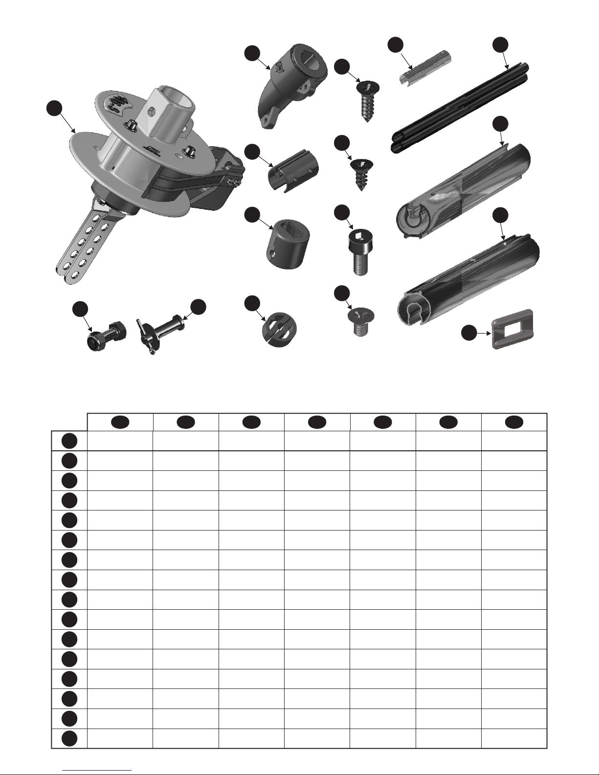
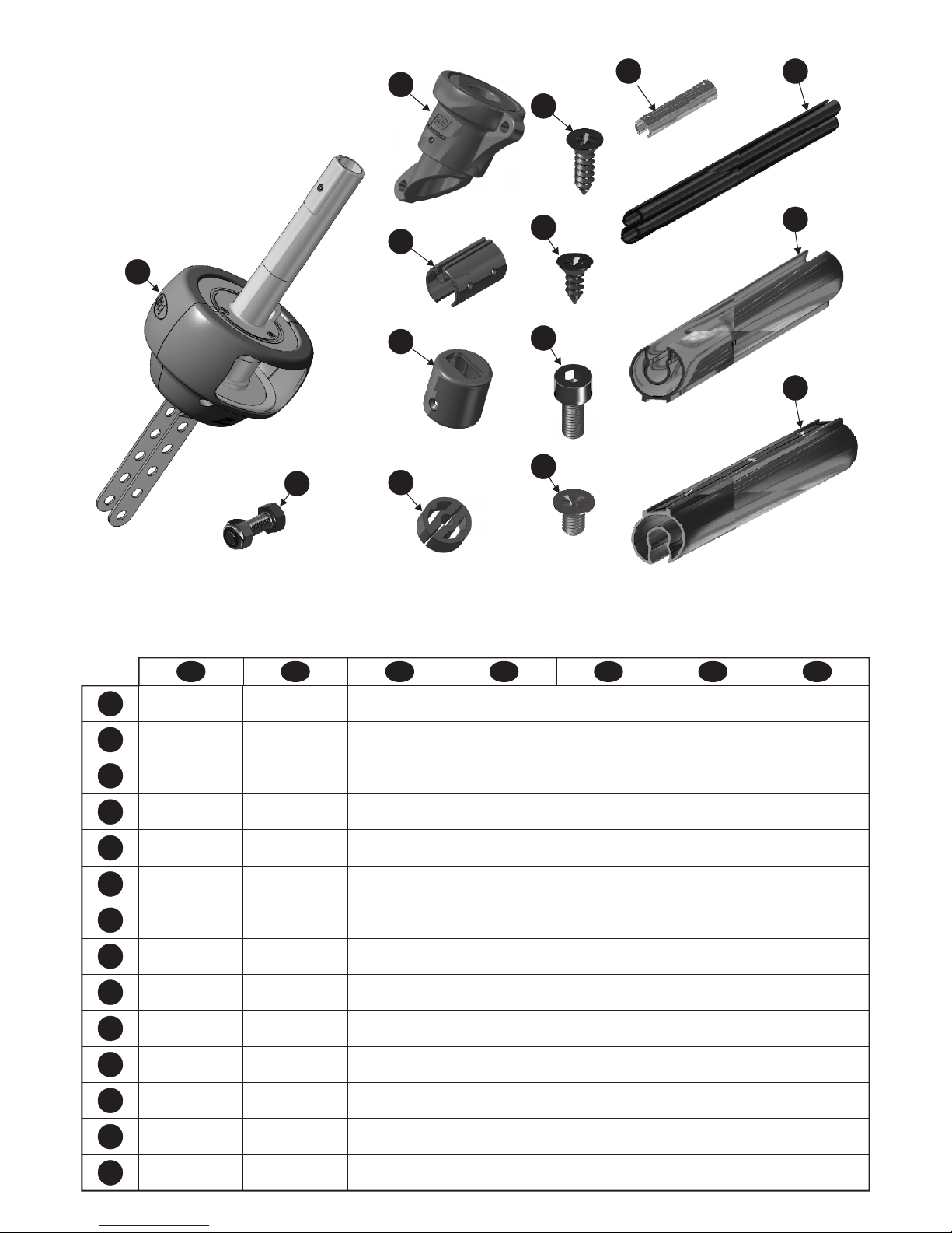
4 Coupling sleeves 4 pièces de jonction
aluminium 4 Verbindungsstücke 4 koppelstukken 4 piezas de uniones 4 Skarvstycken 4 Pezzi di giunzione
4 PVC liners 4 profils PVC 4 PVC-Profile 4 PVC binnenprofielen 4 Perfiles PVC 4 Innerprofil i PVC
- plastrofil 4 Profilati PVC
1 base spar 1 profil aluminium
bas 1 unteres Profil 1 basisprofiel 1 perfil bajo 1 Bottenprofil 1 profilato basso
3 Intermediate spars 3 profils aluminium
intermédiaires 3 Zwischenprofile 3 standaardprofielen 3 Perfiles intermedios 3 Standard profiler 3 Profilati intermedi
1 screw+nut M8x35
=>chainplate 1 vis+écrou M8x35
modèle lattes 1 Schraube M8x35
Terminalmontage 1 bunten M8x35
stevenplaatuitvoering 1 tornillo M8x35
(placas) 1 M8x35insex 1 Vite M8x35
Modello Landre
1 Shoudered clevis pin
Ø8 (=>turnbuckle) 1 axe épaulé Ø8
modèle ridoir 1 Bolzen, dick Ø8
Stagspannermontage 1 pen Ø8
spanschroefuitvoering 1 Bulón Ø8
(tensor) 1 Riggbult Ø8 1 Asse a testa Ø8
Modello arridatoi
15 15 PVC slide
(=>turnbuckle) 15 coulisseau plastique
modèle ridoir 15 PVC Rutscher
Stagspannermontage 15 PVC-leuver
spanschroefuitvoering 15 patin
(tensor) 15 Plasttravare 15 guida in plastica
Modello arridatoi
1 drum unit 1 ensemble tambour 1 Trommel 1 roltrommel 1 conjunto tambor 1 Trumma med
revlinematare 1 insieme tamburo
1 boltrope prefeeder 1 guide ralingue 1 Liekeinführung 1 voorlijkinvoer 1 guía relinga 1 Segelinmatare 1 guida ralinga
1 top end stop 1 embout profil 1 Profilansatzstück 1 top eind stuk 1 terminal tope 1 Toppdel 1 Terminale profilato
2 bearings 2 paliers de profil 2 Stopper 2 lagers 2 cojinetes 2 Lagringar 2 Supporti
4 screws Ø3.9x9.5
(prefeeder) 4 vis tôle TF Ø3.9x9.5
fixation guide ralingue 4 Schraube Ø3.9x9.5
(Liekeinführung) 4 schroeven Ø3.9x9.5
(voorlijkinvoer) 4 tornillos Ø3.9x9.5
(guía relinga) 4 spårskruv Ø3.9x9.5
(Segelinmatare) 4 viti lamiera Ø3.9x9.5
(guida ralinga)
1 Ø4.8x12.
(top end stop)
screw 1 vis tôle TF Ø4.8x12.
fixation embout profil 1 Ø4.8x12.
(Profilansatzstück)
Schraube 1 schroef Ø4.8x12.
(top eind stuk ) 1 tornillo Ø4.8x12.
(terminal tope) 1 spårskruv Ø4.8x12.
(Toppdel) 1 vite lamiera Ø4.8x12
(terminale profilato)
1 M5x12
(base spar)
screw 1 vis Chc M5x12
fixation profil bas 1 M5x12
(unteres Profil)
Schraube 1 M5x12
(basisprofiel)
schroef 1 tornillo M5x12
(perfil bajo) 1 insex M5x12
(Bottenprofil) 1 vite a brugola M5x12
(profilato basso)
8 M5x8
(spar connections)
screws 8 vis TF M5x8
liaison profils 8 Schraube M5x8
(Verbindung der Profile) 8 bouten M5x8
(koppelstukken ) 8 Tornillos M5x8
(unión perfiles) 8 M5x8
(profilkopplingarna)
insex 8 vite M5x8
(collegamento profilati)
1 halyard swivel 1 émerillon 1 Fallwirbel 1 valwartel 1 giratorio 1 Fallsvirvel 1 mulinello
I
2
3
4
5
6
7
8
9
10
12
13
14b
14a
11
1
58223_00 - Page 4/76
PANTONE 072C
Offset 80g

609-S 2
3
4
5x2
6
7x4
8
9x12
x6
10
12
13
14b
1
11 x6
x5
14a
- 5 -
15
x15
DFGB S
ENL
6 Coupling sleeves 6 pièces de jonction
aluminium 6 Verbindungsstücke 6 koppelstukken 6 piezas de uniones 6 Skarvstycken 6 Pezzi di giunzione
6 PVC liners 6 profils PVC 6 PVC-Profile 6 PVC binnenprofielen 6 Perfiles PVC 6 Innerprofil i PVC
- plastrofil 6 Profilati PVC
1 base spar 1 profil aluminium
bas 1 unteres Profil 1 basisprofiel 1 perfil bajo 1 Bottenprofil 1 profilato basso
5 Intermediate spars 5 profils aluminium
intermédiaires 5 Zwischenprofile 5 standaardprofielen 5 Perfiles intermedios 5 Standard profiler 5 Profilati intermedi
1 screw+nut M12x35
=>chainplate 1 vis+écrou M12x35
modèle lattes 1 Schraube M12x35
Terminalmontage 1 bunten M12x35
stevenplaatuitvoering 1 tornillo M12x35
(placas) 1 M12x35insex 1 Vite M12x35
Modello Landre
1 Shoudered clevis pin
Ø12 (=>turnbuckle) 1 axe épaulé Ø12
modèle ridoir 1 Bolzen, dick Ø12
Stagspannermontage 1 pen Ø12
spanschroefuitvoering 1 Bulón Ø12
(tensor) 1 Riggbult Ø12 1 Asse a testa Ø12
Modello arridatoi
15 15 PVC slide
(=>turnbuckle) 15 coulisseau plastique
modèle ridoir 15 PVC Rutscher
Stagspannermontage 15 PVC-leuver
spanschroefuitvoering 15 patin
(tensor) 15 Plasttravare 15 guida in plastica
Modello arridatoi
1 drum unit 1 ensemble tambour 1 Trommel 1 roltrommel 1 conjunto tambor 1 Trumma 1 insieme tamburo
1 boltrope prefeeder 1 guide ralingue 1 Liekeinführung 1 voorlijkinvoer 1 guía relinga 1 Segelinmatare 1 guida ralinga
1 top end stop 1 embout profil 1 Profilansatzstück 1 top eind stuk 1 terminal tope 1 Toppdel 1 Terminale profilato
2 bearings 2 paliers de profil 2 Stopper 2 lagers 2 cojinetes 2 Lagringar 2 Supporti
4 screws Ø3.9x9.5
(prefeeder) 4 vis tôle TF Ø3.9x9.5
fixation guide ralingue 4 Schraube Ø3.9x9.5
(Liekeinführung) 4 schroeven Ø3.9x9.5
(voorlijkinvoer) 4 tornillos Ø3.9x9.5
(guía relinga) 4 spårskruv Ø3.9x9.5
(Segelinmatare) 4 viti lamiera Ø3.9x9.5
(guida ralinga)
1 Ø4.8x12.
(top end stop)
screw 1 vis tôle TF Ø4.8x12.
fixation embout profil 1 Ø4.8x12.
(Profilansatzstück)
Schraube 1 schroef Ø4.8x12.
(top eind stuk ) 1 tornillo Ø4.8x12.
(terminal tope) 1 spårskruv Ø4.8x12.
(Toppdel) 1 vite lamiera Ø4.8x12
(terminale profilato)
1 M5x12
(base spar)
screw 1 vis Chc M5x12
fixation profil bas 1 M5x12
(unteres Profil)
Schraube 1 M5x12
(basisprofiel)
schroef 1 tornillo M5x12
(perfil bajo) 1 insex M5x12
(Bottenprofil) 1 vite a brugola M5x12
(profilato basso)
12 M5x8
(spar connections)
screws 12 vis TF M5x8
liaison profils 12 Schraube M5x8
(Verbindung der Profile) 12 bouten M5x8
(koppelstukken ) 12 Tornillos M5x8
(unión perfiles) 12 M5x8
(profilkopplingarna)
insex 12 vite M5x8
(collegamento profilati)
1 halyard swivel 1 émerillon 1 Fallwirbel 1 valwartel 1 giratorio 1 Fallsvirvel 1 mulinello
I
2
3
4
5
6
7
8
9
10
12
13
14b
14a
11
1
58223_00 - Page 5/76
PANTONE 072C
Offset 80g

811-S 2
3
4
5x2
6
7x4
8
9x14
x7
10
12
13
1
11 x7
x6
14
- 6 -
14
DFGB S
ENL
7 Coupling sleeves 7 pièces de jonction
aluminium 7 Verbindungsstücke 7 koppelstukken 7 piezas de uniones 7 Skarvstycken 7 Pezzi di giunzione
7 PVC liners 7 profils PVC 7 PVC-Profile 7 PVC binnenprofielen 7 Perfiles PVC 7 Innerprofil i PVC
- plastrofil
1 base spar 1 profil aluminium
bas 1 unteres Profil 1 basisprofiel 1 perfil bajo 1 Bottenprofil 1 profilato basso
6 Intermediate spars 6 profils aluminium
intermédiaires 6 Zwischenprofile 6 standaardprofielen 6 Perfiles intermedios 6 Standard profiler 6 Profilati intermedi
1 screw+nut M14x40 1 vis+écrou M14x40 1 Schraube M14x40 1 bunten M14x40 1 tornillo M14x40 1 M14x40insex
1 drum unit 1 ensemble tambour 1 Trommel 1 roltrommel 1 conjunto tambor 1 Trumma 1 insieme tamburo
1 boltrope prefeeder 1 guide ralingue 1 Liekeinführung 1 voorlijkinvoer 1 guía relinga 1 Segelinmatare
1 top end stop 1 embout profil 1 Profilansatzstück 1 top eind stuk 1 terminal tope 1 Toppdel 1 Terminale profilato
2 bearings 2 paliers de profil 2 Stopper 2 lagers 2 cojinetes 2 Lagringar
4 screws Ø3.9x9.5
(prefeeder) 4 vis tôle TF Ø3.9x9.5
fixation guide ralingue 4 Schraube Ø3.9x9.5
(Liekeinführung) 4 schroeven Ø3.9x9.5
(voorlijkinvoer) 4 tornillos Ø3.9x9.5
(guía relinga) 4 spårskruv Ø3.9x9.5
(Segelinmatare) 4 viti lamiera Ø3.9x9.5
(guida ralinga)
1 Ø4.8x12.
(top end stop)
screw 1 vis tôle TF Ø4.8x12.
fixation embout profil 1 Ø4.8x12.
(Profilansatzstück)
Schraube 1 schroef Ø4.8x12.
(top eind stuk ) 1 tornillo Ø4.8x12.
(terminal tope) 1 spårskruv Ø4.8x12.
(Toppdel) 1 vite lamiera Ø4.8x12
(terminale profilato)
1 M5x12
(base spar)
screw 1 vis Chc M5x12
fixation profil bas 1 M5x12
(unteres Profil)
Schraube 1 M5x12
(basisprofiel)
schroef 1 tornillo M5x12
(perfil bajo) 1 insex M5x12
(Bottenprofil) 1 vite a brugola M5x12
(profilato basso)
14 M5x8
(spar connections)
screws 14 vis TF M5x8
liaison profils 14 Schraube M5x8
(Verbindung der Profile) 14 bouten M5x8
(koppelstukken ) 14 Tornillos M5x8
(unión perfiles) 14 M5x8
(profilkopplingarna)
insex 14 vite M5x8
(collegamento profilati)
1 halyard swivel 1 émerillon 1 Fallwirbel 1 valwartel 1 giratorio 1 Fallsvirvel
7 Profilati PVC
1 Vite M14x40
1 guida ralinga
2 Supporti
1 mulinello
I
2
3
4
5
6
7
8
9
10
12
13
11
1
58223_00 - Page 6/76
PANTONE 072C
Offset 80g

ASSEMBLY INSTRUCTIONS
FOR S-SERIES
406-S 609-S 811-S
- 7 -
I N D E X
1/ TECHNICAL SPECIFICATIONS 406-S, 609-S, 811-S 3
2/ DESCRIPTION OF SPECIFIC PARTS FOR EACH MODEL
2.1 - 406-S 4
2.2 - 609-S 5
2.3 - 811-S 6
3/ TOOLS NEEDED 7
4/ FLAT ASSEMBLY (forestay dismantled)) 7
4.1 - Dismantling the forestay 8
4.2 - Assembly of the jib reefing system 9
4.3 - Assembling the last spar 9
4.4 - Assembling the top end stop 10
5/ IN SITU ASSEMBLY (directly onto the boat) 10
5.1 - Measuring the length of the forestay 10
5.2 - Cutting the last spar 11
5.3 - Assembling the top end stop 11
5.4 - Assembling the spars 11
5.5 - Assembling the base spar 12
5.6 - Cutting the PVC liner 12
5.7 - Assembling the boltrope prefeeder 12
5.8 - Assembling the drum unit 13
5.9 - Adjusting the reefing line feeders 13
6/ RECOMMANDATIONS 14
7/ OPTIONAL EXTRAS 15
8/ SPARE PARTS
8.1 - 406-S 72
8.2 - 609-S 73
8.3 - 811-S 74
3/ TOOLS NEEDED
Tools needed :
- Hammer
- Pliers
- Comfortable bosun's chair (Plastimo).
- Allen key (4)
- Electric or hand drill
- 1 Ø4 mm drill
- Hacksaw
- Tape measure
- Screwdriver
- Silicone filler.
4/ FLAT ASSEMBLY
- This method consists of fully dismantling the forestay and assembling the jib reefing system while the forestay is lying flat.
- We recommend this method as it is faster.
- In certain cases the top part of the forestay cannot be dismantled, in this case::
do an in situ assembly (see page 10)
contact a professional who can install a universal joint on the upper part of the forestay.
GB
58223_00 - Page 7/76
PANTONE 072C
Offset 80g

- 8 -
4.1 - Dismanting the forestay
4.1.1 - Lower part
- Slacken the backstay
- Secure the mast forward with 1 or 2 halyards
- Tigthen the halyards to relieve the strain on the forestay
- Dismantle the lower part of the forestay (this usually consists of removing a removing a
rigging screw pin, or a screw and a nut).
Note : it is important to measure the distance between the forestay eye and the hole of the
forward mounting plate in order to find the correct adjustments again.
For a turnbuckle assembly, measure the distance between the mounting plate and the blocking
nut of the turnbuckle.
4.1.2 - Upper part
- Send a person to the masthead (equipped with hammer and pliers)
- Dismount the upper part of the forestay
- Bring the person and the forestay down from the masthead
halyard to
secure the mast
forestay
slackened
backstay
halyard to
secure the mast
forestay
slackened
backstay
4.2 - ASSEMBLING THE JIB REEFING SYSTEM
- Lay the forestay flat
- Place the parts to be assembled alongside the forestay
- Assemble the drum unit on the forestay and put the rigging screw pin or screw and nut in place (select the chainplate hole that
corresponds to the initial forestay adjustment).
- Slide a bearing into the drum
- Insert a coupling sleeve into the base spar (ensure that the hole in the coupling sleeve is in line with the pre-drilled hole of the base
spar)
58223_00 - Page 8/76
PANTONE 072C
Offset 80g

GB
- 9 -
- Slide the base spar into the drum unit until the two holes are in line, insert the M5x12 screw (after putting some silicone filler in the
hole in order to reduce the stainless steel / aluminium electrolytic couple) and tighten.
- Secure with the 4 screws ø3.9x9.5
- Install the boltrope prefeeder; ensure it is the right way up, see diagram below.
- Insert an aluminium coupling sleeve, put some silicone filler into the hole and position a MSx8 screw (do not tighten or it will be
difficult to put the second screw in place).
- Put a second spar into position, put some silicone filler in the hole and position the screw (once the two screws are in position they
may both be tightened). Wipe off any excess filler with a cloth.
- Insert PVC liners as you go along (ensure they are flush against the prefeeder)
- Repeat the process until only one spar is left
4.3 Cutting the last spar
- Position the last spar so that it lies flush against the previous spar but do not install it
- Measure a distance of 5 cm back from the sleeve of the forestay
- Mark and cut the spar with a hacksaw
- Put a coupling sleeve into position
- Insert the spar, then insert and tighten the screw
5cm
- Position the last PVC liner
- Mark the liner level with the end of the aluminium spar
- Cut and insert the PVC liner
58223_00 - Page 9/76
PANTONE 072C
Offset 80g

- 10 -
4.4 Installing the top end stop
- Slot the second bearing into the top end stop
- Slide the top end stop over the aluminium spar
- Drill a hole (with a Ø4 mm drill). IMPORTANT: refer to diagram for the positioning of the top end stop
- Before putting the screw into position, do not forget to slide the halyard swivel into place (ensure that the conical end of the halyard
swivel faces downwards)
- Put the top end stop back into position
- Put some silicone filler into the hole
- Insert and tighten screw Ø4.8 x 12.7
- Your jib reefing system is now assembled and can be put into position (hoist it up to the masthead with a halyard)
5/ IN SITU ASSEMBLY
Øthis method of assembly may be carried out by one person
Øit is not necessary to dismantle anything at the masthead
5.1 - MEASURING THE LENGTH OF THE FORESTAY
In order for this jib reefing system to be perfectly adapted to your boat the length « X » needs to be known.
- Slide a small shackle around the forestay
- Ensure that it lies flush against the sleeve
- Slacken the backstay
- Secure the mast with a halyard
- Dismount the lower part of the forestay
- Assemble the drum unit
- Reassemble the lower part of the forestay
- Undo the halyard and tighten the backstay
- Attach a halyard to the shackle
- Attach a length of rope (or a tape measure) to the shackle
- Hoist the shackle until it touches the top sleeve of the forestay
- Mark the piece of rope level with the top of the drum unit
- Lower the shackle
58223_00 - Page 10/76
PANTONE 072C
Offset 80g

- 11 -
XX
5.2 - CUTTING THE LAST SPAR
- Stretch out flat the piece of rope used to measure the length of the forestay
- Lay the aluminium spars parallel to the piece of rope (take note of base spar, see page 7)
- Mark the spar level with the mark on the piece of rope
- Cut the spar 3 cm (safety margin) below the mark
3cm
X
5.3 - ASSEMBLING THE TOP END STOP
- The top end stop should be assembled on the aluminium spar that has just been cut.
a) The second bearing is slotted into the top end stop
b) Slide the top end stop fully over the end of the spar (IMPORTANT: refer to diagram below for positioning of the hole in the top end
stop)
c) Drill a hole using a Ø4 mm drill
5.4 - ASSEMBLING THE SPARS
- Dismount the forestay from the stemhead fitting
- Install the following on the forestay :
Top end stop
Bearing
The spar that you have cut and drilled
1 screw Ø4.8x12.7
PVC liner
Halyard swivel (IMPORTANT: see drawing below for position of halyard swivel)
58223_00 - Page 11/76
PANTONE 072C
Offset 80g
GB

- 12 -
- Refasten the forestay
- Attach a halyard to the halyard swivel in order to support the spars as they are assembled
- Insert a coupling sleeve
- Put some silicone filler into the holes before tightening the screws (in order to reduce the electrolytic couple between the stainless steel
screw and the aluminium)
- Insert an M5 x 8 screw
- Wipe away any excess silicone with a cloth
- Slide another aluminium spar into position
- Insert a PVC liner (IMPORTANT: keep the base spar to one side; you will be assembling it last)
- Repeat the process as many times as necessary
5.5 - ASSEMBLING THE BASE SPAR
EIMPORTANT: ensure the base spar is facing the right way (see diagram below)
holes to secure prefeeder
end to be inserted
into drum
5.6 - CUTTING THE PVC LINER
- Slide the prefeeder into position from the bottom of the spar until it is in line with the holes in the spar (IMPORTANT: ensure that the
prefeeder is the right way up)
- Insert a Ø3.9x9.5 screw
- Position a PVC liner, mark and cut to required length
- Remove the prefeeder and install the cut PVC liner
5.7 - INSTALLING THE BOLTROPE PREFEEDER
- Put the prefeeder back into position
- Put some silicone filler in the holes
- Insert and tighten the 4 Ø3,9x9,5 screws
- Wipe away any excess filler with a cloth
58223_00 - Page 12/76
PANTONE 072C
Offset 80g

- 13 -
GB
5.8 - ASSEMBLING THE DRUM UNIT
- Detach the forestay from its mounting plate on the boat
- Position the sleeve or turnbuckle* on the drum (*depending on model)
- Slide a bearing into the drum
- Insert a coupling sleeve into the base spar (ensure that the hole in the coupling sleeve is in line with the
pre-drilled hole of the base spar)
- Insert the base spar into the drum unit
- Put some silicone filler in the pre-drilled hole
- Insert the M5x12 screw
- Attach the jib reefing system to the forward mounting plate
- Lower the halyard swivel
- Tighten the backstay
5.9 - ADJUSTING THE REEFING LINE FEEDERS
5.9.1 - 406-S model
- The reefing line feeder on the 406-S model is assembled either on the right or left hand side of the drum unit, depending on which
direction you prefer to reef.
- To fasten the reefing line feeder, use the two M4x12 nuts and bolts
5.9.2 - 609-S & 811-S models
- The angle of reefing line feeders on 609-S & 811-S models is adjusted by loosening the two nuts and bolts (see diagram below)
Screws
- The angle is adjusted by loosening the two screws that hold the chainplate.
port assemblystarboard assembly
58223_00 - Page 13/76
PANTONE 072C
Offset 80g

- 14 -
6/ Recommandations
AReefing line feeders
The angle of all the reefing line feeders may be adjusted.
IMPORTANT: they should be positioned in a way that best suits
the direction of pull on the line
AReefing line
The reefing line is wound around the drum. Only use pre-stretched rope in order to eliminate
any elasticity
Refer to diagram below for the position of the reefing line as it comes out of the drum
1m
90°
AReefing direction of the genoa
The genoa should be reefed in the same direction as the strands turn on the forestay.
AWhen you are not sailing
Slacken the backstay in order to reduce undue strain on mechanical parts
AAbout the drum
When your genoa is fully reefed and in order to avoid direct strain on mechanical parts and on the knot of the reefing line, there should be a
minimum length of one halyard turn on the drum.
AHalyard/forestay angle
This angle should never be more than 20-25° as this makes it impossible to tauten and reef the sail.
What is more, this undue strain on the forestay could cause it to unravel and even dismast the boat.
AWhen sailing
Ensure that the forestay is always taut. Not only will this make reefing easier but will avoid any danger of the forestay unravelling.
(We recommend putting a universal joint at the masthead)
AHauling on the genoa
The reefing line should never be used to haul on the sail.
AUnfurling the genoa
When unfurling the genoa, ensure that it does not unfurl too quickly by winding the reefing line once round a winch and feeding it out
slowly in one hand and the genoa sheet in the other.
AMaintenance
Rinse the drum unit and the halyard swivel once a year
with fresh water (no dismantling required).
No other special maintenance is needed.
Fresh water
58223_00 - Page 14/76
PANTONE 072C
Offset 80g

- 15 -
Genoa difficult to hoist - Poor output from a sheave.
Halyard jammed
- Luffrope too large
- Try with a different halyard
- Change luffrope
PROBLEM ENCOUNTERED CAUSES SOLUTIONS
Halyard turns with the halyard swivel - Forestay not taut enough
- Genoa halyard too slack
- Genoa too short, halyard swivel too low
- tighten the backstay
- tauten the genoa halyard
- Use a strop
- Genoa halyard too close to the forestay - Fasten a halyard feeder to the mast or a
diverter to the forestay
The halyard tends to wrap itself around the
spar when the genoa is hoisted - Halyard is worn and thus twists in the
direction of the rope strands
- Change the halyard
Reefing line fouls - Wrong angle on reefing line.
First sheave too far from drum unit.
- Genoa unfurled too quickly
- Change position of first sheave
- Slow down the unfurling of the genoa by
winding the reefing line once round a winch.
7/ OPTIONAL EXTRAS
7.1 - HALYARD DIVERTERS
When the genoa is furled or unfurled, if the angle between the halyard and the forestay is too tight, the halyard risks being twisted round as
the halyard swivel turns.
2 options are available to solve this problem:
7.1.1 : Halyard diverter wheel
To install the diverter wheel, it is necessary to dismantle the forestay
7.1.2 : Halyard feeder
To install the halyard feeder, it is not necessary to dismantle the forestay
2 sizes are available:
- ref 25677 : 609 et 811 models
- ref 26140 : 406 model
Ref : 25720
Ref : 25677 Ref : 26140
GB
58223_00 - Page 15/76
PANTONE 072C
Offset 80g
Other manuals for 406-S
1
This manual suits for next models
2
Table of contents
Other Plastimo Boating Equipment manuals
Popular Boating Equipment manuals by other brands

Furuno
Furuno FELCOM 250 Operator's manual

monster tower
monster tower HS1 Installation instructions and owner's manual

Kongsberg
Kongsberg SIMRAD TillerPilots TP10 manual

Garelick
Garelick 74002 Assembly and installation instructions

Seakeeper
Seakeeper 8000 GYRO Operation manual

Spinlock
Spinlock DECKVEST DURO manual