Shaktiman Fertilizer Broadcaster User manual

O P E R A T O R ’S M A N U A L
FERTILIZER BROADCASTER
OM: 2011/Rev 01/2015

O P E R A T O R ’S M A N U A L
FERTILIZER BROADCASTER
MISSION:
Our mission is to manufacture & supply the most technologically advanced agricultural
machinery & implements, worldwide, with acknowledged reliability, outstanding quality
and with support by excellent services.
STRATEGY:
Our strategy is to provide best quality with customer delight on all parameters of
agricultural machinery & implements, services and reach.
MANUFACTURER
Tirth Agro Technology Pvt. Ltd.
!"#$%!&'()*#
+!&#!',-#!&./+0#
.$123#45/#
6&47&457'!#
+/89:(9
;<1,),-3:::9-#,-(=9-;<1,),-3,-(>=-&
???&6.&

,
To the Purchaser
This manual contains valuable information about your SHAKTIMAN FERTILIZER
BROADCASTER. It has been carefully prepared to give you helpful suggestions for
operating, adjusting, servicing repair parts.
Keep this manual in a convenient place for quick and easy reference. Study it carefully.
You have purchased a dependable and sturdy implement, but only by proper care and
operation can you expect to receive the service and long life designed and built into it.
RIGHT-HAND AND LEFT-HAND sides are determined by watching from the tractor
side.
Sometime in the future your implement may need new parts to replace those that are
worn or broken. If so, go to your dealer and provide him with the model and part number.
Customer information
Name
Purchased from
Purchased date
Model No.
Serial No.

9
CUSTOMER RESPONSIBILITY
It is the purchaser and/ or operator’s responsibility to……….
•Read and understand the information contained in this manual.
•Operate, lubricate, assemble and maintain the equipment in accordance with all
instructions and safety procedures in this manual.
•Inspect the equipment and replace or repair any parts that are damaged or worn out
which under continued operation would cause damage, wear to other parts, or
cause a safety hazard. The manufacturer declines all and every responsibility for
damage to person or property or machine caused by negligence and failure to
comply with these instructions.
•Return the equipment or parts to the authorized SHAKTIMAN dealer, from
where it was purchased, for service or replacement of defective parts that are
covered by warranty. (The Shaktiman factory may inspect equipment or parts
before warranty claims are honored).
The manufacturer shall however remain at the customer’s disposal for immediate and
through assistance together with anything else that may be required in order to ensure
the correct operation and maximum efficiency of the implement.

>
CONTENTS
Section-1: General Information
Section-2: Introduction 5 Section-9: Operating the Implement 22
2.1 Introduction………………………….. 5 9.1Usage……………………………...… 22
2.1 Terminology…………………………. 6 9.2 Field operations…………...…........... 22
2.2 Technical Specifications………………
6 9.2.1 Working Height …………………… 22
Section-3: Safety 7 9.2.2 Field Distribution………………… 23
3.1 Recognize Safety Information...............
7 9.2.3 Spreading Variables……………… 23
3.2 Understand Signal ……….....................
7 9.3 Parking……………………………… 23
3.3 Follow Safety Instructions…………… 7 9.4 Starting Operations………………… 24
3.4 Operate Machine Safely ………………
8 Section-10: Adjustments 25
3.5 Keep Riders Off Machine …………… 9 10.1 Loading the Hopper…………………………… 25
3.6 Wear Protective Clothing.......................
9 10.2 Spreader Disc Vane Adjustment………..…… 25
3.7 Transport Safety.....................................
9 10.3 Setting the Spread Rate………………………. 25
3.8 Comply wit
h the Transport Speed
Limit………………………………………
10
10.4 Adjusting Spreading Width…………………… 26
3.9 Service Machine Safely.........................
10 10.5 Spreading Chart………………………………. 27
3.10 Practice Safe Maintenance...................
10 Section-11: Lubrication and Maintenance 28
Section-4: Safety Signs 11 11.1 Safe Lubrication and Maintenance…………… 28
4.1 Safety decals………………………… 12 11.2 Lubrication and Maintenance Procedures…… 28
Section-5: Preparing the Tractor 14 11.3 Lubrication & Maintenance in Implement…… 28
5.1 Use Your Trac
tor Operator's
Manual.........................................................
14
11.4 Propeller Shaft………………………………… 29
5.2 Front Counterweight..............................
14 11.5 Gear Box………………………………………. 29
Section
-
6: Preparing the implement
……
6.1 Upper Agitator Assembly. . . . . . . . . . .
15
15
11.6 Replacing the Spreading Vanes………………. 29
Section-
7: Attaching and Detaching the
implement
16 11.7 Storage………………………………………… 30
7.1 Use your tractor’s operator manual….. 16 Section-12:Troubleshooting 32
7.2 Attaching implement
to the
Tractor..........................................................
16
Section-13 Warranty 33
7.3 Universal Propeller shaft Attachment... 17
7.4 Detaching Implement from the Tractor.
17
7.5 Universal Propeller Shaft Length
Adjustment……………………………… 17
7.6 Propeller shaft with safety limiter…….
19
Section-8: Transporting 20
8.1 Transport Safely.................................... 20
8.2Transporting........................................... 21

FERTILIZER BROADCASTER
Making Agriculture More Economical
5
02- INTRODUCTION
2.1 Introduction
The Shaktiman fertili er spreader is designed exclusively for conventional agricultural
applications and is suitable for spreading dry, granule, prilled and crystalline fertili er & seed.
The machine is attached with the tractor through 3-point hitch system and PTO rpm of 540.
The machine consists of
•Frame
•One hopper designed to contain the product to be spread
•Distribution components, driving and adjustment components
The frame is the main parts of the machine which carries
the other parts. Front side of the frame is equipped with a
coupling structure with three coupling points to the tractor
The hopper in a metal sheet has a conical shape. The fertili er
contains in this hopper and there are two opening (1) at
the bottom side of the hopper. The two opening is
controlled through the lever which regulates the amount of
fertili er to be spread.
The distribution unit is located just below the hopper. The unit
consists of
•agitator to break the clod
•spreading disc & vanes
•Below the hopper there is the spreading disc.
The fertili er falls due to gravity on this spreading disc unit
through the two opening.
The product is dispensed manually with a lever, by varying the si e
of two opening on the bottom of the hopper. The left and right
lever helps in the spreading the fertili er to the left, right and both
side of the tractor.
The distributor spreader system consists of one hori ontal disk
which rotates about the vertical axis. The disk has 4 vanes
positioned at 4 different location of the disk. The centrifugal force
generated due to the rotation of the disk helps in the spreading the
product in the field.
1
Fig. 2.1
Fig. 2.2
Fig. 2.3
FERTILIZER BROADCASTER
Making Agriculture More Economical
6
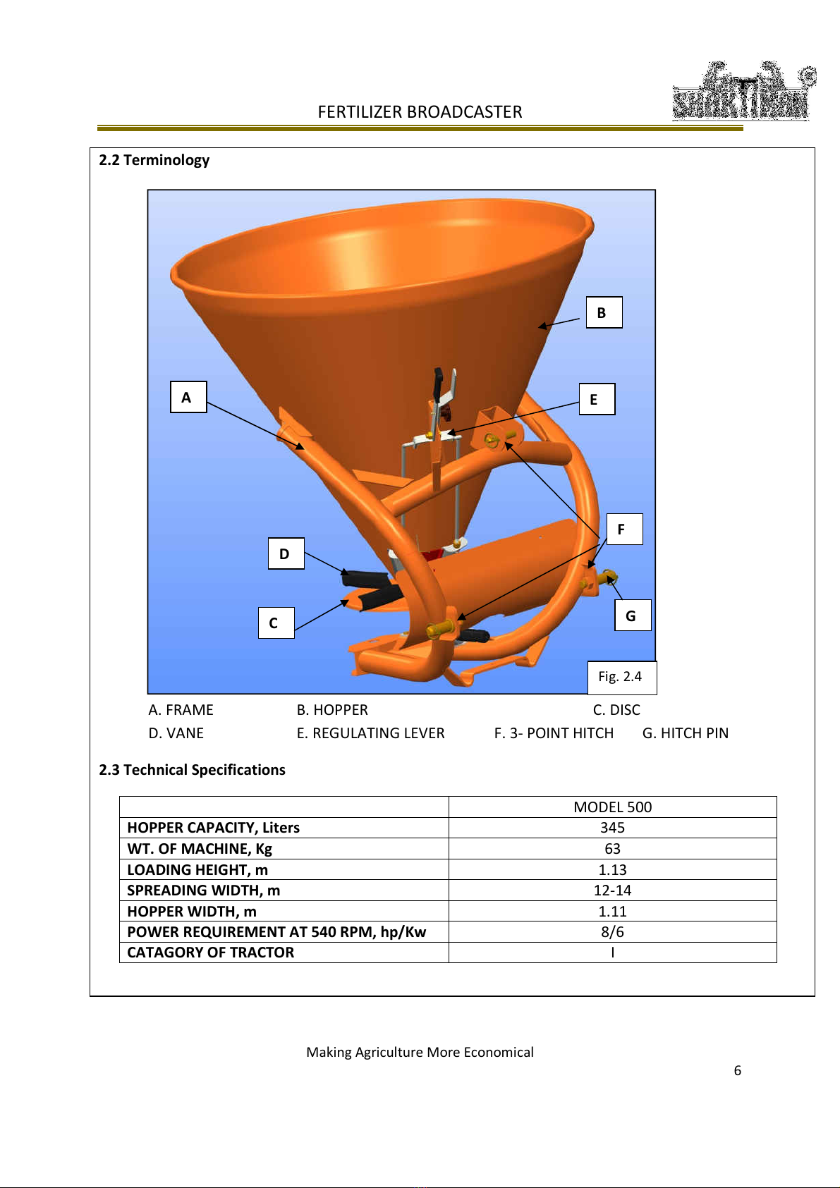
2.2 Terminology
A. FRAME B. HOPPER C. DISC
D. VANE E. REGULATING LEVER F. 3- POINT HITCH G. HITCH PIN
2.3 Technical Specifications
MODEL
500
HOPPER APA ITY, Liters 345
WT
.
OF MA HINE, Kg
63
LOADING HEIGHT, m
1.1
3
SPREADING WIDTH, m 12-14
HOPPER WIDTH, m
1.11
POWER REQUIREMENT AT 540 RPM, hp/Kw 8/6
ATAGORY OF TRA TOR
I
Fig. 2.4
A
B
D
E
F
G

03-SAFETY
3.1 Recognize Safety Information
This is a safety-alert symbol. When you see this symbol on your
machine or in this manual, Be alert to the potential for personal injury.
Follow recommended and safe operating
practices.
3.2 Understand
Signal
A signal word—DANGER, WARNING, or CAUTION—is used with the safety-
alert symbol. DANGER identifies the most serious hazards.
DANGER or WARNING safety signs are located near specific hazards. General
precautions are listed on
CAUTION safety signs. CAUTION also calls attention to safety messages in this
manual.
3.3 Follow Safety Instructions
Carefully read all safety messages in this manual and safety
signs on your machine. Keep safety signs in good condition.
Replace missing or damaged safety signs. Be sure new
equipment components and repair parts include the current
safety signs. Replacement safety signs are available from your
Shaktiman dealer.
There can be additional safety information contained on parts
and components sourced from suppliers that is not reproduced
in this operator's manual.
Learn how to operate the machine and how to use controls
properly. Do not let anyone operate without instruction.
Keep your machine in proper working condition.
Unauthorized modifications to the machine may impair the function and/or safety and affect machine life.
If you do not understand any part of this manual and need assistance, contact your Shaktiman dealer.
The manufacturer declines all and every responsibility for failure to comply with the safety and accident preventing
instructions mentioned in this manual book.

3.4 Operate Machine Safely
Thoroughly read all the instructions for safely
operation of the Machine.
•Before starting the tractor and implement, always
check all the safety devices are in perfect
conditions.
•It is absolutely prohibited for persons without a
driving license, inexpert persons or those in
precarious health conditions to drive the tractor
with implement mounted.
•The coupled implement may only be controlled
through the propeller shaft complete with
necessary safety devices for the overloads and
with the guards having the appropriate chains.
Keep away from the propeller shaft while it is
turning.
•Always take care of the centrifugal force
exercised by the furthered position of the centre
of gravity, when turning corners with the
implement mounted.
•Before engaging the PTO, check that RPM rate
that is prescribed. Never exchange the 540 RPM
rate for 1000 RPM rate.
•Before leaving the tractor, lower the implement
coupled to the lift unit, stop the engine, engage
the hand brake and remove ignition key from the
control panel.
•It is absolutely prohibited to stand between the
tractor and the implement where the engine is
running and the propeller shaft is engaged
without having first engaged the hand brake and
placed a block or stone under the wheels to
prevent them from moving.
•Always set the lift control lever to the locked
position before coupling or releasing the
implement from the three point coupling.
•The category of the implement coupling pins
must correspond to that of lift coupling.
•Take care when working near the lift links. This
is a very dangerous zone.
•It is absolutely prohibited to stand between the
tractor and the implement when maneuvering the
lift control from the outside.
•Fix the side lift links with the relative chains and
idlers during the transport phase.
•Set the control lever of the hydraulic lift to the
locked position during road transport with the
implement raised.
•Only use the propeller shaft recommended by the
manufacturer.
•Take great care of the propeller shaft guard, both
in the transport and work positions.
•The propeller shaft must only be installed or
dismantled whilst the engine is off.
•Take great care to ensure that the propeller shaft
is correctly assembled and safe, and carefully
check the PTO of the implement and the tractor.
•Before engaging the PTO, ensure that there is no
person and animal in the field of action of the
machine and that the selected running rate
corresponds to the permissible value. Never
exceed the recommended maximum rate.
•Never engage the PTO when the engine is off.
•Only clean and grease the propeller shaft when
the PTO is disengage, the engine is off, the hand
brake engaged and the ignition key removed.
•Refit the protective cap on the input shaft after
having dismantled the propeller shaft.
•Never carry out maintenance or cleaning work
unless the PTO has been disengaged, the engine
switched off and the hand brake engaged and the
tractor locked in position by a block or stone
under the wheels.
•Always place adequate supports under the
implement when servicing the machine
•Before working on vanes, disengage the PTO,
switch off the tractor engine, engage the hand
brake and check all the blades are completely at
a standstill.
•Operate the implement carefully to avoid injury.
If the implement must be raised for work on or
near the implement make sure the service locks
are installed or that the implement is safely
supported.
•Be careful when operating the implement on
slopes; the tractor can overturn if it hits a hole or
ditch or if it encounters rough terrain.
•Only one person, the operator, should be in the
tractor operator’s station when the tractor and the
implement are in use.
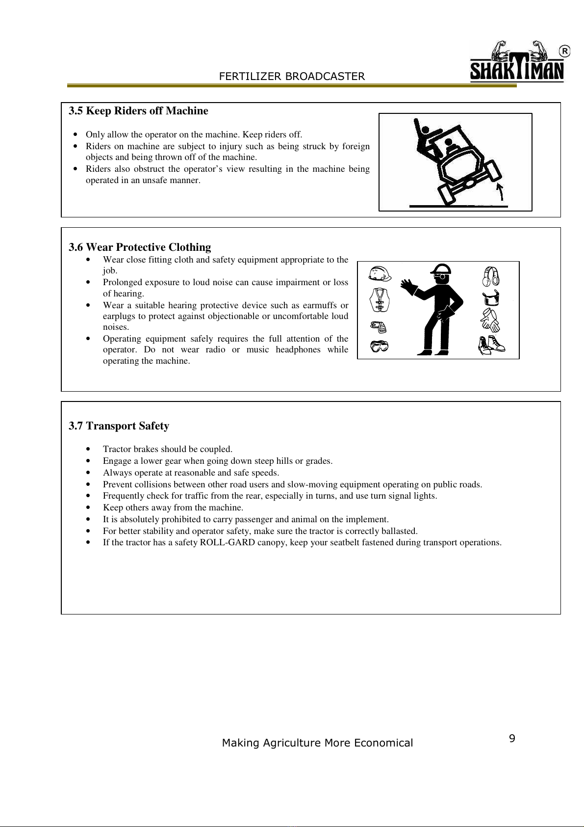
3.5 Keep Riders off Machine
•Only allow the operator on the machine. Keep riders off.
•Riders on machine are subject to injury such as being struck by foreign
objects and being thrown off of the machine.
•Riders also obstruct the operator’s view resulting in the machine being
operated in an unsafe manner.
3.6 Wear Protective Clothing
•Wear close fitting cloth and safety equipment appropriate to the
job.
•Prolonged exposure to loud noise can cause impairment or loss
of hearing.
•Wear a suitable hearing protective device such as earmuffs or
earplugs to protect against objectionable or uncomfortable loud
noises.
•Operating equipment safely requires the full attention of the
operator. Do not wear radio or music headphones while
operating the machine.
3.7 Transport Safety
•Tractor brakes should be coupled.
•Engage a lower gear when going down steep hills or grades.
•Always operate at reasonable and safe speeds.
•Prevent collisions between other road users and slow-moving equipment operating on public roads.
•Frequently check for traffic from the rear, especially in turns, and use turn signal lights.
•Keep others away from the machine.
•It is absolutely prohibited to carry passenger and animal on the implement.
•For better stability and operator safety, make sure the tractor is correctly ballasted.
•If the tractor has a safety ROLL-GARD canopy, keep your seatbelt fastened during transport operations.

!
3.8 Comply with the Transport Speed Limit
The maximum permissible travel speed for this implement is 20 km/h (12 mph).
Some tractors can operate at speeds higher than the maximum speed limit for this implement. Do not exceed the
implement's transport speed limit.
Exceeding the implement's maximum transport speed can result in:
• Loss of control of the tractor/implement combination
• Reduced stopping power or no ability to stop during braking
• Damage to the implement's structure or components
Be careful and slow down in adverse conditions, when turning and when operating on slopes.
3.9 Service Machine Safely
•To help prevent personal injury caused by unexpected movement, be sure to service machine on level
surface.
•If the implement must be in a raised position while working on or near it, be certain service locks are
installed or machine is adequately supported.
•If implement is connected to tractor, engage parking brake and/or place transmission in “PARK”, shut off
engine and remove key.
•If the implement is detached from tractor, block wheels and use safety stands to prevent movement.
•Operations and adjustments to the implement must always be carried out when the engine is off and tractor
braked.
3.10 Practice Safe Maintenance
•Understand service procedure before doing work. Keep area clean and dry.
•Never lubricate, service, or adjust implement while it is moving. Keep hands, feet, and clothing from
power-driven parts. Disengage all power source. Lower implement to the ground. Stop the engine. Remove
the key. Allow implement to cool.
•Securely support any implement elements that must be raised for service work.
•Keep all parts in good condition and properly installed.
•Fix damage immediately. Replace worn or broken parts.
•Remove any buildup of grease, oil, or debris.
04-SAFETY SIGNS
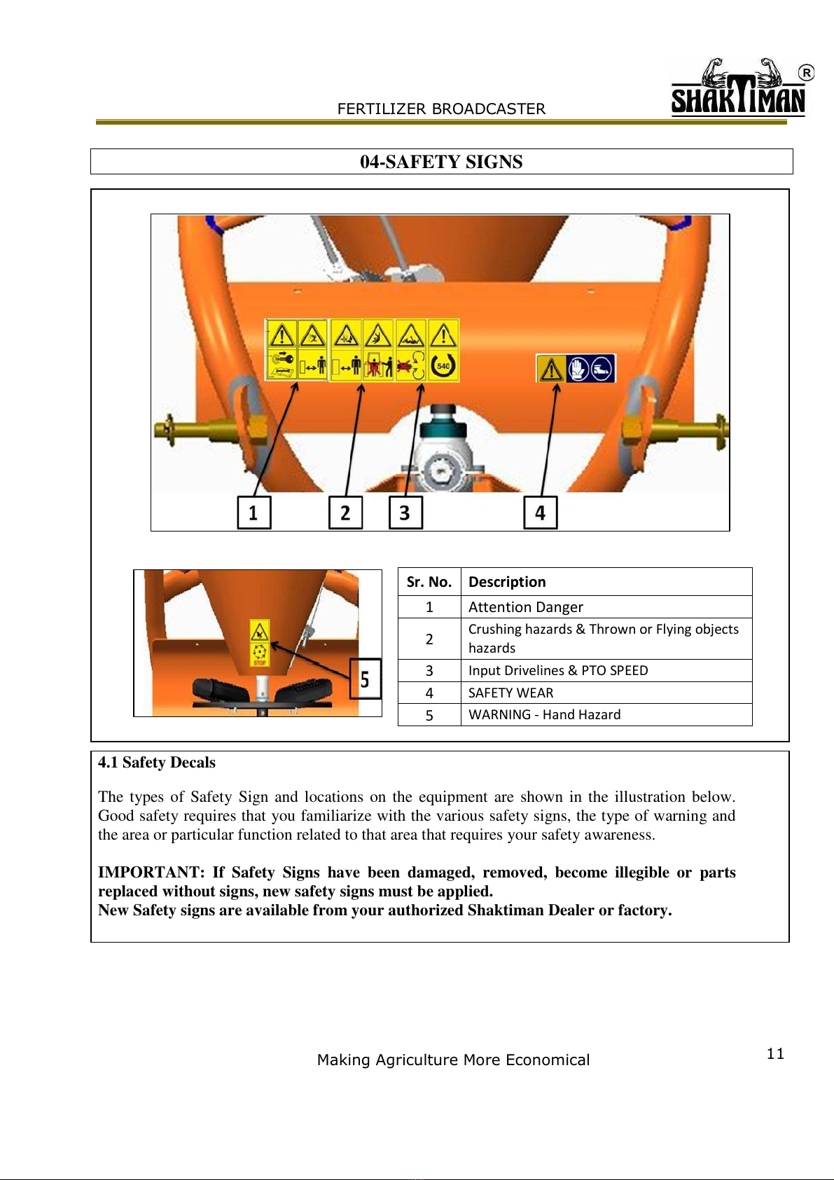
4.1 Safety Decals
The types of Safety Sign and locations on the equipment are shown in the illustration below.
Good safety requires that you familiarize with the various safety signs, the type of warning and
the area or particular function related to that area that requires your safety awareness.
IMPORTANT: If Safety Signs have been damaged, removed, become illegible or parts
replaced without signs, new safety signs must be applied.
New Safety signs are available from your authorized Shaktiman Dealer or factory.
Sr. No. Description
1 Attention Danger
2
Crushing hazards & Thrown or Flying objects
hazards
3
Input Dri elines & PTO SPEED
4
SAFETY WEAR
5
WARNING - Hand Hazard

Sr. No.
Decal No. Description Picture
1
Attention Danger
•Before making any operation on the machine, stop the
engine of the tractor or the self moving means,
remove the key, put on the parking brake and read
carefully the operator’s manual.
•Attention danger possible throwing of material and/or
objects, please do not come up the machine.
•
Keep a safety distance of 50 meters, at least, from the
machine.
2 !
Crushing hazards & Thrown or flying objects hazards
•Attention danger of crushing.
•Do not stand between the machine and tractor when
the tractor engine is running.
3 !
Input Drivelines & PTO SPEED
•Attention checks the sense of rotation and the number
of revolutions (540 rpm) of the tractor power placing
the PTO shaft.
•Attention danger of entangling and dragging. Do not
put hands near the running gearbox.
4 "!
SAFETY WEAR
•
Attentions use the individual protection devices, as
required.

#
5 !
WARNING Hand Hazard
•Wait until all machine components have
completely stopped before touching them.

05-PREPARING THE TRACTOR
5.1 Use Your Tractor Operator's Manual
Note: Use the proper HP of tractor for the particular model of machine. See the section
technical specification
•Always refer to YOUR tractor operator's manual for specific detailed information regarding
operation of YOUR equipment.
•Following tractor related information uses tractors to illustrate preparation, attachment and
operational procedures.
•Use your tractor OM for detailed information.
5.2 Front Counterweight
CAUTION: The front counterweight may not be able to maintain tractor stability if the
tractor is driven at excessive speed on rough ground with the implement raised. Drive
slowly and carefully in these conditions.
A minimum of 20 % of tractor and implement weight must be on the tractor front wheels.
Install the appropriate amount of weight on the tractor front end. The weight may be
attained with a front wheels weight, ballast in the tires or front tractor weight. For more
detail see the tractor operator manual.

06-PREPARING THE IMPLEMENT
•Tighten all bolts and nuts. See the bolt torque tables in the maintenance section.
•Before starting the implement check that the machine is perfectly in order, that the
lubricants are at the correct level and all parts subjected to wear and deterioration are
fully efficient.
•6.1 Upper Agitator Assembly :
IMPORTANT
:Agitator should only be used with light fluffy material such as grass
seeds, powdered fertilizer etc. Do not use with heavy dense materials such as fertilizer,
salt and sand. Doing so can break the agitator.
•Check buffer wheel (2 in Fig. 6-1) to make sure it spins freely on the agitator. Slightly
loosen nylock nut M12 (4 in Fig. 6-1) if buffer wheel does not spin freely.
•Attach upper agitator (1 in Fig 6-1) with entainer with M12 X 1.75 X 55 hex bolt (5 in Fig.
6-1). Secure with nylock nut M12 (4 in Fig. 6-1). Draw locknut up snug. Do not tighten.
Fig. 6-1
07-ATTACHING AND DETACHING THE IMPLEMENT
7.1 Use Your Tractor Operator's Manual
•Always refer to YOUR tractor operator's manual for specific detailed information regarding
operation of YOUR equipment.
•Following tractor related information uses tractors to illustrate preparation, attachment and
operational procedures.
•Use your tractor OM for detailed information, as procedures will vary by equipment
7.2 Attaching implement to the Tractor
Implement can be attached to the suitable category tractor.
Follow below procedure for attaching the implement to the tractor
Warning: Trained person is required to attach and detach from the tractor. Else may
cause major injury to operator and sevier damage to equipment and tractor.
Caution: Implement should always be park on level ground for attaching an detaching to
tractor safely and easily.
Caution: Before attaching equipment to the tractor, check for any accessories fitted on
tractor like drawbar, swinging drawbar, automatic hitch etc for any hindrance, restriction,
proper functioning and free up and movement of equipment. If required remove accessories
before attaching equipment.
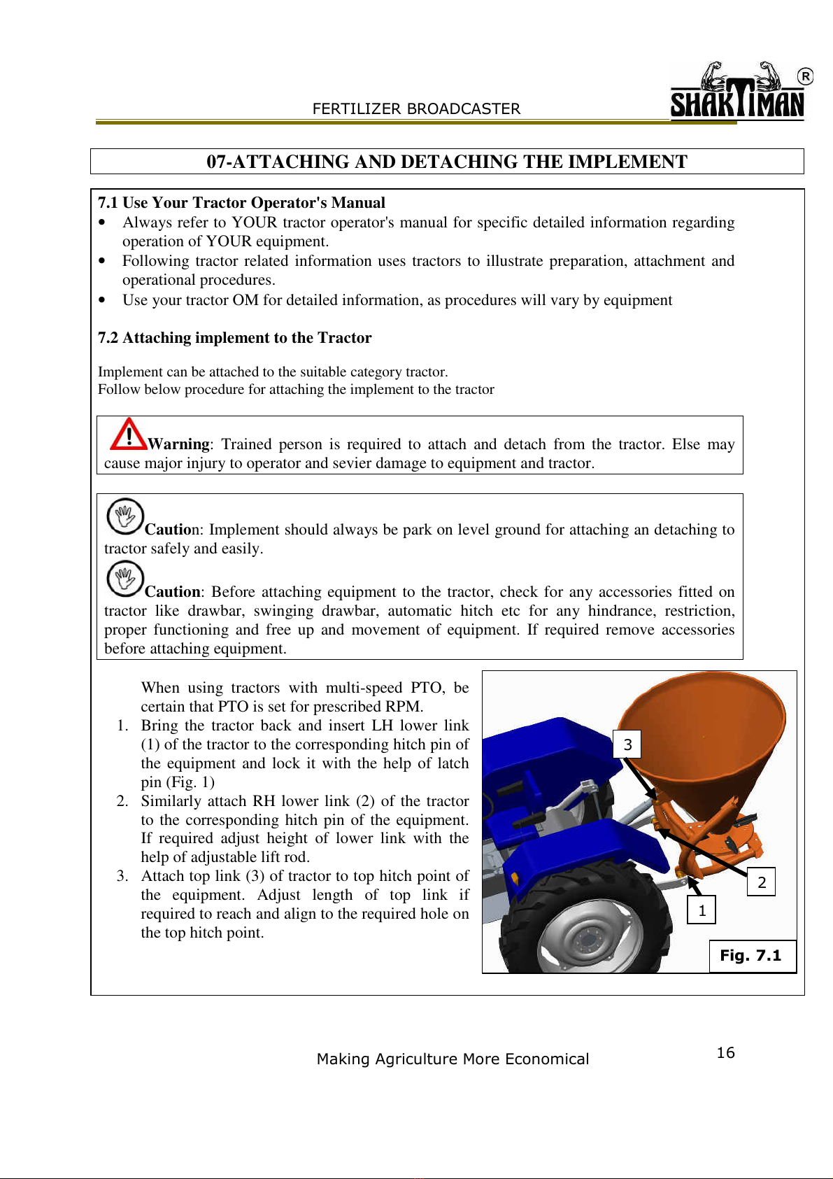
When using tractors with multi-speed PTO, be
certain that PTO is set for prescribed RPM.
1. Bring the tractor back and insert LH lower link
(1) of the tractor to the corresponding hitch pin of
the equipment and lock it with the help of latch
pin (Fig. 1)
2. Similarly attach RH lower link (2) of the tractor
to the corresponding hitch pin of the equipment.
If required adjust height of lower link with the
help of adjustable lift rod.
3. Attach top link (3) of tractor to top hitch point of
the equipment. Adjust length of top link if
required to reach and align to the required hole on
the top hitch point.

!
7.3 Universal Propeller shaft Attachment
Warning: Length of propeller shaft is very important and requirement may vary from
tractor to tractor. Please read section Universal propeller shaft length adjustment.
During propeller shaft installation, push the pushpin (1) then
slide one end of propeller shaft over the tractor’s splined
PTO shaft and secure with locking device(push pin) 1 of
drive shaft. Do the same process for the other end of the
Propeller shaft.
Propeller shaft now be moved back and forth to ensure that
it is secure on the PTO shaft of the tractor and implement
gearbox.
Note: The till of the universal propeller shaft must
not exceed 35
o
. (Fig. 5)
7.4 Detaching Implement from the Tractor
•Detaching the equipment from tractor is reverse
procedure of attaching the equipment.
•First lift down the equipment on the level ground
and lower the stand and lock the stand so that equipment should not erect after detaching
from tractor.
•Remove propeller shaft, followed by top link, then LH lower link and RH lower link of
tractor.
7.5 Universal Propeller Shaft Length Adjustment
IMPORTANT:
•The propeller shaft which will be used to operate the machine must definitely have
protective covers.
•Propeller shaft without protective covers should never be used.
•The tractor may not be running during the mounting and dismounting of the shaft.
•No other persons should be around the propeller shaft during processes with the shaft.
Attention: The universal propeller shaft supplied, with the machine, is of standard length.
Therefore it might be necessary to adapt the universal drive shaft.
Make sure the PTO shaft length is compatible with the different working positions of the
implement. If the PTO shaft is too long it might bend and damage may occur to the tractor or
implement.

"
Place the tractor and the implement on a flat surface
Attach the 3 point linkage of the tractor (see the section attaching and detaching the implement)
Find the length between the grove of PTO output on the tractor, and the PTO input on the
implement when the implement and tractor is in horizontal position.
Raise the implement fully and measure from end-
to-end between the two groves. It is used to
determine the shortest distance.
Lower the lift to about half and re-measure the
distance, then drop the lift to the bottom and re-
measure again.
Let the shortest distance be A and the longest
distance be B. (Fig. 7.4)
Put the both halves of the propeller shaft on a flat
surface parallel to each other (Fig. 7.6) in such a
way that the distance between the two push pin (1)
of the yoke should be equal to the shortest
distance A.
Measure the minimum clearance, this distance should be minimum 4 cm (Fig. 7.6), if this
distance is more than 4 cm then no need to cut the shaft. If the clearance is less than 4 cm then
cut the pipe of propeller shaft along with cover both side such that the minimum clearance of 4
cm is maintained.
Again, put the both halves of the propeller shaft on a flat surface parallel to each other (Fig. 7.5)
in such a way that the distance between the push pin (1) of the yoke should be equal to the
maximum distance B. If the minimum overlap is 15 cm then no need to resize the propeller shaft
and it is ready to be fit the tractor with the implement.
Danger: failure to make these adjustments will damage the unit and causes personal injury.
Note: Clean the filings from the metal and dress the edges of the cuts with a file when
done.
#
08-TRANSPORTING
8.1 Transport Safely
CAUTION: When transporting on a public road or highway, use accessory lights and
devices to provide adequate warning to operators of other vehicles.
Contact with electrical cables can cause severe injury or death. When transporting or
operating the machine, make sure to avoid contact with electrical lines.
When transporting the implement, always travel at a speed that allows adequate control of
steering and stopping.
CAUTION: When transporting the implement on a smooth surface road, do not
operate the tractor at more than 20 km/h (12 mph). Reduce speed considerably when
traveling over uneven ground. Make sure there is no one near the implement.
In the transport position, be sure to determine the amount of implement travel behind the tractor
when turning corners. Be aware of width and height limits to avoid collisions with bridges and
other vehicles.
Comply with the following recommendations:
•Use tractor with sufficient capacity to maintain control. Install adequate ballast on the tractor.
•Couple tractor brake pedals together.
•If the tractor has a safety ROLL-GARD canopy, keep your seatbelt fastened during transport
operations.
•Engage a lower gear when going down steep hills or grades; never coast down hills.
•Always use the warning lights, day and night, when operating on public roads. Keep the
reflectors clean and visible.
•Prevent collisions between other road users and slow-moving equipment operating on public
roads.
•Frequently check for traffic from the rear, especially in turns, and use turn signal lights.
•Stopping distance increases with the speed and weight of mounted loads, and on slopes.
Observe these recommended maximum travel speeds or the local speed limit that might be
lower. Do not go faster than 20 km/h (12 mph).
•Ensure that the load does not exceed the recommended weight distribution. Add ballast while
complying with tractor limits, lighten the load or use a heavier tractor.
•Be especially careful when transporting the machine in adverse conditions, when turning and
when operating on slopes.
Table of contents


