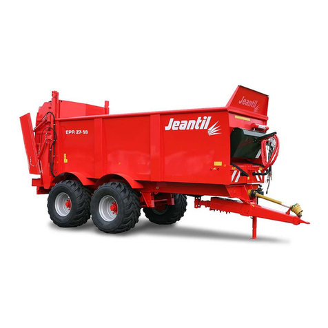
JEANTIL EVR 8-6 User manual

1
INSTRUCTION MANUAL
11/2007
PLEASE READ CAREFULLY AND UNDERSTAND BEFORE USING THE
EQUIPMENT
SPREADER WITH VERTICAL BEATERS
JEANTIL
Rue de la Tertrais
ZI La Hautière BP1
35590 L’HERMITAGE France
Tel : 00 33 (0)2.99.64.04.04
Fax : 00 33 (0)2.99.64.19.56
Spare parts shop tel: 00 33 (0)2.99.64.04.02
Spare parts shop fax: 00 33 (0)2.99.64.09.36
E-mail: jeantil@jeantil.com – Web site: www.jeantil.com
EVR 8-6
EVR 10-6
EVR 12-8
EVR 13-10
EVR 15-12
EVR 14-11
EVR 14-12
EVR 16-12
EVR 16-12 T
EVR 18-14
EVR 18-14 T
EVR 21-15
540revs/min
1000revs/
min
N°10

2
1. Aim of the Instruction Manual
a) General
The manual concerns all users of the equipment and any person responsible for
assembling, installing, operating, adjusting, servicing, repairing or transporting
the equipment and its accessories.
The manual contains practical information for the correct and safe operation,
handling, adjusting and maintenance of your equipment.
Read carefully and ensure you understand the content before using the
equipment. Comply with the instructions and the safety-related advice.
b) Warning symbols
This warning symbol identifies important advice that must be followed for
your safety. When you see this symbol, be aware that there is a potential risk of injury;
read carefully the advice that follows it and inform other users.
c) Keeping the manual
Always keep this manual within easy reach or at your place of work (or
operating site).
Pass it on to any other user, including if you lend or sell the equipment.
d) Contact details (customer service)
JEANTIL
Rue de la Tertrais
ZI de La Hautière
35590 L’HERMITAGE – France
Tel : 00.33. (0)2.99.64.04.04
Fax : 00.33. (0)2.99.64.19.56
Spare parts shop tel: 00.33. (0)2.99.64.04.02
Spare parts shop fax: 00 33 (0)2.99.64.09.36
e) Statement of compliance with the European ‘Equipment’ directive N°98/37/CE
And to any relevant transposition regulations

3
The manufacturer: JEANTIL
Rue de la Tertrais
ZI de La Hautière
35590 L’HERMITAGE – France
DECLARES THAT THE EQUIPMENT manufactured by JEANTIL as designated
below:
EVR 8-6 EVR 10-6 EVR 12-8 EVR 13-10 EVR 15-12 EVR 14-11
EVR 14-12 EVR 16-12 EVR 16-12T EVR 18-14 EVR 18-14T EVR 21-15
SERIAL N°: ……………
COMPLIES WITH:
1. Labour regulations
2. The revised European equipment directive N°98/37/EC
3. Revised EMC directive (electromagnetic compatibility) N° 89/336 EC
4. Specific safety standards: NF / En 690 (Spreaders)
5. General safety standards: NF/EN/ISO 12100-1
NF/EN/ISO 12100-2
NF/EN 294
NF/EN 349
NF U 02-001-ISO 4254/1
NF EN 1553
NF EN 811
6. Highway code
SIGNED AT L’HERMITAGE (DATE)
NAME OF SIGNATORY: JEANTIL Philippe

4
2. Contents
1. Aim of the instruction manual p.2
a. General p.2
b. Warning symbols p.2
c. Keepingthemanual p.2
d. Contact details (customer service) p.2
e. Statement of compliance with the European ‘equipment’ directive p.3
2. Contents p.4
3. Equipment identification p.6
4. Standard operating conditions p.7
a. Applications of the equipment p.7
b. Operator qualification p.7
c. Defining the operating stations p.7
d. Environmental conditions p.7
e. Manufacturer’s and user’s responsibilities p.8
5. Technical characteristics p.8
1- Dimensions p.8
2- Stowing diagram p.10
6. General safety rules p.11
1) General p.11
2) Warning / Pictograms p.12
3) Coupling p.14
4) PTO / Drive shaft p.14
5) Failure (or jamming of the equipment) p.15
6) Maintenance and repair p.15
6. a / General p.15
6. b / Welding operations p.16
6. c / Servicing the tyres p.16
6. d / Electric servicing p.16
6. e / Hydraulic servicing p.16
6. f / Repair p.16
7. Environmental protection p.17
8. Fitting and installation p.17
1- Coupling p.17
2- Drive shaft p.18
3- Hydraulics p.18
4- Electricity p.19

5
9. Adjustments and maintenance p.20
1 – Greasing p.20
2 – Reduction gear p.21
3 - Chains p.21
4 - Wheels p.22
5 – Hydraulic hoses p.22
6 – Hydraulic safety valve p.23
7 –Safety valve of hydraulic door p.23
8 –Tail lights for road signalling p.23
9 – Speed of moving floor’s hydraulic motor p.24
10 – Torque limiter with two adjustable and declutchable cams p.24
(Secondary EPAN 5) WALTERSCHEID
11 – Torque limiter with 1 shear bolt, Secondary EVR 8-6 EPAN 5 WALTER. p.26
12 – Torque limiter with side cams EPAN 6 WALTERSCHEID p.26
13 – Assembling the beater fingers and small kits / DLG p.27
10. Start-up and operation p.27
11.Uses p.27
1 – Spreading quantity per hectare p.27
2 – Loading p.28
3 – Spreading p.29
4 – When the spreading is finished p.30
12. Additional equipment information p.30
1– Independent hydraulic power unit (Price ref 2236) p.30
2 –Spreader meter (Price ref 2155) p.31
3 –Rear door for thick slurry (Price ref 2860 / 2862) p.31
4– Single-acting hydraulic stand (Price ref 2147) N° 822007 p.32
5 –Dual-acting hydraulic stand (Price ref 2147) N° 891 008 p.32
6– Spreading device EPAN 6 (Price ref 2837) p.32
7 – Hydraulic divider for tractor flow rates exceeding 45l / min (Price ref 8958) p.34
13. Cleaning p.34
14. List of technical documents p.35
I. Supplier spare parts p.35
II. JEANTIL spare parts p.37
III. Other p.37
14. Possible incidents and solutions p.38

6
3. Equipment identification
Type
N° de
série
Année de
construction
P.T.A.C.
Réceptionné
Masses
maximales
admissibles
Anneau
Essieu 1
Essieu 2
kg
kg
kg
kg
20
kg
Essieu 3
35590 L'HERMITAGE - FRANCE
Ref: 892 770
Manufacturer’s plate to EC standards.
Never remove the manufacturer’s plate and the EC marking fixed
to the equipment.

7
4. Standard operating conditions
a) Applications of the equipment:
1. This equipment is intended exclusively for general agricultural purposes i.e.:
Transporting and spreading products such as: bovine manure, thick mud and slurry, lime
and compost.
2. Any other use falls outside normal usage and is therefore forbidden.
3. For any other use, please contact the manufacturer.
b) Operator qualification:
1. The equipment must only be used, maintained and repaired by trained operators; see
page 2 “Aim of the Instruction Manual”.
2. Before using your equipment, acquaint yourself with all controls and their correct
operation.
3. All users, prior to using the spreader, must have carefully read this Manual, have
understood it and applied all the safety instructions. Once working, it will be too late to
do this.
c) Defining the operating stations:
1. The only operating station for the equipment is the tractor’s driving station.
2. Never leave the driving station when the engine of the tractor and the equipment are
operating.
3. To access the operating station, use the access devices provided by the manufacturer
(ladder, running board).
d) Environmental conditions
1. Never approach or remain in the areas that are dangerous when the equipment is in
operation.
2. Adapt your speed and driving style to the lands, roads and tracks. Be cautious and
careful!
3. Do not operate vehicles on slopes (tilting backwards, forwards or on the side) when
there is a risk of tipping or overturning.
4. Do not start or brake abruptly.
5. Operate your equipment with sufficient light to ensure safety; use appropriate artificial
light if necessary (contact your dealer or mechanic).

8
e) Manufacturer’s and user’s responsibilities
1. Follow all advice contained in this manual regarding levels of knowledge, installation
procedures, operation, adjustment, maintenance and repair.
2. Only use spare parts and accessories that comply with the manufacturer’s
recommendations.
3. Do not carry out any modifications yourself and do not allow others to modify your
equipment and its accessories (mechanical, electrical, hydraulic or pneumatic
characteristics) without requesting prior written approval from the manufacturer.
4. Failure to comply with these requirements may make the machinery dangerous. The
manufacturer disclaims any responsibility if damage or injury arises from such action.
5. Technical characteristics
1 Dimensions:

9
TYPES EVR
8.6 EVR
10.6 EVR
12.8 EVR
13.10 EVR
15.12 EVR
14.11 EVR
14.12 EVR
16.12 EVR
16.12 T EVR
18-14 EVR
18-14 T EVR
21-15
Manure volume 8 m³ 10.5 m³ 11.5 m³ 12.8 m³ 14.5 m³ 14.5 m³ 14.5 m³ 16 m³ 16 m³ 17.6 m³ 17.6 m³ 20.6 m³
Working load 6 t 6 t 8 t 10 t 12 t 11 t 12 t 12 t 12 t 14 t 14 t 15 t
Road working load
(standard equipment without
options) 4.2 t 4.3 t 7.51 t 7.34 t 7.30 t 7.10 t 7.10 t 8.22 t 12 t 10.06 t 14 t 15 t
A : Internal length of body 4,20 m 4,20 m 4,65 m 5,15 m 5,65 m 5.15 m 5.15 m 5.65 m 5.65 m 6,25 m 6,25 m 7,25 m
B : Internal width of body 1.50 m 1.50 m 1.50 m 1.50 m 1.50 m 1.50 m 1.50 m 1.50 m 1.50 m 1.50 m 1.50 m 1.50 m
C : Internal width of body upper
part 1.85 m 2.00 m 2.00 m 2.00 m 2.00 m 2.00 m 2.00 m 2.00 m 2.00 m 2.00 m 2.00 m 2.00 m
D : Internal height of body 1.00 m 1.20 m 1.20 m 1.20 m 1.20 m 1.40 m 1.40 m 1.40 m 1.40 m 1.40 m 1.40 m 1.40 m
E : Overall length 6.40 m 6.40 m 6.85 m 7.35 m 7.85 m 7.35 m 7.35 m 7.85 m 7.85 m 8.45 m 8.45 m 9.45 m
F : Overall width 2.55 m 2.55 m 2.55 m 2.55 m 2.55 m 2.55 m 2.55 m 2.70 m 3.00 m 2.85 m 3.00 m 3.00 m
G : Beater length 1.60 m 1.80 m 1.80 m 1.80 m 1.80 m 2.00 m 2.00 m 2.00 m 2.00 m 2.00 m 2.00 m 2.00 m
H : Height under frame 1.30 m 1.50 m 1.50 m 1.50 m 1.50 m 1.70 m 1.70 m 1.70 m 1.70 m 1.70 m 1.70 m 1.70 m
I : Overall height
(with standard wheels and
equipment) 2.75 m 2.75 m 2.80 m 2.80 m 2.85 m 3.00 m 3.05 m 3.05 m 3.08 m 3.04 m 3.08 m 3.13 m
J : Loading height
(with standard wheels and
equipment) 2.15 m 2.35 m 2.40 m 2.40 m 2.45 m 2.62 m 2.67 m 2.67 m 2.70 m 2.66 m 2.70 m 2.75 m
K : Overall height
(with guillotine door) 2.90 m 2.90 m 2.95 m 2.95 m 3.00 m 3.15 m 3.20 m 3.20 m 3.23 m 3.19 m 3.23 m 3.28 m
The equipment complies with safety standards. We reserve the right to change our
equipment and their characteristics at any time.

10
2 Stowing diagram:

11
6. General safety rules
1) General
1. Never forget that knowledge, awareness and caution are the best way to ensure your
safety.
2. Regulations and rules relating to accident prevention, health and safety at work, and the
operation of vehicles on the public highway must be observed at all times.
3. Chapter 4 (Standard operating conditions) of this Instruction Manual, contains basic
directives that must be followed for the sake of your safety.
4. Make sure that no person, animal or obstruction is located near the equipment before it
is set in motion and throughout its operation or any other manoeuvre.
5. Children must never be allowed near the equipment.
6. Never carry passengers on the equipment.
7. Do not step on the hoods or on any other parts of the equipment, except areas provided
for this purpose (ladder, platform, and means of access to the work station).
8. Before carrying out any work on the equipment, ensure that it cannot be started up
accidentally.
9. All controls (ropes, cables, rods, hoses, etc.) must be positioned in the locations
provided for them so that they cannot accidentally initiate a manoeuvre likely to cause
an accident or damage.
10. Before use and after any adjustment or maintenance, ensure that all protective devices
are in position and in good condition, and that their latches are engaged.
11. Before use, check tightness of screws, nuts, connectors and wheels. Retighten if
required.
12. Do not wear loose clothing, long untidy hair and jewellery that might get caught in the
moving parts of the equipment.
13. Keep your hands, arms and feet well away from any moving parts, even those that are
slow-moving. Keep well away from moving parts.
14. If you detect any unusual noise or vibration, stop the equipment, and identify and
eliminate the cause of the incident before resuming work. Contact your dealer if
required.

12
2) Warning / Pictograms
1. Warnings and pictograms placed on the equipment provide information about safety
measures to be taken, that will contribute to avoid accidents.
2. Make sure that these warnings and pictograms remain clean and legible. If they are
damaged, ask for new stickers from the manufacturer (or agent).
3. If repairs are carried out, check that the replacement parts carry the same stickers as
those that have been removed.
Ref: 892 640
SAFETY AND OPERATING STICKER
CLEARLY placed IN FULL VIEW on the
front of all items of equipment, close to the
components used to connect the unit to the
tractor.
Ref: 892 651
Placed on the left side of
the drive shaft casing
Ref: 892 653
Placed at the
back of wheel
mudguard
Ref: 892 453
Placed above
right and left
tail lights
Ref: 892 299
Placed on rear
left side, near
rear door valve

13
Stickers for use of equipment:
Ref: 892 227
Placed on the right and left sides of the
body
Ref: 892 229
Ref: 892 446
Placed on primary drive shaft
metal casing
Réf : 892 230
Placé à l’avant de l’épandeur
Ref: 892 687
Placed on the rear
right and left sides
of spreader
Ref: 892 230
Placed at the front of the spreader
Ref: 892 652
Placed next to parts
which need greasing,
See diagram
Ref: 892 677
EVR without
distributor
Réf : 892 677
EVR sans distributeur
Ref: 892 703
EVR with distributor
and rear cover
Ref: 892 677
EVR without distributor

14
3) Coupling
1. See chapter 5, Technical characteristics, page 8.
2. Hitching the machine to the tractor must only be carried out using the tractor’s rear
coupling points provided for this purpose.
3. Check the compatibility of the machine with the tractor (minimum engine power, type
of coupling, tractor PTO characteristics, etc.). Keep clear of the area between the tractor
and the machine until you have stopped the tractor’s engine and removed the starter key.
4. Keep clear of the area between the tractor and the machine during any lifting manoeuvre
of the tractor.
5. When manoeuvring, select the lowest possible tractor gear ratio. When coupling, attach
the equipment’s electric control unit in the tractor cab, ensuring that it cannot move
during operations.
6. Once the equipment has been coupled up, the hitch must be locked. Check the coupling
is correctly locked and in good condition before any movement.
7. Check that the equipment’s coupling does not create either an overload or poor weight
distribution on the tractor that might compromise stability:
- Do not exceed the maximum allowed loading for the tractor and equipment
attachment points.
- Where necessary, fit ballast weights to the mounts provided for this purpose in
accordance with the tractor manufacturer’s recommendations.
Couple the equipment to a tractor whose linkage is equipped with lateral and vertical
locking devices.
8. To drive on roads, respect the coupling height specified in the instruction manual.
4) PTO (power take-off) / Drive shaft
1. Read and learn the manufacturer’s instructions for the drive shaft, attached to the
transmission.
2. Check that the PTO guards are in place and in a good condition. Replace them
immediately if damaged.
3. Adjust the length between the tractor and the machine, retaining maximum engagement.
4. The minimum engagement length is 250mm. See white instruction stickers placed on
the front of the unit, n° 892 640 (page 12).
Before each operation, check that the drive shaft is in good condition and that it is fitted
and locked correctly.
5. Only use the drive shaft provided with the equipment or recommended by the
manufacturer.
6. Check before each use that the speed and direction of rotation of the tractor PTO are
compatible with the planned usage of the equipment.

15
5) Failure (or jamming of the equipment)
1. Stop the machine.
2. Disengage the tractor PTO.
3. Wait until all the moving parts are completely at a halt.
4. Stop the tractor engine and remove the starter key or disconnect the battery (or the
electric connector)
5. Select the gear shift into neutral.
6. Engage the parking brake.
6) Maintenance and repair
6. a / General:
1. Maintenance and repair operations must only be carried out by qualified people.
2. Always maintain the equipment and its accessories in perfect working order to
ensure safe and efficient operation.
3. Check the cleanliness of the oil.
4. Respect maintenance periods.
Before any servicing or repair:
5. Check the stability of the machine and its components.
6. Lower the equipment to the ground.
7. Fit any provided stability devices (stands, etc.).
8. Check that all moving parts are stopped.
9. Disengage the tractor PTO.
10. Disconnect the hydraulic power hoses between the tractor and the machine.
11. Stop the engine and remove the starter key, disconnect the battery (or the electric
connector).
12. Engage the handbrake.
13. Allow any component likely to be at a high temperature to cool down.
6. b / Welding operations:
1. When carrying out any welding operation on the equipment, disconnect the electric
connector and the tractor battery.

16
2. Disconnect and protect any hoses (particularly rubber) and any electric cables to
ensure that they are not damaged by incandescent particles that could cause oil loss or
a short circuit.
6. c / Servicing the tyres:
1. Only carry out work on tyres if you have the necessary specific tools and experience.
2. Incorrect fitting could seriously compromise your safety.
3. If in doubt, call in qualified staff.
4. Do not fit tyres of a different type from those recommended by the manufacturer.
5. Ensure that the tyres are inflated to the pressures recommended by the tyre
manufacturer (See sticker page 16).
6. d / Electric servicing:
Before carrying out any work on the electric system, disconnect the electric connector.
6. e / Hydraulic servicing:
1. Place all hydraulic distributors into neutral (rest).
2. Stop the tractor engine and remove the starter key.
3. Before working on the hydraulic system, check that the installation is not under
pressure.
4. Eliminate pressure before disconnecting hydraulic lines.
5. Before restoring pressure in the hydraulic lines, check that all connectors are fully
tightened and that the hydraulic hoses are in good condition and correctly protected.
6. f / Repairs:
1. Any failure that might compromise safety must be eliminated.
2. Carry out immediate repairs on any leak or failure affecting the hydraulic or electrical
systems. These must be done by qualified staff.
3. Do not attempt to find a hydraulic oil leak (under pressure) using fingers.
4. Damaged or defective protective devices or casings must be replaced immediately.
5. Any original protective device fixed to the equipment must not be removed or
modified.
6. Hydraulic hoses that originate from another hydraulic system must not be re-used.
7. When a rigid or flexible line is damaged, it must be replaced immediately.

17
8. Repairs affecting components under pressure or electrically powered require special
tools and procedures. They must only be carried out by qualified staff.
7. Environmental protection
Ground pollution:
1. Make sure that you do not spill or discard in any drainage system used lubricating oil
or other substances such as hydraulic oil…
2. Collect used fluids in sealed, clean containers designed for the purpose. Avoid using
containers used for food or drink bottles.
3. Used tyres. It is against the law to store tyres or to dump them, dispose of them in the
natural environment or burn them in the open air. Take them to a dealer or an
approved collector.
8. Fitting and installation
Hitching to the tractor
1 - COUPLING
1. See page 8 technical characteristics / and page 16 coupling.
2. Read the sticker page 12 ref: 892 640.
3. Couple the ring on the drawbar of the spreader to the attachment point or axle hook on
the rear of the tractor.
4. Check the lockings.

18
2 – DRIVE SHAFT
A/ Primary drive shaft
1. See page 14 PTO / Drive shaft
2. Read sticker page 12 ref: 892 640.
3. Read the manufacturer’s instructions concerning the drive shaft, attached to the
transmission.
4. Check the safety conditions of the guard. If it shows any sign of damage, it must be
replaced before the equipment is used.
5. The drive shaft is placed between the tractor and the spreader.
6. Fit the spreader’s primary drive shaft to the tractor’s rear PTO outlet, and adjust its
length, retaining maximum engagement. Minimum engagement length is 250 mm.
7. Ensure that both jaws have engaged correctly.
8. The primary drive shaft must be connected to the rear PTO of:
-the tractor, 540revs/min, for EVR 8-6 / 10-6 / 12-8 / 13-10 / 15-12.
-the tractor, 1000 revs/min, for EVR 14-11 / 14-12 / 16-12 / 16-12T / 18-14 / 18-14T / 21-
15.
B/ Secondary drive shaft
1. The secondary drive shaft is located between the spreader’s longitudinal main shaft
and the vertical beater drive. It is equipped with a declutchable cam limiter on the
spreaders 10-6 to 21-15 or with a shear bolt on the 8-6 near the vertical beaters, and a
freewheel on the spreader’s front side.
2. The instructions from the transmission manufacturer come with the transmission.
3 - HYDRAULICS
1. See page 16, hydraulic servicing and repairs.
2. Read sticker page 12 ref: 892 640.
3. Spreaders are designed to operate with a maximum oil flow rate of 45 l/min at a
maximum pressure of 180 bars.
4. All EVR spreaders are equipped with a simple flow regulator for the moving floor
speed (standard), or with a hydraulic distributor with an integrated flow regulator for
the moving floor speed.
5. Regulators or distributors are equipped with a pressure limiting valve set at 180 bars.
6. The distributor must be linked directly to the tractor’s pump pressure via its single-
acting distributor, with the return always routed directly and unrestrictedly to
the tractor’s oil reservoir.

19
7. The flow regulator of the moving floor should be connected to the tractor’s DUAL-
ACTING distributor. Make sure that on the end of one of the 2 hydraulic hoses there
is no check valve.
8. Avoid connecting to a dual-acting tractor distributor (pressure loss, except for point 4).
9. The hydraulic pressure hose is always located close to the pressure limiter on the
spreader’s distributor; it has a red collar. The return hose has a blue collar
10.The distributor is set at 180 bars (main valve).
11.The hydraulic braking hose, ended by a PUSH-PULL half-valve should always be
connected to the pressure outlet – tractor’s braking.
12.Tractor with flow which exceeds 45 l/min:
Provide a flow divider to be installed on the spreader, before the “PRESSURE”
orifice on the distributor unit, or contact your dealer to check whether it is possible to
adjust the tractor’s flow rate.
13.Closed circuit tractor: (Example: John DEERE)
a- To operate the equipment without the tractor having problems, activate the tractor
distributor and immediately use the equipment’s hydraulic functions.
b- As soon as the equipment’s hydraulic functions have been used, return the tractor’s
distributor to NEUTRAL.
c- For earlier models of John Deere tractors (prior to the 6000 series), check that the
tractor’s hydraulic system is not vibrating and that the equipment’s return hose is
connected to the tractor’s filter bowl; this is to avoid CAVITATION and pump
unpriming (if you experience problems, contact your John Deere dealer).
4 – ELECTRICITY
1. See page 15 and 16 section 6: Maintenance and repair.
2. Read sticker page 12 ref: 892 640.
All types of equipment (direct control from tractor or distributor) require electrical
power:
- Connection is made to the battery from a direct electrical line.
-Voltage: 12 volts DC
- Two conductors: 2.5 mm² the brown wire should be connected to battery +, and
the blue wire to battery -.
3. Signalling:
The spreaders are equipped with rear signal lights, which comply with the French
Highway Code with standard 7-contact connectors, type 12 N Normal, ISO standard
1724 N° NF 43.407, which should be connected to the socket at the back of the
tractor.

20
9. Adjustments and maintenance
1 - GREASING
1. Whilst using the equipment, grease every day.
2. The various greasing points are arranged as follows:
1- Drawbar pin (2)
2- Front shaft of moving floor, left and right side (1 Left + 1 Right)
3- Upper bearings of spreading device (1 Left + 1Right)
4- Rear shaft of moving floor, left and right side (1 Left + 1Right)
3. Regularly oil hinges and pins which are not fitted with greasers.
GREASING DIAGRAM:
This manual suits for next models
10
Table of contents
Other JEANTIL Spreader manuals
Popular Spreader manuals by other brands

Earth Way
Earth Way EV-N-SPRED 2150 Assembly and operating instructions

OEM Tools
OEM Tools 26679 Operating instructions and parts manual

TMG
TMG TMG-MSS10 product manual

Cirus Controls
Cirus Controls SpreadSmart Rx Operation manual
EINHELL
EINHELL GC-SR 12 operating instructions

Jula
Jula 709-066 operating instructions
