Shark TGB Blade 600 LTX User manual

INSTALLATION GUIDE
Protective skid plate
TGB Blade 600 LTX
ver. 04.04.2022
Full protection and ultra-light protection of your quad bottom, made of high quality
HrdPE material, equipped with water and mud holes drainage.
HrdPE cover characterizes good impact and deformation resistance.
Enjoy using it!

PROTECTIVE PLATE TGB BLADE 600 LTX
The set of protective plates is made of a specially designed material. The protective plate, after taking even a large impact
force, accumulates them and does not deform the material, returning to its original form. High quality and repeatability
of production using the latest CNC technologies ensure ease and speed of assembly. Each plate is precisely adapted to
a given quad model at the design stage, which guarantees the exact t of the elements to the structure. The kit includes
all the necessary elements, there is no need for additional modications or drilling. Read the instructions before starting
the assembly. The assembly instructions are for the TGB Blade 600 LTX model only and cannot be used with other quad
models. The surface of the material is easy to clean. Another advantage is easy access to changing uids without the need
to disassemble the plates. It is very light compared to other record makers.
INSTALLATION KIT
It contains a set of protective plates with mounting elements (screws, mounting plates, washers, sleeves, nuts and additional
fastening elements) each of the plates has its own individual installation kit, packed in separate bags for each of the plates.
It is recommended to unpack the installation elements only for the currently installed plates, which will avoid mistakes
and mixing of the xing elements. Re-sorting can be done according to with a list of mounting items attached.
TOOLS REQUIRED FOR ASSEMBLY
Allen key No. 4 (for M6 screws) and 5 (for M8)
DIRECTIONS
Screw the bolts fastening the plates to the structure elements, which will enable their position to be adjusted, and then tighten
them sensitively, without breaking the thread. After driving a dozen or so kilometers, check whether the mounting screws have
been properly tightened, any loose ones must be tightened, also with feeling :-)
The gure shows the orientation of the taps, bottom view. To properly connect the protection plates to the frame structure, the catches should settle from the top of the structural tubes,
this applies to all connections of this type specied in the diagram. The hooks and pipes are marked in red along with their orientation.
Sucient space for hands and tools allows the mounting of catches of the control arm covers at the marked points, without disassembling any other components.
Front control arm. EXAMPLE OF
MOUNTING
(Fig. 1)
Rear transverse control arm.
EXAMPLE OF MOUNTING
(Fig. 2)

INSTALLATION
The easiest way to mount it is in a tilted position on the rear part of the quad bike.
ATTENTION: CAREFULLY SECURE ALL FASTENERS TO ENSURE SAFETY
The manual provides a view of the placement of elements helping to localize fasteners and the use of individual connecting
elements.
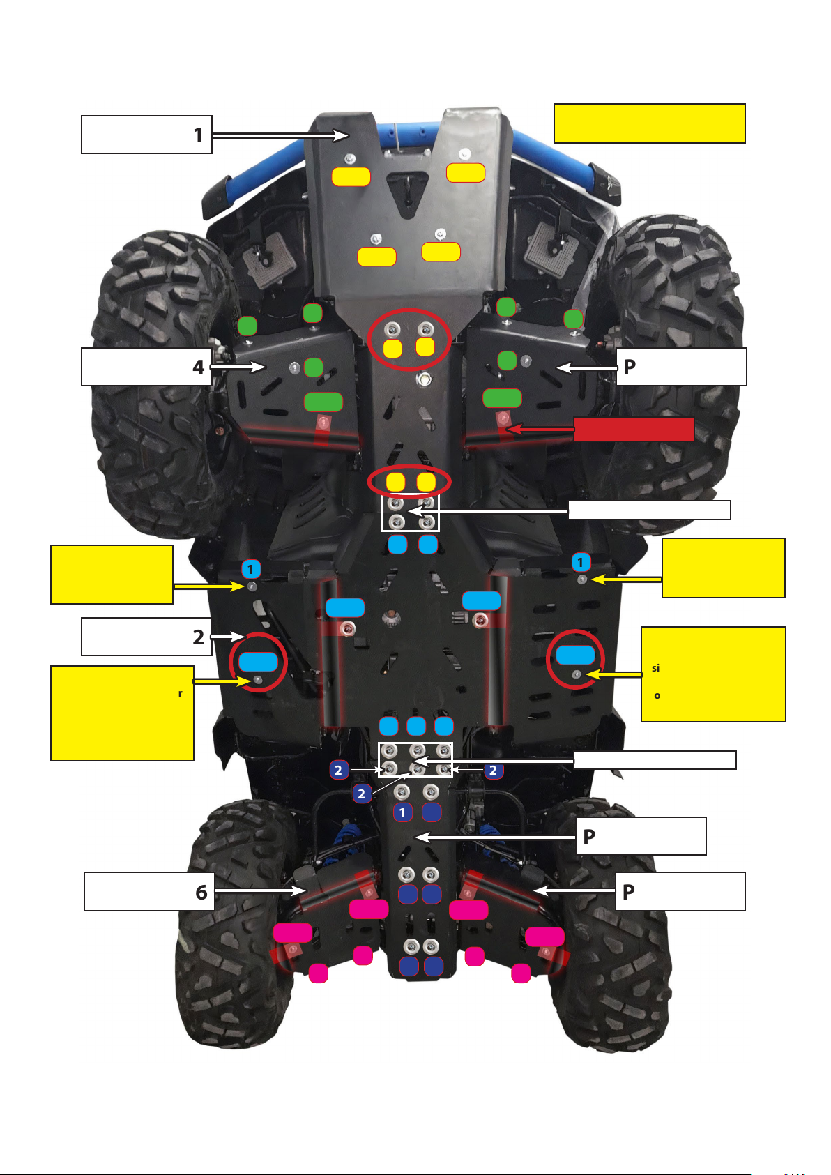
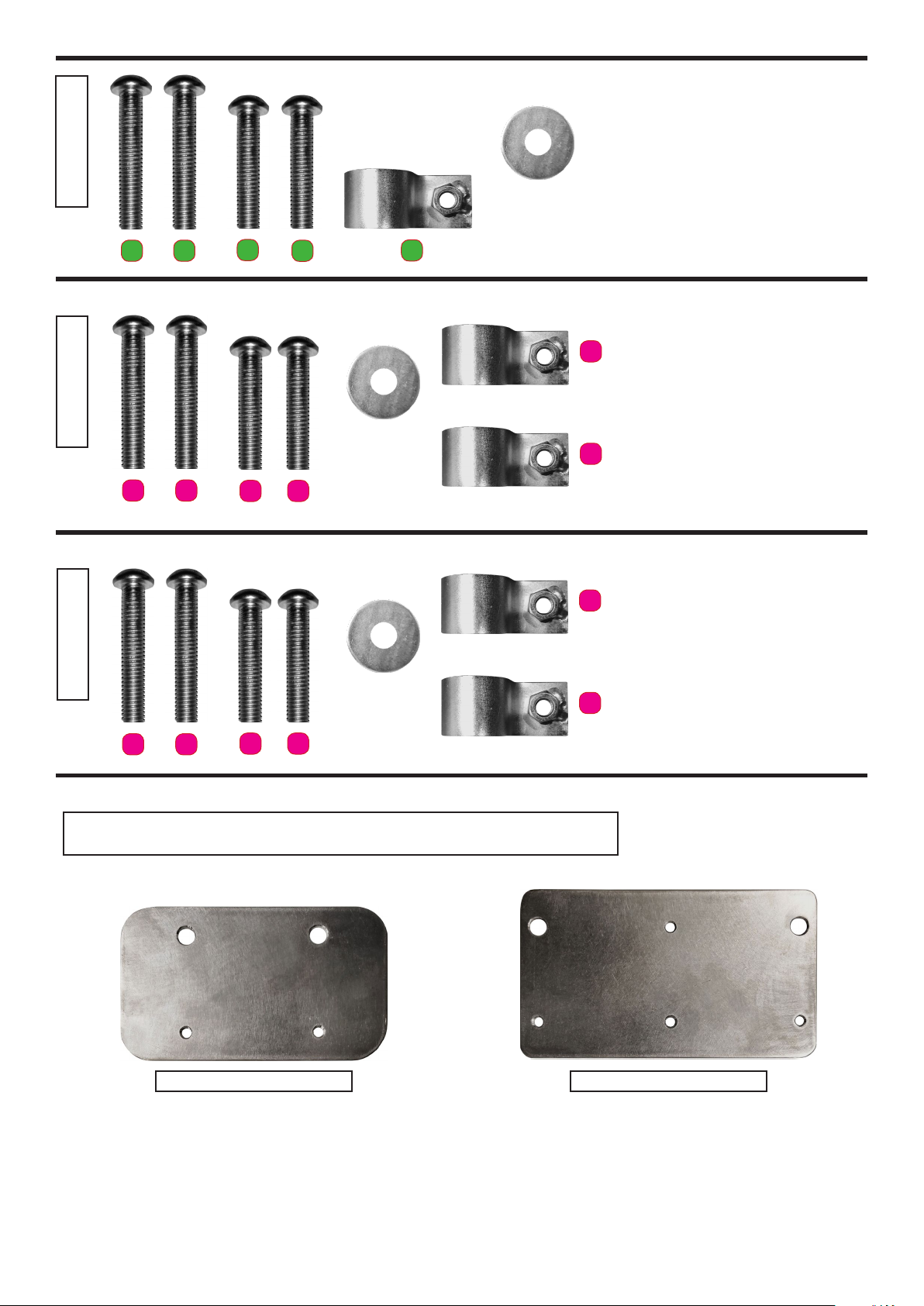
Start the assembly sequence with the front plate [1] and the fastening plate A1.
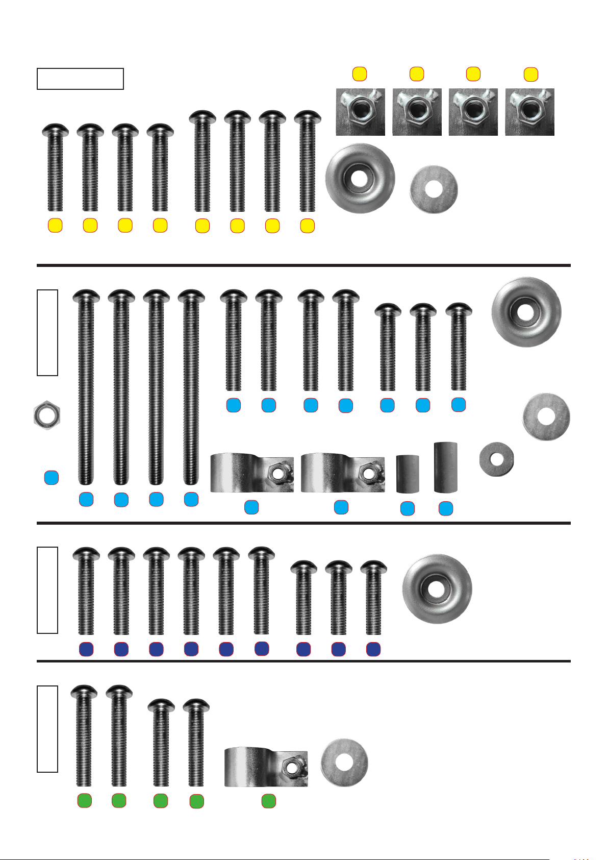
INSTALLATION OF PROTECTIVE PLATES 1, 2, 3, 4, 5, 6, 7
[Plate no. 1] When assembling the protective plate, do not unscrew the front metal plate that comes with your ATV. Start from
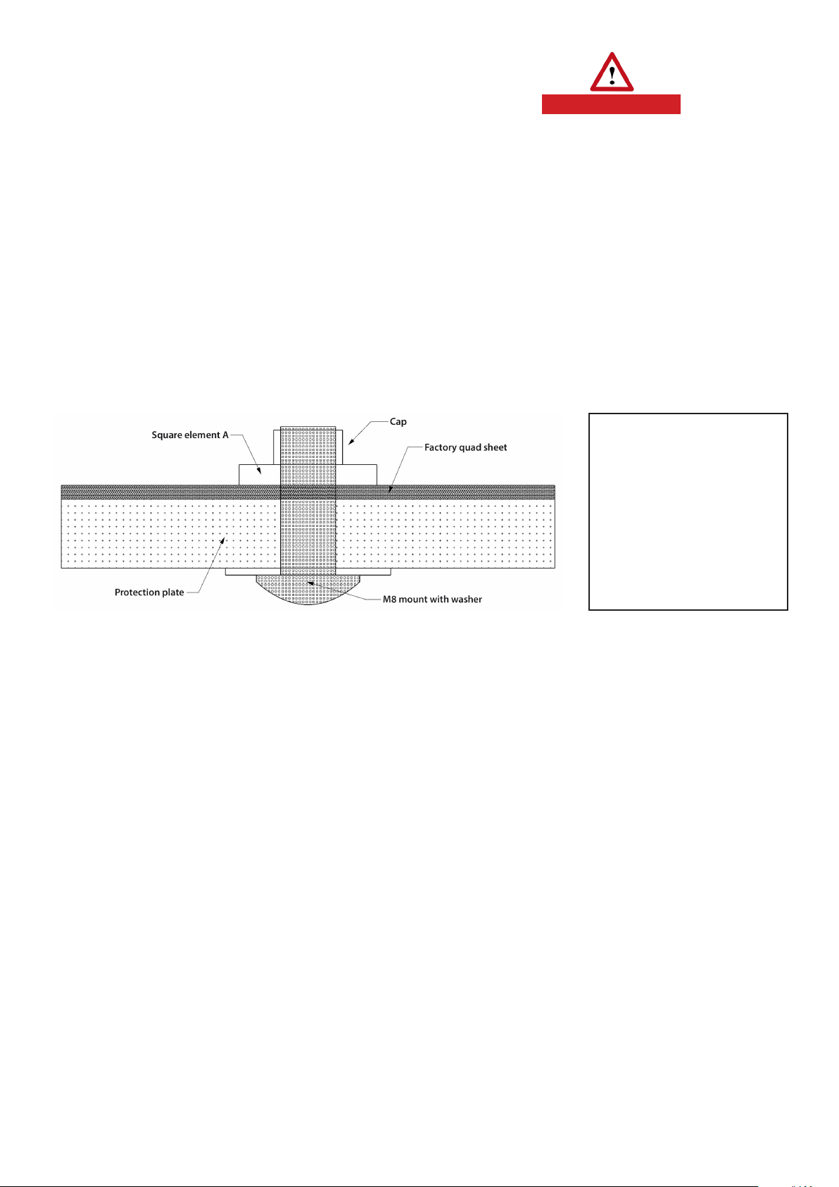
tightening the M6 screws (points marked with red circles on the diagram) then perform the fastening with M8 screws, which
screw is marked in yellow on the diagram as screw no. 1 with square elements A (Fig. 3). Scheme 1+A. The last step is screwing
the connecting plate A1. The mounting plate is installed between the screwed-on plastic cover and the quad’s chassis.
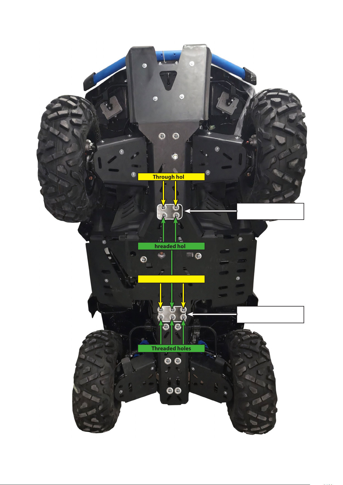
[Plate no. 2] Place the washers on the screws. Screw in from above through the outer feet of the leg space. Install two hooks
and screw 2-3 threads into the center protection plate, the hooks will hold the plate on the quad frame. Install the plate on the
screws located in the leg space. Put washers on the bolts, then the nuts Btwisting with your ngers. Attach the tabs through
the square holes to the frame tubes, tighten, so that the tabs do not fall out. Then adjust the position of the plate, place
the mounting plate A2 and tighten it. NOTE Place the distance sleeves Con the bolt behind the protective plate (points marked
with red circles in the diagram).
[Plate no. 3] Place the back protection plate over the appropriate holes and install the screws with washers. Before tightening
the bolts, set the rear protection plate to the correct position and then fully tighten all 9 bolts.
[Plate no. 4 and 5] First, put the cover and install the hooks (orientation on the diagram) to the front rocker arms covers,
do not fully tighten the screws, center the cover on the appropriate holes and tighten the screws, not forgetting the washers :-).
Position the cover and tighten the screws. Make a double check, if there is no contact between the wheel and the guard
by turning your steering wheel completely right and left, in the event of a contact, make the proper adjustment of the guard by
moving it to the correct position. Also check, if there is sucient space between the front protection plate and the rocker arm
covers to avoid contact in the event of complete compression of the suspension.
[Plate no. 6 and 7] First, put the cover and install the hooks (orientation on the diagram) to the rear rocker arms covers,
do not fully tighten the screws, center the cover on the appropriate holes and tighten the screws, not forgetting the washers :-).
Position the cover and tighten the screws. Make a check that there is no contact between the wheel and the guard by turning
your steering wheel completely right and left, in the event of a contact, make the proper adjustment of the guard by moving it
to the correct position. Also check that there is adequate space between the rear protective plate and the rocker arm covers to
avoid contact in the event of complete compression of the suspension.
INFORMATION
Sucient space for the hands allows mounting clamps of the control arm covers at the marked points after attaching the
cover to them. To do this, tighten the cover with the screws on the front and rear transverse arms (points marked with circles
in the diagram). Clamp the clamp (without the screw on the other side) on the swing arm tube (observe the orientation
of the clamps in the diagram), move the thread to the hole in the protective cover and x the clamp with the screw (Fig. 1 and 2).
Fig. 3 plate [no. 1] INFORMATION
Fastened with M8 screws
with square elements A we carry
out through the notches located
in the factory plate of the quad
cover
CAUTION

Diagram of the arrangement of mounting elements - TGB BLADE 600 LTX
PLATE No. 1
PLATE No. 4
PLATE No. 2
PLATE No. 3
PLATE No. 7PLATE No. 6
PLATE No. 5
1+A
1+A 1+A
2
1
2/A 2/A
1
3333
2
2 2
11
3/A
3/A
4
2 2
1 1
11
1 1
2
1/A
1/A
1/A
1/A
2
2
2
2
4 4
2
2
1+A
Symbol of the hooks
on the rocker
Mounting plate A1
Mounting plate A2
Tighten the M6 nut (B)
on the bolt on
the upper side
Tighten the M6 nut (B)
on the bolt on
the upper side
Tighten the M6 nut (B)
on the bolt on the upper
side of the ATV. Place the
left distance sleeve C
on the screw behind the
protective plate
Tighten the M6 nut (B)
on the bolt on the upper
side of the ATV. Place the
right distance sleeve C
on the screw behind the
protective plate
Elements A for mounting
from the inside Fig. 3
1/B/C 1/B/C

Arrangement of mounting plates connecting the protective plates - TGB BLADE 600 LTX
Mounting plate A2
assembled from the inside
Mounting plate A1
assembled from the inside
Threaded holes
Threaded holes
Through holes
Through holes

List of mounting elements - TGB BLADE 600 LTX
WASHER
36 mm M6/M8
4 pcs.
WASHER
24 mm M8
4 pcs.
WASHER
24 mm M8
4 pcs.
WASHER
18 mm M6
4 pcs.
for M6 nuts
28 mm
left
33 mm
right
M6 NUT
4 pcs.
WASHER
36 mm M6/M8
7 pcs.
WASHER
24 mm M8
4 pcs.
1
1
33A
21
11 1
2
A A
B
234 4 4
3
111 2 2 2 2
A A A A
WASHER
36 mm M6/M8
9 pcs.
1 1 1 1
112 2 2
PLATE No. 2PLATE No. 3PLATE No. 4
PLATE No. 1
CC
M8/30mm
M6/70mm
M6/70mm
M6/70mm
M6/70mm
M8/30mm
M8/30mm
M8/30mm
M6/35mm
M6/35mm
M6/35mm
M8/35mm
M8/35mm
M6/30mm
M6/30mm
M6/30mm
M6/30mm
M6/35mm
M8/35mm M6/30mm
M6/30mm
M6/30mm
M6/30mm
M6/30mm
M6/30mm
M6/30mm
M6/25mm
M6/25mm
M6/25mm
M6/35mm
M6/35mm
M6/35mm

MOUNTING PLATES TGB BLADE 600 LTX
WASHER
24 mm M8
4 pcs.
WASHER
24 mm M8
4 pcs.
WASHER
24 mm M8
4 pcs.
33A
21
2
2
2
2
A
A
A
A
1
1
1
1
MOUNTING PLATE A1 MOUNTING PLATE A2
PLATE No. 5
PLATE No. 6
PLATE No. 7
PROTECTIVE PLATES USE
You have just set up your hood, uh, it wasn’t that bad. During the crossings - when using, watch out for protruding stones, trunks
or roots. Remove the mud after the expedition easily with a pressure washer, a water hose, for this activity you do not have
to turn your ATV upside down, because the mud does not stick to the protective plates made of HrdPE material. Although
our HrdPE covers themselves oat on the water, remember that when the water level is too high, they will not carry your quad
on it. We recommend to watch the lms :-)
M6/35mm
M8/35mm
M8/35mmM8/35mm
M8/35mm M8/35mm
M6/30mmM6/30mm
M6/30mm M6/30mm
M6/30mm
M6/30mm
Table of contents