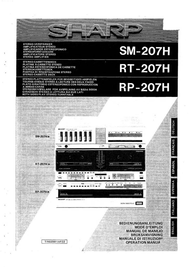
Sharp SM-307H User manual

SHARP
SERVICE
MANUAL
/SERVICE-ANLEITUNG/
MANUEL
DE
SERVICE
$3736SM307HBK
SM-307H
(BK}
PHOTO:SM-307H(BK)
@
In
the
interests
of
user-safety
the
set
should
be
restored
to
its
]
original
condition
and
only
parts
identical
to
those
specified
be
used.
e
im
Interesse
der
Benutzer-Sicherheit
sollte
dieses
Gerat
wieder
auf
seinen
ursprunglichen
Zustand
eingestellt
und
nur
die
vor-
geschriebenen
Teile
verwendet
werden,
@
Dans
I'intérét
de
la
sécurité
de
|’utilisateur,
I‘appareil
devra
étre
reconstituté
dans
sa
condition
premiére
et
seules
des
piéces
identiques
a
celles
spécifiées,
doivent
étre
utilisées.
INDEX
TO
CONTENTS
=
(
©
Page
SPECIFICATIONS
.......
2...
cece
eee
eee
enna
2
EQUIVALENT
CIRCUIT
(BLOCK
DIAGRAM)
NAMES
OF
PARTS
........
2.
cece
eee
cence
eeee
2
OFAC
jstiucureiniiesne
tart
aieltinght
Wee
caeassuncilets
27-29
DISASSEMBLY
..........0
ccc
cece
cece
tect
eenees
4
TYPES
OF
TRANSISTOR
AND
LED
.............
29
BLOCK
DIAGRAM
.........
2c
ccc
cece
eee
e
ee
eees
6
WIRING
OF
PRIMARILY
SUPPLY
CIRCUIT
DESCRIPTION
.............0
000
c
eee
7-14
LEADS
(FOR
UK)
...
0.0
ee
ceeeeee
30
NOTES
ON
SCHMATIC
DIAGARM
..............
15
PACKING
METHOD
(FOR
Uk)
..............00005
30
EXPLODED
VIEW
...........
0.2
16
REPLACEMENT
PARTS
LIST................
31-35
SCHEMATIC
DIAGRAM/WIRING
SIDE
SERVICE
INFORMATION
...........
0.000
eevee
36
OF
P.W.BOARD
...........
0.
cece
eee
eee
17-26
INHALTSVERZEICHNIS
O
Seite
TECHNISCHE
DATEN
............-..
22
ee
ee
eee
3
SCHEMATISCHER
SCHALTPLAN/VERDRAH-
BEZEICHNUNG
DER
TEILE
...................0..
3
TUNGSSEITE
DER
LEITERPLATTE
...........
17-26
ZERLEGEN
s-sc:5scctiiaceltiei
ad
Sean
deems
ees
oss
5
ERSATZSCHALTKREIS
(BLOCKSCHALTPLAN)
BLOCKSCHALTPLAN
..............
0c
cece
eee aee
6
DES
INTEGRIERTEN
SCHALTKREISES
......
27-29
KREISBESCHREIBUNG
..................005.
7-14
TRANSISTOREN-UND
ANMERKUNGEN
ZUM
SCHEMATISCHEN
LEUCHTDIODENTYPEN
...............0
00050
29
SCHALT
PLAN?)
sticcvctetet
soundats Acataatt
sat
diac
15
ERSATZTEILLISTE
.........
0.
cee
cece
31-35
EXPLOSIONSDARSTELLUNG
................0.
16
SERVICEINFORMATION
..............
000000
36
©)
TABLE
DES
MATIERES
Page
CARACTERISTIQUES
....0..0..00000cc00sseeeceaes
3
DIAGRAMME
SCHEMATIQUE/COTE
NOMENCLATURE
...............
2.
ee
eee eee
eee
3
CABLAGE
DE LA
PLAQUETTE
DEMONTAGE
.........
0.0 ccc
cece
cece
ences
5
DE
MONTAGE
IMPRIME.................4.
17-26
DIAGRAMME
SYNOPTIQUE
.................--.
6
CIRCUITS
EQUIVALENTS
(DIAGRAMME
DESCRIPTION
DU
CIRCUIT...................
7-14
SYNOPTIQUE)
DE
Cl
...................005
27-29
REMARQUES
CONCERNANT
LE
DIAGRAMME
TRANSISTOR
ET
LED
..........
0.0...
c
cece
eens
29
SCHEMATIQUE
..........
0.
eee
cece
eee
15
LISTE
DES
PIECES
DE
RECHANGE
..........
31-35
ae
EN
BCRATE
io
cus
rte
se
dcian
dr
aac
nteds
16
INFORMATION
DE
SERVICE
................0..
36
ane
SHARP
CORPORATION

SM-307H
FOR
A
COMPLETE
DESCRIPTION
OF
THE
OPERATION
OF
THIS
UNIT,
PLEASE
REFER
TO
THE
OPERATION
MANUAL.
SPECIFICATIONS
Power
consumption:
280W
Power
source:
AC
220V,
50/60
Hz
(For
Europe)
AC
240V,
50
Hz
(For
UK)
MPO:
4
x
50
W/8
ohms
0.8%
total
harmonic
distortion
RMS:
Total
120
W
Full
range/Bass
range;
2
x
30
W
at
8
ohms,
0.8%
T.H.D.
(DIN
45
500)
Input
sensitivity
and
VCR/CD/TV;
300
mV,
47
kohms
input
impedance:
Phono;
3
mV,
47
kohms
Tape/Tuner;
220
mV,
47
kohms
Loaded
impedance:
Speakers;
8
ohms
Headphones;
8
-
25
ohms
Dimensions:
Width;
330
mm
(13’’)
Height;
107
mm
(4-3/16’’)
Depth;
329
mm
(12-15/16’’)
Weight:
6.5
kg
(14.4
Ibs.)
|
Specifications
for
this
model
are
subject
to
change
|
without
prior
notice.
NAMES
OF
PARTS
-
Spectrum
Analyzer
and
Graphic
Equalizer
Display
.
Spectrum
Analyzer/Graphic
Equalizer
Selector
Switch
.
Function
Selector
Switches
and
Indicators
.
Graphic
Equalizer
Flat
Button
.
Bass
Level
Control
.
Balance
Control
.
Volume
Control
.
Mode
Switch
»
Surround
Switch
.
Power
Switch
.
Graphic
Equalizer
Up/Down
Buttons
10
11
12
13
14
15
16
17
18
-
Spectrum
Analizer
Display
Level
Control
.
Graphic
Equalizer
Memory
Button
.
Graphic
Equalizer
Manual/Programmed
Selector
Figure
2-1
.
Graphic
Equalizer
Preset
Buttons
.
Headph
Socket
anaaaean
meaao
19
20
21
22
23
24
25
26
»
Microphone
Socket
-
Mixing
Level
Control
.
Tape
Input/Output
Socket
.
CD
Sockets
»
TV
Input
Socket
-
VCR
Input
Socket
»
Tuner
Input
Socket
.
Phono
Input
Socket
.
Speaker
Socket
.
AC
Power
Supply
Cord
Ne
ee
ee
ee
ey
CHO
MDNODODAWN=|"OODNOUAWNH
N
=
NNNNN
Onhwh
Figure
2-2

O
EINE
VOLLSTANDIGE
BESCHREIBUNG
DER
BEDIE-
NUNG
DIESES
GERTES
IST
IN
DER
BEDIENUNGS-
ANLEITUNG
ENTHALTEN.
TECHNISCHE
DATEN
Leistungsaufnahme:
280
W
Spannungsver-
Netzspannung
220
V,
50/60
Hz
(Fur
sorgung:
Europa)
Netzspannung
240
V,
50
Hz
(Fur
das
,
Vereinigte
K6nigreich)
Hochmusikleistung:
4
x
50
W/8
Ohm
0,8
%
Gesamtklirrfaktor
Effektivwert:
Gesamt
120
W
voller
Frequenzbereich/Babereich;
2
x
30
W
bei
8
Ohm,
Gesamtklirrfaktor
0,8
%
(DIN
45
500)
Eingangsempfind-
VCR/CD/TV;
300
mV,
47
kOhm
lichkeit
und
-
phono;
3
mV,
47
kOhm
impedanz:
Tape/Tuner;
220
mV,
47
kOhm
Balastungsim-
Lautsprecher;
8
Ohm
pedanz:
Kopfhoérer;
8
-
25
Ohm
Abmessungen:
Breite;
330
mm
Hohe;
107
mm
Tiefe;
329
mm
Gewicht:
6,5
kg
SM-307H
©
POUR
LA
DESCRIPTION
COMPLETE
DU
FONCTION-
NEMENT
DE
CET
APPAREIL,
SE
REPORTER
AU
MODE
D'EMPLOI.
CARACTERISTIQUES
Consommation:
280
W
Alimentation:
CA
220
V,
50/60
Hz
(en
Europe)
CA
240
V,
50
Hz
(au
Royaume-Uni)
MPO:
4
x
50W/8
ohms
0,8
%
de
distorsion
harmonique
totale.
RMS:
Total
120
W
Gamme
totale/gamme
basse;
2
x
30
W
a
8
ohms,
0,8
%
de
distorsion
harmo-
nique
totale
(DIN
45
500)
Sensibilité
d’entrée
=VCR/CD/TV;
300
mV,
47
k
ohms
et
impédance
Phono;
3
mV,
47
k
ohms
d’entrée:
Bande/tuner;
220
mV,
47
k
ohms
Impédance
normale:
Enceintes;
8
ohms
Casque;
8
a
25
ohms
Dimensions:
Largeur;
330
mm
Hauteur;
107
mm
Profondeur;
329
mm
Poids:
6,5
kg
Die
technischen
Daten
fur
dieses
Modell
konnen
ohne
vorherige
Ankundigung
Anderungen
unterworfen
sein.
BEZEICHNUNG
DER
TEILD
.
Spektrum-Analysator-
und
Frequenzgangentzerrer-
Anzeige
.
Spektrum-Analysator/Frequenzgangentzerrer-
Wahlischalter
.
Funktionswahischalter
und
-Anzeigen
.
Flache
Taste
fiir
Frequenzgangentzerrer
.
BaRpegeisteller
.
Balancesteller
.
Lautstarkesteller
.
Betriebsartenschalter
.
Surround-Schalter
10.
Netzschalter
11.
Frequenzgangentzerrer-Auf/Ab-Schalter
12.
Spektrum-Analysator-Anzeigepegelsteller
13.
Frequenzgangentzerrer-Speichertaste
14.
Manuell/Programmierbarer
Frequenzgangentzerrer-
Wahlschalter
15.
Frequenzgangentzerrer-Vorwahitasten
16.
Kopthérerbuchse
17.
Mikrofonbuchse
18.
Mischpegelsteller
19.
Tonbandgerateingangs-
/ausgangsbuchse
20.
CD-Buchsen
21.
Tv-Eingangsbuchsen
22.
VCR-Eingangsbuchsen
23.
Tuner-Eingangsbuchsen
24.
Phono-Eingangsbuchse
25.
Lautsprecheranschliisse
26.
Cordon
secteur
—b
OOMDNOOhW
Nh
Les
caractéristiques
de
ce
modéle
sont
sujettes
a
modification
sans
préavis.
NOMENCLATURE
.
Affichage
de
l’analyseur
spectral
et
de
|’égaliseur
gra-
phique
.
Commutateur
de
sélection
analyseur
spectral/égaliseur
graphique
.
Sélecteurs
de
fonction
et
voyants
-
Touche
plate
de
!’égaliseur
graphique
.
Commande
de
niveau
des
basses
.
Commande
de
balance
»
Commande
de
volume
.
Commutateur
de
mode
.
Commutateur
d’encadrement
.
Interrupteur
marche/arrét
-
Touches
de
montée/descente
de
I‘égaliseur
graphique
.
Commande
de
niveau
de
I’affichage
pour
I’égaliseur
gra-
phique
-
Touche
de
mémoire
de
I'égaliseur
graphique
.
Sélecteur
manuel/programmé
de
I’égaliseur
graphique
-
Touches
de
présélection
de
I’égaliseur
graphique
.
Prise
de
casque
.
Prise
de
microphone
-
Commande
de
niveau
de
mixage
.
Douille
d’entrée/sortie
de
bande
-
Douilles
CD
.
Douilles
d’entrée
TV
.
Douilles
d’entrée
VCR
.
Douille
d’entrée
tuner
.
Douille
d’entrée
phono
.
Bornes
d’enceintes
.
Netzkabel
_—
|
N]-OOONIOOARW
HO
=
Nw
2
Vaan
a
CODNOTAW
NNNNNND
OOhWNH—

SM-307H
©
DISASSEMBLY
Caution
on
Disassembly
Follow
the
below-mentioned
notes
when
disassem-
bling
the
unit
and
reassembling
it,
to
keep
its
safety
and
excellent
performance:
(A)
x2
1.
Be
sure
to
remove
the
power
supply
plug
from
the
wall
outlet
before
starting
to
disassemble
the
unit.
2.
Take
off
nylon
bands
or
wire
holders
where
they
need
be
removed
when
disassembling
the
unit.
After
servicing
the
unit,
be
sure
to
rearrange
the
leads
where
they
were
before
disassembling.
3.
Take
sufficient
care
on
static
electricity
of
integrated
circuits
and
other
circuits
when
servicing.
4
x6mm
(C)X3
(D)X4
Cobinet
Figure
4-1
STEP
REMOVAL
PROCEDURE
FIGURE
1
Cabinet
1.
Screw...
.....
eee
(A)x5;
4—1
|
2
Bottom
Plate
1.
Screw...
...
00.0008
(B)x8
|
4—2
3
Front
Panel
1.
Knob..............
(C)x3
|
4-1
2.\Nut
o.oo
oes
ciens4
(D)x1
3.
Screw........2..0.
(E)x5
|
4—2
4.
Socket
............
(G)x7|
4-3
{4
ee
a
er,
Oe
Sf
4.
Control
P.W.B
Te
IOs
eu
G
ease
ates
(H)x3
|
4—5
5.
Switch
P.W.B
Headphones
P.W.B
7.
Indicator
P.W.B
1.
Screw.............
{K)x4.|
4—4
QZ
AOOK
seach
clevided
oie
(L)x13
8.
Socket
P.W.B
1.Screw
.........-..
(M)x12]|
4—4
(G)X1
*
1.
Each
P.W.B.
should
be
removed
until
the
parts
to
be
(G)X1
Ln
Baxi
|=-
(}
SOCKES
oy
SOCKET
SOCKET
exchanged
can
be
removed
when
servicing.
If
the
d
(G)x!
isi
parts
to
be
exchanged
are
in
the
exchangeable
(G)x1
GOK)
Ne
Qf
SOCKET
condition,
the
rest
of
P.W.Bs.
need
not
to
be
removed.
aoa
SOCKET
t
a
a
[S|
INDICATOR
PWB
Figure
4-3
(L)X13
(H)
x3
SOCKET
PWB
HEADPHONES
Ww
PWB
cs
e
To
remove
the
knob,
remove
the
headphone
PWB.
Figure
4-5
¢
To
remove
the
socket
PWB,
at
first
remove
the
power
transformer,
and
then
shift
it.
Figure
4-4
(Md
x12
#3X8mm
—4~

SM-307H
SM-307H
O
ZERLEGEN
©
DEMONTAGE
Précautions
pour
le
démontage
Lors
du
démontage
de
I’appareil
et
de
son
remontage,
suivre
les
précautions
ci-dessous,
pour
maintenir
la
Vorsichtsmassregeln
fiir
das
zerlegen
Beim
Zerlegen
und
Zusammenbauen
des
Gerates
die
folgenden
Anweisungen
befolgen,
um
_
dessen
Hz
FOR
UK
PHONES:
MAIN
$0401
o
w
z
6
=
a
REAR
$0402
J201
w
°
=
Zz
°
=
a
«
is
5.
ira
BASS
RANGE
AC
220V,50/60H:
FOR
EUROPE
Betriebssicherheit
und
ausgezeichnete
Leistung
auf-
sécurité
et
d’excellentes
performances.
rl
3
a:
:
:
3
:
rechtzuerhalten.
f
©
®o
©
)
@
3
1.
S’assurer
de
retirer
la
fiche
d’alimentation
secteur
1.
Bevor
mit
dem
Zerlegen
des
Gerates
begonnen
wird,
de
la
prise
murale
avant
de
démarrer
le
démontage
7
.
_
unbedingt
den
Netzkabelstecker
aus
der
Netzsteck-
de
I’appareil.
:
7S
48
g
dose
ziehen.
Bg
“e>
.
Déposer
les
bandes
de
nylon
ou
les
serre-cables
si
28
Z
8
2.
Nylonbander
oder
Leitungshalter
entfernen,
falls
nécessaire
lors
du
démontage
de
l’appareil.
Apres
la
BOP
FES
catia
PEA
Relea
eee
cl
:
dies
beim
Zerlegen
des
Gerdates
erforderlich
ist.
réparation
de
|’appareil,
s’assurer
de
redisposer
les
Be
28
=8
Nach
Warten
des
Gerates
darauf
achten,
die
Leitun-
fils
tel
qu’ils
étaient
avant
le
démontage.
a8
38
;
e
gen
wieder
so
zu
verlegen,
wie
sie
vor
dem
Zerlegen
z
angeordnet
waren.
_
Faire
attention
a
I’électricité
statique
des
circuits
|
$=
j=
$$§8§
©
||
|)
QO
,@Q
intégrés
et
des
autres
circuits
lors
de
la
réparation.
‘lg
5
$l
jses}
[So]
Jeo
.
Beim
Ausfiihren
von
Wartungsarbeiten
auf
sta-
a
ec}
ese]
[23]
[#582
tische
Elektrizitat
der
integrierten
Schaltkreise
und
#3]
[ess]
[es]
[e738
anderen
Schaltungen
achten.
7
<
Plaque
de
base
Panneau
avant
15Vv
16v
23v
-18V
+12v
+12v
2
FLUORESCENT
ACSV
DISPLAY
TUBE
020!
205
($0101)
STAND
.BY
POWER
CIRCUIT
a
w
>
=
«
°
1c201
RP-307H
AMP
CONTROLLER
FLUORESCENT
OISPLAY
TUBE
TO
TAPE
DECK
RT-307H(SO104)
BAL
ANCE
vR202
G2}
co
G3]
TAPE
P.M.1
de
commande}
1.
Crochet
P.M.|
de
i
commutateur
P.M.I
casque
P.M.I
Indicateur
os
1C206
(1/4)
MIXER
Gait
f
MAIN
VOLUME
vR201
a---
a
FUNCTION
DISPLAY
LEVEL
INDICATOR
LED204
GRAPHIC
EQUALIZER
1C205
Kopfhorer
Leiterplatte
P.M.1
de
douille
GRAPHIC
EQUALIZER
VOLUME
GRAPHIC
EQUALIZER
10204
1209
~
241
INVERTER
*
1.
Chaque
P.M.I.
doit
6tre
déposée
jusqu’
a
l’échange
de
piéces
de
P.M.I.
Si
l’échange
de
piéces
est
possible,
on
n’a
pas
besoin
de
déposer
les
autres
P.M.I.
DISPLAY
TUBE
FLUORESCENT
ORIVER
_—_
Vi
FLUORESCENT
DISPLAY
TUBE
*
1.
Die
einzelnen
Leiterplatten
sollten
entfernt
werden,
&Potinccatical
I
ieee
Ga
waldvers
la
PN
de
casas?
bis
die
zu
auswechselinden
Teile
bei
der
Wartung
¢
Pour
retirer
la
P.M,
liberer
le
transformateur
d’aliméntation
et
$
entfernt
werden
konnen.
Wenn
die
zu
auswechseln-
déplacer
ce
dernier.
MODE
SWITCH
den
Teile
in
auswechselbarem
Zustand
sind,
ist
es
nicht
erforderlich,
die
restlichen
Leiterplatten
zu
entfernen.
e
Um
den
Knopf
zu
entfernen,
den
Kopfhorer
PWB
entfernen.
e
Um
die
Buchse
PWB
zu
entfernen,
zuerst
den
Netztransformator
entfernen
und
dann
verschieben.
Figure
6
BLOCK
DIAGRAM
=6§2

©
List
of
Input
Changing
Analog
Switch
IC
Terminals
(LC7823)
Pin
No.|
Pin
Name
Function
SM-307H
SM-307H
List
of
Graphic
Equalizer
Switching
IC
Terminals
(LC7520)
Pin
No.|
Pin
Name
Function
R-ch
tuner
input
R-ch
tape
input
R1,
R2
common
output
terminal
R-ch
CD
input
R-ch
player
input
R1,
R2
common
output
terminal
R-ch
TV
input
R-ch
VCR
input
R5,
R6
common
output
terminal
Not
used
Not
used
Power
supply
terminal
(-15V)
Microcomputer
data/chip
enabling
Microcomputer
data
signal
input
Microcomputer
clock
signal
input
Connect
to
GND
terminal
Connect
to
GND
terminal
Reset
input
Power
supply
terminal
(+15
V)
Not
used
Not
used
L5,
L6
common
output
terminal
L-ch
VCR
input
L-ch
TV
input
L3,
L4
common
output
terminal
L-ch
player
input
L-ch
CD
L1,
L2
common
L-ch
tape
input
L-ch
tape
input
Fale
1
IN1
Audio
signal
input.
Connect
to
operational
amplifier
(for
graphic
equalizer)
inverting
input
terminal
Connect
to
operational
amplifier
(for
graphic
equalizer)
inverting
input
terminal
Connection
terminal
of
filter
of
each
Band
for
R-ch
Power
supply
for
audio
signal
(Connect
to
+15V)
Selection
terminal
when
2
chips
are
used.
Power
supply
(+
10V)
Power
supply
(+
5V)
Test
terminal
for
internal
IC
Not
used
Input
clock
signal
from
microcomputer
Input
data
signal
from
microcomputer
Connect
to
GND
terminal
Power
supply
for
audio
signal.
(Connect
to
-15
V)
Connection
terminal
of
filter
of
each
Band
for
L-ch
Connect
to
operational
amplifier
(for
graphic
equalizer)
non-inverting
input
terminal
Audio
input.
Connect
to
operational
amplifier
(for
graphic
equalizer)
inverting
input
terminal
O
Liste
von
Klemmen
des
integrierten
Schaltkreises
des
Analogschalters
fiir
Eingabetiberwechsel
(LC7823)
Stiftsbe-
zeichnung
Funktion
Liste
von
Klemmen
des
integrierten
Schaltkreises
der
Frequenzgangentzerrerumschaltung
(LC7520)
Stiftsbe-
zeichnung
Funktion
1
R1TU
2
R2TA
3
RCOM1
4
R3CD
5
R4PH
6
RCOM2
7
R5TV
8
R6VCR
9
RCOM3
10
R7
11
RCOM4
12
VEE
13
CE
14
D1
15
CL
18
|
RES
19
|
VDD
20
LCOM4
21
|
L7
22
|
LCOM3
23
L6VCR
24
|
LS5TV
25
|
LCOM2
26
L4PH
R-Kanal
Tunereingangssignal
R-Kanal
Bandeingangssignal
R1,
R2
Gemeinsame
Ausgabeklemme
R-Kanal
CD-Eingangssignal
R-Kanal
Speilereingangssignal
R1,
R2
Gemeinsame
Ausgabeklemme
R-Kanal
Fernsehgerateingangssignal
R-Kanal
VCR-Eingangssignal
R5,
R6
Gemeinsame
Ausgabeklemme
Anschlu&
nicht
belegt.
AnschluB
nicht
belegt.
Netzklemme
(-15
V)
Eingabe
des
Mikrocomputerdaten/Chip-Freigabesignals
Eingabe
des
Mikrocomputerdatensignals
Eingabe
des
Mikrocomputertaktsignals
Anschiu&
an
GND-Klemme
Anschluf§
an
GND-Klemme
Nullstellungseingangssignal
Netzklemme
(+15
V)
AnschluB
nicht
belegt.
Anschlu8
nicht
belegt.
L5,
L6
Gemeinsame
Ausgabeklemme
L-Kanal
VCR-Eingangssignal
L-Kanal
Fernsehgerateingangssignal
L3,
L4
Gemeinsame
Ausgangssignal
L-Kanal
Spielereingangssignal
L-Kanal
CD
L1,
L2
Gemeinsamkeit
L-Kanal
Bandeingangssignal
L-Kanal
Bandeingangssignal
—8—
=
oO
ON
DOO
BP
W
IN1
Eingabe
des
Tonsignals.
Anschiu&
an
Umkehreingabeklemme
des
Betriebsverstarkers
(fur
Frequenzgangentzerrer)
Anschluf
an
Umkehreingabeklemme
des
Betriebsverstarkers
(fur
Frequenzgangentzerrer)
Anschlu&klemme
vom
Filter
jedes
Bandes
fur
R-Kanal
Spannungsversorgung
fur
Tonsignal.
(Anschlu8&
an
+15
V)
Auswahlklemme
beim
Verwenden
von
2
Chips
Spannungsversorgung
(+10
V)
Spannungsversorgung
(+5
V)
Probeklemme
fiir
den
inneren
integrierten
Schaltkreis
Anschiu&
nicht
belegt.
Eingabe
des
Taktsignals
vom
Mikrocomputer
Eingabe
des
Datensignals
vom
Mikrocomputer
Anschluf§
an
GND-Klemme
Spannungsversorgung
ftir
Tonsignal.
(AnschluB
an
-15
V)
Anschlu&klemme
vom
Filter
jedes
Bandes
fur
L-Kanal
Anschlu&
an
Nichtumkehreingabeklemme
des
Betriebsverstarkers
(fur
Frequenzgangenizerrer)
Toneingangssignal.
Anschlu&
an
Umkehreingabeklemme
des
Betriebsverstarkers
(fur
Frequenzgangentzerrer)

®
Liste
des
bornes
IC
des
commutateurs
analogues
pour
la
commutation
d’entrée
(LC
7823)
Nom
de
broche
Fonction
SM-307H
Liste
des
bornes
IC
pour
la
commutation
de
l'égaliseur
graphique
(LC7520)
Fonction
Oo
ON
DT
SP
WN
R1TU
R2TA
RCOM1
R3CD
R4PH
RCOM2
R5TV
R6VCR
RCOM3
R?
RCOM4
VEE
CE
D1
Entrée
du
tuner
de
R-ch
(canal
de
droite)
Entrée
de
bande
de
R-ch
Borne
de
sortie
commune
pour
R1,
R2
Entrée
du
lecteur
de
R-ch
Entrée
du
lecteur
de R-ch
Borne
de
sortie
commune
pour
R1,
R2
Entrée
TV
de
R-ch
Entrée
du
magnétoscope
de
R-ch
Borne
de
sortie
commune
pour
R5,
R6
Non
utilisée.
Non
utilisée.
Borne
d’alimentation
(-15
V)
Entrée
du
signal
de
validation
de
la
puce/données
du
micro-ordinateur
Entrée
de
signal
des
données
du
micro-ordinateur
Entrée
de
signal
d’horloge
du
micro-ordinateur
Connectée
a
la
borne
GND.
Connectée
a
la
borne
GND.
Entrée
de
remise
a
zéro
Borne
d’alimentation
(+15
V)
Non
utilisée.
Non
utilisée.
Borne
de
sortie
commune
pour
L5,
L6
Entrée
du
magnétoscope
de
L-ch
(canal
de
gauche)
Entrée
TV
de
L-ch
Borne
de
sortie
commune
pour
L3,
L4
Entrée
du
lecteur
de
L-ch
CD
de
L-ch
Commune
pour
L1,
L2
Entrée
de
bande
de
L-ch
Entrée
de
bande
de
L-ch
Entrée
de
signal
audio.
Connectée
a
la
borne
d’entrée
d’inversion
de
l’amplificateur
de
fonctionnement
(pour
I'égaliseur
graphique)
Connectée
a
la
borne
d’entrée
d'inversion
de
l'amplificateur
de
fonctionnement
(pour
l'égaliseur
graphique)
Borne
de
connexion
des
filtres
de
bandes
pour
R-ch
(canal
de
droite)
Alimentation
pour
signal
audio.
(Connectée
a
+15
V)
Borne
de
sélection
lors
de
l'utilisation
de
2
puces.
Alimentation
(+10
V)
Alimentation
(+5
V)
Borne
d’essai
pour
IC
interne.
Non
utilisée.
Signal
d’horloge
d’entrée
du
micro-ordinateur
Signal
des
données
d’entrée
du
micro-ordinateur
Connecter
a
la
borne
GND.
Alimentation
pour
signal
audio.
Connecter
a
-
15V.
Borne
de
connexion
des
filtres
des
bandes
pour
L-ch
Connectée
a
la
borne
d’entrée
de
non-
inversion
de
l'amplificateur
de
fonctionnement
(pour
I’égaliseur
graphique).
Entrée
audio.
Connectée
a
la
borne
d’entrée
d'inversion
de
l’amplificateur
de
fonctionnement.
(Pour
l'egaliseur
graphique)

SM-307H
©
List
of
Vacuum
Fluorescent
Tube
(Graphic
Equalizer/Spectrum
Analyzer)
Drive
Microcomputer
Terminals
(LC7565)
Pin
No.|
Pin
Name
ua
Function
TEST
2
Al
A2
A3
A4
AS
AG
A7
A8
AQ
own
Oonrh
WOH
=
Connect
to
vacuum
fluorescent
tube
anode
(drive
output)
Selection
terminal
when
chip
is
used.
Connect
to
GND
terminal
Microcomputer
data
input
terminal
Microcomputer
clock
input
terminal
Connect
to
GND
terminal
Terminal
to
connect
externally
provided
CR
for
oscillation
f1
~
f7
For
setting
the
indication
time
holding
rest
time
T
For
setting
the
indication
time
holding
rest
time
Connect
to
GND
terminal
Input
audio
signal
of
set
band
which
passes
through
B.P.F
with
rectified
voltage
Connect
to
GND
terminal
Connect
to
grid
of
vacuum
fluorescent
tube
(drive
output)
Power
supply
terminal
List
of
Amplifier
Drive
Microcomputer
Terminals
(LC6522C)
Pin
Name
Function
-10—
OnN
OOP
WHY
=
AF1
KO
K1
K2
K3
K4
K5
SENS
REMOTE
POWER
VR
IND
VR
DOWN
VR
UP
SEL
4
(PH)
SEL
3
(CD)
SEL
2
(TA)
SEL
1
(TU)
SEL
6
(VCR}
SEL
5
(TV)
MUTE
1
BASS
VDD
PAO
Connect
to
GND
terminal
Key
matrix
Not
used
Key
matrix
Clock
signal
output
for
control
Data
signal
output
for
control
Chip
enabling
signal
for
control
Not
used
Test
terminal.
Connect
to
GND
terminal
Connect
to
GND
terminal
Clock
oscillation.
Connect
quartz
oscillator.
Not
used
Clock
oscillation.
Connect
quartz
oscillator.
Reset
input
Connect
to
GND
terminal
ON/OFF
Initial/backup/start
judgment/power
down
detection
Not
used
Player
indicator
drive
output
CD
indicator
drive
output
TAPE
indicator
drive
output
TUNER
indicator
drive
output
VCR
indicator
drive
output
TV
indicator
drive
output
Muting
output
Not
used
Power
supply
terminal
Key
matrix

O
Liste
von
Betriebsmikrocomputerklemmen
ftir
Vakuumfluoreszenzlampe
(Frequenzgangentzerrer/
Spektrumanalysator)
(LC7565)
Stiftsbe-
zeichnung
Funktion
TEST
2
Al
A2
A3
A4
AS
A6
A7
A8
AQ
Offnen
Anschlu&
an
Vakuumfluoreszenzlampenanode
(Betriebsausgangssignal)
Auswahiklemme
beim
Verwenden
des
Chips.
Anschlu&
an
GND-Klemme
Klemme
ftir
Mikrocomputer-
dateneingangssignal
Klemme
fur
Mikrocomputer-
takteingangssignal
Anschiu&
an
GND-Klemme
Klemme
des
au®erlich
gestellten
C.R-
Anschliusses
fur
Schwingung
f1
~
f7
Fur
Einstellung
der
Halt-/Nullstell-
Zeit
der
Anzeige
T
Fur
Einstellung
der
Halt-/Nullstell-Zeit
der
Anzeige
Anschlu&
an
GND-Klemme
Eingabe
des
Tonsignals
des
Uber
B.P.F.
passierten
Einstellbereiches
mit
Richtspannung
Anschlu&
an
GND-Klemme
Anschlu&8
an
Gitter
der
Vakuumfluoreszenzlampe
(Betriebsausgangssignal)
Netzklemme
-11-
SM-307H
SM-307H
Liste
von
Verstarkersteuermikrocomputer-Ein-
/
Ausgabe-Klemmen
(LC6522C)
Stiftsbe-
zeichnung
Funktion
AF1
KO
K1
K2
K3
K4
K5
K6
K7
sw2
Swi
SENS
REMOTE
POWER
VR
IND
VR
DOWN
VR
UP
SEL
4
(PH)
SEL
3
(CD)
SEL
2
(TA)
SEL
1
(TU)
SEL
6
(VCR)
SEL
5
(TV)
MUTE
1
BASS
VDD
PAO
Anschlu&
an
GND-Kiemme
Tastenmatrix
AnschtuB
nicht
belegt.
Tastenmatrix
Taktsignalausgabe
fur
Steuerung
Datensignalausgabe
fur
Steuerung
Betriebsfahiges
Signal
des
Chips
fur
Steuerung
AnschluB
nicht
belegt.
Probeklemme.
Anschlu&
an
GND-Klemme
Anschlu&
an
GND-Klemme
Taktschwingung.
AnschlieRen
Quarzoszillator
AnschluB
nicht
belegt.
Taktschwingung.
AnschlieRen
Quarzoszillator
Nullstellungseingangssignal
Anschlu8&
an
GND-Klemme
EIN(ON)/AUS(OFF)
Initial/Stutzung/Starturteil/
Niederleistungsnachweis
Anschlu&
nicht
belegt.
PLAYER-Anzeige-Betriebsausgangssignal
CD-Anzeige-Betriebsausgangssignal
TAPE-Anzeige-Betriebsausgangssignal
TUNER-Anzeige-Betriebsausgangssignal
VCR-Anzeige-Betriebsausgangssignal
TV-Anzeige-Betriebsausgangssignal
Stummausgangssignal
Anschlu8
nicht
belegt.
Netzkiemme
Tastenmatrix
©
Liste
des
bornes
du
micro-ordinateur
pour
l‘entrainement
du
tube
fluorescent
(égaliseur
graphique/analyseur
spectral)
(LC7565)
Nom
de
broche
Fonction
TEST2
Al
A2
A3
A4
Ad
A6
A7
A8
AQ
oOwmnon
On
fF
WN
|
Ouverture
A
connecter
a
!‘anode
du
tube
fluorescent
(sortie
d’entrainement).
Borne
de
sélection
pour
l'utilisation
de
puces.
Connectée
a
GND.
Borne
d‘entrée
des
données
du
micro-
ordinateur
Borne
d’entrée
d’horloge
du
micro-
ordinateur
Connectée
a
la
borne
GND.
Borne
de
connexion
CR
externe
pour
l'oscillation
f1
~
{7
Borne
pour
le
réglage
des
temps
de
maintien
et
de
remise
a
zéro
T
Borne
pour
le
réglage
des
temps
de
maintien
et
de
remise
a
zéro
Connectée
a
la
borne
GND.
Entrée
de
signal
audio
des
fréquences
programmées
qui
sont
passées
par
Ia
filtre
passe-bas.
L’entrée
est
faite
avec
la
tension
redressée.
Connectée
a
GND.
A
connecter
a
la
grille
du
tube
fluorescent
(sortie
d'entrainement).
Borne
d’alimentation
Liste
des
bornes
E/S
du
micro-ordinateur
de
commande
de
I’amplificateur
(LC6522C)
Fonction
2
OW
MONAT
GB
WH
—12—
Sw2
Swi
SENS
REMOTE
POWER
VR
IND
VR
DOWN
VR
UP
SEL
4
(PH)
SEL
3
(CD)
SEL
2
(TA)
SEL
1
(TU)
SEL
6
(VCR)
SEL
5
(TV)
MUTE
1
BASS
VDD
PAO
Connectée
a
la
borne
GND.
Matrice
de
touche
Non
utilisée.
Matrice
de
touche
Sortie
de
signal
d'horloge
pour
ta
commande
Sortie
de
signal
de
données
pour
la
commande
Signal
de
validation
de
la
puce
pour
la
commande
Non
utilisée.
Borne
d’essai
4
connecter
a
la
borne
GND.
Connecter
&
la
borne
GND.
Oscillation
d’horloge.
Connecter
l’oscillateur
a
quartz.
Non
utilisée.
Oscillation
d’horloge.
Connecter
|‘oscillateur
4
quartz.
Entrée
de
remise
a
zéro
Connecter
a
la
borne
GND.
marche/arrét
Détection
initial.
/protection/jugement
de
départ/chute
de
puissance
Non
utilisée.
Sortie
d’entrainement
des
voyants
du
tourne-disque
Sortie
d‘entrainement
des
voyants
CD
Sortie
d’entrainement
des
voyants
TAPE
Sortie
d’entrainement
des
voyants
TUNER
Sortie
d’entrainement
des
voyants
du
magnétoscope
Sortie
d’entrainement
des
voyants
du
téléviseur
Sortie
de
réglage
silencieux
Non
utilisée.
Borne
d’alimentation.
Matrice
de
touche

©
Surround
Circuit
The
surround
system
of
this
model
is
a
modified
version
of
the
speaker
matrix
system.
Amplifiers
A
and
B
are
the
power
amplifiers,
to
the
output
terminals
of
which
the
front
speakers
(L-channel
and
R-channel)
are
connected
respectively.
As
the
rear
speakers
(L-channel
and
R-channel)
are
connected
in
series
to
the
output
terminals
of
the
amplifiers
A
and
B,
there
is
produced
a
difference
of
the
output
for
the
amplifiers
A
and
B
and
it
is
applied
to
the
rear
speakers
(L-channel
and
R-
channel)
providing
L-channel
output
and
R-channel
output
reverse
in
phase
to
each
other.
When
the
surround
switch
is
turned
on,
the
output
of
the
amplifier
A
passes
the
resistors
Rs1,
RS2
and
is
reversed
in
phase
to
enter
the
amplifier
B,
resulting
in
an
enhanced
matrix
effect.
Supposed
that
the
input
to
the
amplifier
is
Vi,
the
output
signals
of
the
front
speakers
are
Lf
and
Rf,
the
output
signals
of
the
rear
speakers
are
LB
and
RB,
and
the
amplifier
gain
is
K
(with
the
surround
switch
turned
off),
the
following
equations
will
be
available.
1.
In
case
the
surround
switch
is
turned
off;
e
When
the
signals
to
be
supplied
to
the
amplifiers
A
and
B
are
the
same
in
phase;
Lt
=
Rf
=
KVi
(1—1)
e
When
those
signals
are
reverse
in
phase
to
each
other;
Lt
=
-Rf
=
KVi
(1—2)
2.
In
case
the
surronund
switch
is
turned
on;
e
When
the
signals
to
be
supplied
to
the
amplifiers
A
and
B
are
the
same
in
phase;
Lt
=
Rt
=
KVi
LB
=
RB
=
O(2-1)
e
When
those
signals
are
reverse
in
phase
to
each
other;
Lt
=
-Rf
=
KMVi
2
Le
=-Re=KMV(2-2)
RS=Rsi
+
Rs2
se
Rs
+
slag
(=
Rs-—
Re
As
seen
from
the
equations
(1-1)
and
(2-1),
the
surround
effect
is
unchanged
when
the
input
signals
to
the
amplifiers
A
and
B
are
the
same
in
phase
regardless
of
the
position
of
the
surround
switch.
~13-
Circuitry
Description
SM-307H
SM-307H
|
OFF
«——--»
ON
SURROUND
SWITCH
Figure
13-1
FRONT
SP.
©
SCHALTKREISBESCHREIBUNG
Raumklangschaltung
(Surround)
Das
Surround-System
dieses
Modells
ist
eine
modi-
fizierte
Version
des
Lautsprecher-Matrixsystems.
Die
Verstarker
A
und
B
sind
die
Leistungsverstarker
fur
die
Ausgangsklemmen
der
Frontlautsprecher
(linker
und
rechter
Kanal).
Da
die
hinteren
Lautsprecher
(linker
und
rechter
Kanal)
in
Serie
an
die
Ausgangsklemmen
der
Verstarker
A
und
B
angeschlossen
sind,
entsteht
ein
Unterschied
in
den
Ausgangssignalen
der
Verstarker
A
und
B.
Diese
Ausgangssignale
werden
den
hinteren
Lautsprechern
zugefuhrt
(linker
und
rechter
Kanal)
und
bewirken
linke
und
rechte
Kanalausgangssignale
in
entgegengesetz-
ter
Phase
zueinander.
Wenn
der
Surround-Schalter
aktiviert
wird,
passiert
das
Ausgangssignal
des
Verstarkers
A
die
Widerstande
Rs1,
RS2
und
wird
phasenumgekehrt,
bevor
es
dem
Verstarker
B
zugeftihrt
wird.
Das
Ergebnis
ist
ein
erwei-
terter
Matrixeffekt.
Angenommen,
da
das
Eingangssignal
zum
Verstarker
Vi
ist
und
die
Ausgangssignale
der
Frontlautsprecher
Lt
oder
Rf
sind,
so
sind
die
Ausgangssignale
der
hinteren
Lautsprecher
LB
und
Rea.
Die
Verstarkung
ist
K
(bei
ausgeschaltetem
Surround-Schalter).
Es
sind
folgende
Gleichungen
einzusetzen:
1.
Wenn
der
Surround-Schalter
ausgeschaltet
ist:
e
Wenn
die
an
die
Verstarker
A
und
B
geleiteten
Signale
die
gleiche
Phase
aufweisen:
Lt
=
Rt
=
KVi
(1—1)
e
Wenn
diese
Signale
in
entgegengesetzter
Phase
zueinander
stehen:
Lf
=
-Rf
=
KVi
(1—2)
2.
Wenn
der
Surround-Schalter
aktiviert
ist:
«Wenn
die
an
die
Verstarker
A
und
B
geleiteten
Signale
die
gleiche
Phase
aufweisen:
Lt
=
Rf
=
KVi
LB
=
RB
=O
(2-1)
e
Wenn
diese
Signale
in
entgegengesetzter
Phase
zueinander
stehen:
Le
=
-Rt=
KMVi
Rs
=
Rs1
+
Rs2
Le
=
-Re
=
KMVi
(2-2)
m=
RS+RA,
(M=
Rs—RB
Aus
den
Gleichungen
(1-1)
und
(2-1)
ist
zu
ersehen,
daf&
der
Raumklangeffekt
unverandert
ist,
wenn
die
Eingangssignale
zu
der
Verstarker
A
und
B
die
gleiche
Phase
aufweisen,
wobei
die
Position
des
Surround-Schaliters
keine
Rolle
spieit.
©
Description
des
circuits
Circuit
d’encadrement
Le
systeme
d’encadrement
de
ce
modéle
est
une
autre
version
du
systéme
matriciel
d’enceinte.
Les
amplifica-
teurs
de
puissance
A
et
B
sont
raccordés
par
ses
bornes
de
sortie
aux
enceintes
avant
(canal
L
et
canal
R).
Etant
donné
que
les
enceintes
arriére
sont
raccordées
en
série
aux
bornes
de
sortie
des
amplis
A
et
B,
il
se
produit
une
différence
de
sortie
pour
ces
derniers
qui
est
appliquée
aux
enceintes
arriére
(canal
L
et
canal
R),
produisant
une
inversion
de
leur
sortie
en
phase.
Quand
le
commutateur
d’encadrement
est
mis
en
marche,
la
sortie
de
l'ampli
A
passe
par
les
résistances
Rsi,
RS2
ou
elle
est
inversée
en
phase,
et
entre
dans
l‘ampli
B,
produisant
un
effet
matriciel
augmenteé.
A
supposer
que
|entrée
a
l’amplificateur
soit
Vi,
que
les
signaux
de
sortie
des
enceintes
avant
soient
Lf
et
Rf,
que
les
signaux
de
sortie
des
enceintes
arriére
soient
LB
et
RB
et
que
le
gain
soit
K
(commutateur
d’encadre-
ment
en
arrét),
on
peut
obtenir
les
équations
suivantes.
1.
Commutateur
d’encadrement
mis
en
arrét:
e
Quand
les
signaux
a
fournir
aux
amplificateurs
A
et
B
sont
identiques
en
phase;
Lt
=
Rt
=
KVi
(1—1)
e
Quand
ces
signaux
sont
inverses
en
phase;
Lf
=
-Rt
=
KVi
(1—2)
2.
Commutateur
d’encadrement
mis
en
marche:
e
Quand
les
signaux
a
fournir
aux
amplificateurs
A
et
B
sont
identiques
en
phase;
Lt
=
Rt
=
KVi
LB
=
RB
=
0
(2-1)
¢
Quand
ces
signaux
sont
inverses
en
phase;
Lt
=
-Rt
=
KMVi
Rs
=
Rs1
+
Rs2
LB
=
-RB
=
KMVi
(2-2)
Rs
+RA
(M=
Rs
—Re)
Comme
|lindiquent
les
équations
(1-1)
et
(2-1),
l’effet
d’encadrement
reste
inchangé
lorsque
les
signaux
d’entrée
aux
amplificateurs
A
et
B
sont
identiques
en
phase
sans
considération
de
la
position
du
commu-
tateur
d’encadrement.
—14—

SM-307H
NOTES
ON
SCHEMATIC
DIAGRAM
©
O
®
Resistor:
To
differentiate
the
units
of
resistors,
such
symbol
as
K
is
used:
the
symbol
K
means
1000
ohm,
the
symbol
M
means
1000
kohm
and
the
resistor
without
any
symbol
is
ohm-type
resistor.
Capacitor:
To
indicate
the
unit
of
capacitor,
a
symbol
P
is
used:
this
symbol
P
means
micro-micro-farad
and
the
unit
of
the
capacitor
without
such
a
symbol
is
microfarad.
As
to
electrolytic
capacitor,
the
expression
‘‘capacitance/with-
stand
voltage’”’
is
used.
(CH),
(TH),
(RH),
(UJ):
Temperature
compensation
(ML):
Mylar
type
(P.P.):
Polypropylene
type
The
indicated
voltage
in
each
section
is
the
one
measured
by
Digital
Multimeter
between
such
a
sec-
tion
and
the
chassis
with
no
signal
given.
Widerstande:
Um
die
Einheiten
der
Widerstande
unterscheiden
zu
koénnen,
werden
Symbole
wie
K
benutzt.
Das
Symbol
K
bedeutet
1000
Ohm
und
das
Symbol
M
1000
kiloohm.
Bei
Widerstanden
ohne
Symbol
handelt
es
sich
um
ohmsche
Widerstande.
Kondensatoren:
Zum
Bezeichnen
der
Kondensatoreinheit
wird
das
Symbol
P
benutzt;
dieses
Symbol
P
bedeutet
Nano-
farad.
Die
Einheit
eines
Kondensators
ohne
Symbol
ist
Mikrofarad.
Fur
Elektrolytkondensatoren
wird
die
Bezeich-
nung
“Kapazitat/Stehspannung”
benutzt.
(CH),
(TH),
(RH),
(UJ):
Temperaturkompensation
(ML):
Mylartyp
(P.P):
Polypropylentyp
Die
in
den
einzelnen
Teilen
angegebenen
Spannungen
werden
mit
einem
Digitalvielfachmefgerat
zwischen
dem
betreffenden
Teil
und
dem
Chassis
ohne
Signalzu-
leitung
gemessen.
Résistance:
Pour
différencier
les
unités
de
résistances,
on
utilise
des
symbole
tels
que
K:
le
symbole
K
signifie
1000
ohms,
le
symbole
M
signifie
1000
kohms
et
la
résis-
tance
donnée
sans
symbole
est
une
résistance
de
type
ohm.
Condensateur:
Pour
indiquer
l’unité
de
condensateur,
on
utilise
le
symbole
P;
ce
symbole
P
signifie
micro-microfarad,
et
l'unité
de
condensateur
donnée
sans
ce
symbole
est
le
microfarad.
En
ce
qui
concerne
le
condensateur
élec-
trolytique,
on
utilise
l’'expression
“tension
de
régime/
capacité”
(CH),
(TH),
(RH),
(UJ):
Compensation
de
température
(ML):
Condensateur
Mylar
(P.P):
Type
Polypropyléne
La
tension
indiquée
dans
chaque
section
est
celle
mesurée
par
un
multimétre
numérique
entre
la
section
en
question
et
le
chassis,
en
l’absence
de
tout
signal.
~15—
Parts
marked
with
“
A”
(2)
are
important
for
maintain-
ing
the
safety
of
the
set.
Be
sure
to
replace
these
parts
with
specified
ones
for
maintaining
the
safety
and
performance
of
the
set.
Schematic
diagram
and
Wiring
Side
of
P.W.Board
for
this
model
are
subject
to
change
for
improvement
without
prior
notice.
ANMERKUNGEN
ZUM
SCHEMATISCHEN
SCHALTPLAN
Die
mit
“
A(#%%)
bezeichneten
Teile
sind
besonders
wichtig
fur
die
Aufrechterhaltung
der
Sicherheit.
Beim
Wechseln
dieser
Teile
sollten
die
vorgeschriebenen
Teile
immer
verwendet
werden,
um
sowohl
die
Sicher-
heit
als
auch
die
Leistung
des
Gerates
aufrechtzuer-
halten.
Anderungen
des
schematischen
Schaltplans
und
der
Verdrahtungsseite
der
Leiterplatte
fur
dieses
Modell
im
Sinne
von
Verbesserungen
jederzeit
vorbehalten.
REMARQUES
CONCERNANT
LE
DIAGRAMME
SCHEMATIQUE
e
Lespiéces
portantla
marque”
A’
(#%)sontparticuliére-
ment
importantes
pour
le
maintien
de
la
sécurité.
S’assurer
de
les
remplacer
par
des
piéces
du
numéro
de
piéce
spécifié
pour
maintenir
la
sécurité
et
la
performance
de
I’appareil.
Le
diagramme
schématique
et
le
c6té
cablage
de
la
PMI
de
ce
modéle
sont
sujets
4
modifications
sans
préavis
pour
l’amélioration
de
ce
produit.

SM-307H
Europe
Only
613
x12
Figure
16
EXPLODED
VIEW
—16—

SM-307H SM-307H
P23
7-F
|
sogor
|
MAIN
CNSIOI
ring,
ABE
:
o
; ‘ *
.
: : :
|
Bass
RANGE
FULL
RANGE
|
]
I
FROM
RT-307H
ONLY
RP-307H
ONLY
To
MAIN
PWB-Al
P23
1-C
To
MAIN
PWB-AI
P24
7-C
CONTROL
PWB-B2
1
2
3
4
5
6
7
8
EJ
-
FROM
T901
P248-A
CNS403
To
MAIN
PWB-Al
=
P23
I-c
INDICATOR
PWB
BI
Figure
17
WIRING
SIDE
OF
P.W.
BOARD
(1/2)
3
os
_18—

SM-307H
SM-307H
:
ICiOl
PHONO
EQ
$010
ae
>
L
4
220(1/2W)
“10
yz
a
4
Sto
in
47K
c
aay
6.
:
:
'
/
%
clo6
=
-
a
47K
i
|
i
;
t
:
f
a
BOY
os
oe
alee
ae
a
see
oe
ae
oe
ag
ee
clos
Clio
00022
0.0082
SOl02-A
lo/16v
|+}
0.022
cue
33/50V
Biee
|
4@
+15V
-15V
arts)
[Mic
|
<3
oe
Poe
GND
(Signal)
‘Y
CNS408
TO
MODE
sw.
P26
9—E
+15V
GND
(Signal)
-I5V
TAPES
IBV.
TO
MAIN
PWB-Al
TAPE
+12V
Pestite
TAPE
GND
PLAYER
+12V
PLAYER
GND
CONTROL
PWB-B2
P2i
1-8
GND
(Digital)
RITU
R2Ta
TUNER
TAPE
ANALOG
SW
1102
RCOMI
R3CD
R4PH
RCOM2
RSTV
R6VCR
RCOM3
R7
RCOM4
VEE
cD
PHONO
Tv
VCR
Lc7s23
cD
PHONO
TV
VCR
L2TA
LL
COM!
L3cD_L4¢PH
LCOM2
L5TV_
LeVCR
LCOM3
L7
LCOM4
voD
ES
s
e)
TUNER
TAPE
uiTu
$0l02-B
L-cH
(Qs
——}—-—_
@
RI53°
-RIS5
33K
18K
TV
RI54
RIS56
Ci36
33K
18K
1ooP.
R-CH(G
s0lo2-c
L-
HQ
-
.
=
RIST
ISS
33k
18K
ver
RI58
RIGO:
C138
K
16K
loop.
ISS133
Rr-cH(G)
=
(172)
BUFFER
AMP
CNPIOL
+15V
ee
eee
_---
ee
ES
SS
eee
MIC
GND
(Signal)
MIXING
LEVEL
CNS405
TO
MAIN
PWB-AI
P26
10-A
HEADPHONES
PWB
-
A5
e
NOTES
ON
SCHEMATIC
DIAGRAM
can
be
found
on
page
15.
eae
;
e
ANMERKUNGEN
ZUM
SCHEMATISCHEN
SCHALTPLAN
stehen
auf
Seite
15.
ue
Hae
7
;
¢
REMARQUES
CONCERNANT
LE
DIAGRAMME
SCHEMATIQUE
sont
indiquées
a
la
page
15.
+B
FM
Signal
Phono
Signal
=
Mic
Signal
Playback
Signal
__
Record
Signal
—B
CD
Signal
4
Figure
19
SCHEMATIC
DIAGRAM
(1/3)
20
~19—
—20—

SM-307H
SM-307H
D2I9_1SS133
+
GRAPHIC
APHII
GR
Ic
EQUALIZER
‘
EQUALIZER
CNP2Ol
TUNER
+8/(1)
LIN
(2)
or
|
P20
10-0
DI
5}
cE
TUNER
GND
(Digital)
c222
LC7S520
0.0068(ML)
D220
ISS133
0228
FS
e
1S8133
R285
Si
STAND
BY
POWER
CIRCUIT
OTCII4
ES
c292
Q201
227iev
2
oe
meee
ip)
0224
Ina
95
D227
ISS133_
|igok
9202
[lov
y
1SSI33
Lf
R290
R289
So
3.3K
D222
0221
issi33|_|
'SS!33)
resis
R287
47K
56V
C294
R294
4.7/50V
10K
C293
1000/6.3V
SEL4
(PH)
ul
vu
CD
LED203
[co
Legs
|
TAPE
LED202
7
SEL
3
(CD)
Ere
@
ISEL2
(TA)
ISELI
(TU)
H2G2
G2
ISEL6
(VCR)
i
ELS
(TV)
GL-
IPRIOI
i
rT
Md
—+¢-
D230
1SS133
c24i
3.3/50V
WY
R350,
47K
R329~R336
zo202_
*
100K
HZ4Ci
R254 0202
R255
0203
Soe
[Rese
0206
|
D204
oH?
R257
D205
IN@
VEE
INS
oO
Ww
H
1c207
M5228P
OP-AMP
(+)
(+)
INT
Veco
IN2
R254
~
R261
2.2K
as
o
ais
INVERTER
1c
210
TO62506P
1722-94
=22.9V
R258
0206
Pl
«
NOTES
ON
SCHEMATIC
DIAGRAM
can
be
found
on
page
15.
e
ANMERKUNGEN
ZUM
SCHEMATISCHEN
SCHALTPLAN
stehen
auf
Seite
15.
REMARQUES
CONCERNANT
LE
DIAGRAMME
SCHEMATIQUE
sont
indiquées
a
la
page
15.
MAIN
PWB-Al
P25
Bil202
lee
on
abet
OUTS
IN4
IN4
Vee
INS
)
+
woe)
Ic206
MS228P
OP
~
AMP
(+)
INI
(+)
Veco
IN2
100K
330K
R283
1
i74aw)
AW
180K
DISPLAY
CNP
202
LEVEL
[a3]
A335)
iis
or
be
yes
Call
aed
R260
D208
R261
D209
D202~D2i7
1SS133
IN¢
VEE
(+4)
Ic208
Ms5228P
OP-
AMP
C27\fR2s1
‘0.02
27K
0.
Brxov
ov
:
ce
i
(OOK
x3.
RC204
ts
i
shila
it
@)
D229
ISSI33
c297
C298
220P 220P
i]
x20
sv
lov
jasvi2.2v
3.svoszv
lav
lov
jovarv
jov
aeee
oo
OM
© © ®
®
osc2
MUTE2
CE
TEST
DATA
CLOCK
K7
AMP
CONTROL.
'c2ol
LC6522C
oD
3.8V_
POWER
PAO
PA
PAZ
PAS.
C1
sh
Ic2il
TO62506P
INVERTER
c272
0.22/50V
BP.
FILTER
FLUORESCENT
DISPLAY
TUBE
DRIVER
FROM
T901
P26
10-G
1
cl7aw)
LOW
PASS
FILTER
INDICATOR
PWB-B!
/
CONTROL
PWB-B2
—21-
7|_s|_s|_2{_
3)
ee
Q2OO®O®
OW
@®
G9
G8
G7
G6
G5
G4
G3 G2
GI
-20.6V_
-206V_
-206V_
—20.6V
—20.6V
-18.2V
-20.6V —20.6V
|
re2o1
|
100K
x9
FiooFI
1BIV-1B
AV
ov
FL20l
FLUORESCENT
DISPLAY
BG-440GK
Figure
21
SCHEMATIC
DIAGRAM
(2/3)
9
12
1
Rc202_
|
100K
x13
|
7|
Ee
a
"
@9
GQ
Al
Al3
Al2
All
AIO
AQ
AB
AT
-20.3V.
-23V
-20.
-23V
-23V
-23V
a
s|_
4
AG AS
AS
AZ
A2
E25
Fe:
~18.1V-18.1V)

SM-307H
SM-307H
ey
SGPC
ES
|
Re
SS
|,
CNS
202
:
2 : : : .
TO
CONTROL
PWB-82<0—
iiheah
ot
B
<
:
F
: :
PIG
\2-E
SUPPLY
cre
:
far
“e
SES
SENG
5
Sexai
SUPPLY
CORD
# 8
sas
7 - :
>,
Bi
ie
CNS
405
T901
pS
POWER
TRANSFORMER
WHITE(FOR
UK)
OR;
FROM
CONTROL
PWB-B2
ANGE
(FOR
EUROPE)
PI7
2-F
RED
(EUROPE
ONLIY)
cNs403
+
—
: ,
ws
r.
: ,
2
.
:
S
:
BR
; : 1
BLACK
FROM
SOCKET
PWB-A2
FROM
SOCKET PWB-A2
Pie
1t-D
POWER
SWITCH
PWB-A4
SWITCH
PWB-A3}
7
C : 3
é
: ‘ s
ae
Ww
f ; :
eg
%
‘
—
:
oo
*
CNS
402
2
4b
2
——
:
r
2 : :
:
:
: :
.
‘
Ge
:
FROM
SOCKET
PWB-A2
:
PIT
2-6
FROM
SOCKET
PWB-A2
: :
Ze
PI7
2-8
: :
¥__EUROPE
oe
At
:
6
: : ;
|
ac
HEADPHONES
PWB-AS:
ee
Figure
23
WIRING
SIDE
OF
P.W.
BOARD
(2/2)

SM-307H
SM-307H
Q413~Q416
25C945
AP
OVER
LOAD
Q419,Q420
15,5y_
DETECTION
2SC2878
Q4i8
2SCI740
POWER
AMP
(FULL
RANGE)
.
.
ole
ical
(172)
©
Ke)
ent
-33.2
STK4I5:
ox
eR
(4)|
LIMITER
IC
Hs)
RLY
FROM
HEADPHONES
PWB-AS
Pi9
6-H
C451
R455
per
meek
R461
R467
22K
22K
(i72W)
(172W)
L-CH
FULL
RANGE
C434
SO40I-A
0.47/50V
c498
OTF)
cage,
RS!
ONCWF)
10¢
4499
C495
R5i
GFF)
OMTF)
10(1
R-
CH
C453
R487
SEP
22K
72W)
Loe
BASS
RANGE
$
0401-8
(C401(1/2)
STK
4152
I
R435
C44!
33.
1K
Toviev
POWER
AMP
2
(BASS
RANGE)
c455
4
R-CH
PROTECTION
c500 C496
R5I8
OTF)
OMTF)
100l/72W)
OVER
LOAD
C456
m
DETECTION
10/50V
+
POWER
AMP
R434
C436
(FULL
RANGE)
1K
1O/16V
+
Fri
GND(Signal)
1C€403
HAI2002
-3.9V
OV Ov
1c
402(1/2)
sTK
4152
1
.
ov
CNS407
GND
(Digital)
(ot
—vp
|Q)
FROM
CONTROL
PWE82)
P2i
i-D
Ser
BER
2
R462
R468
22K
2.2K
(iv2w)
(72w)
SW40I-A
CNP407
SURROUND
c4gl
220/10V
OFF
«—eON
F
c4s2
10/50
V
OTCI44
ES
INVERTER
bala
CNP408
HEL
P20
10C
RSI3
27K
1c
402(172)
(1/4W)
te
STK
4152
I
R436
C442
1K
1Os16V
(BASS
RANGE)
SWITCH
PWB-A3
cCNP404
POWER
SW_
PWB-A4
1oli72w)
R419
47K
Fusible
TAPE
REGURATOR
TAPE
PLAYER
PLAYER
REGURATOR
R413
174w)
Z0406
HZ16-IL
CNP4OI
14.7V
FROM
SOCKET
PWB-A2
ZD407
HZI6-IL
P20
10-C
Q401,Q403,
Q409,Q41!
2SDI76!1
E
Q402,
Q0404,Q410
,Q412
2SCiI740
SR
Q405,Q407,
2SB1185
E
Q406,Q408
2SA933
SR
R414
47K
R422
47k
REGUR
R410
10(/4w)
CURRENT
LIMITER
1€404
MA
2613
T.2.9
Galego
|
m
C426
toovi6v
Rat
re
7
ie
NOTES
ON
SCHEMATIC
DIAGRAM
can
be
found
on
page
15.
ANMERKUNGEN
ZUM
SCHEMATISCHEN
SCHALTPLAN
stehen
auf
Seite
15.
REMARQUES
CONCERNANT
LE
DIAGRAMME
SCHEMATIQUE
sont
indiquées
a
la
page
15.
+B
FM
Signal
—B
Pe
ee
Br
Se
en
Te
8
Figure
25
SCHEMATIC
DIAGRAM
(3/3)
REGURATOR
0
R823
R504
R525
5
(1/4)
x4
MAIN
PWB-AI
—25—
—26-—

SM-307H
SM-307H
M
5229P
LC7565
NON
G
PH
T
PH
OUTPUT
INVERT
INVERT
-VCC
GND
+VCC
INPUT
INPUT
NF7
IN7NF6
ING
aa
Bae
A3
N—-A4
—A5
\—A6
DRIVER
ae
—A8
(\—1A9
ALO
All
Al2
MPX
PAIS
osc
OSC
DIV
GI
G2
63
S|
5
LATCH
{164
$2—LH/-———
cs
N\—1¢5
INI
NFI
IN2@
NF2
INS
NF3
IN4
NF4
ING
NES
a
ae
ae
5
ie
=
oO
cLKo}
fo
ties
—is9
vodo
Ween
TEST2
C7
DIM
LC7823
LC7823
MA2613
BA715
Figure
27
EQUIVALENT
CIRCUIT
(BLOCK
DIAGRAM)
OF
IC
VCC QUT
Tt
IN
VEE
IN
Ty
OUT
VCC
Figure
28
EQUIVALENT
CIRCUIT
(BLOCK
DIAGRAM)
OF
IC
-~27~—
—28-—

STK4152
VVKBG440GK/1
Al
Al Al
MEMORY
a1
MANUAL
44]
[PROGRAMMED,
3]
[FLAT
410
SM-307H
-VCC
OUT
+VCC
OUT
-VvCC
GND
IN
IN
EQUIVALENT
CIRCUIT
(BLOCK
DIAGRAM)
OF
IC
DTC114
ES
2SB1185
E
DTC144
ES
2SD1761
E
2SA933
SR
2SC1740
SR
2SC2878
B
2SC945
AP
EcB
BCE
CS)
¢@>
(Dd
(D)
(G) ¢S)
C1)
€2)
¢3)
TYPES
OF
TRANSISTOR
AND
LED
9G
Al Al Al
Al
Al
SPECTRUM_
ANALYZER
GRAPHIC
EQUALIZER
2G 3G
4G
5G
6G
7G

SM-307H
WIRING
OF
PRIMARILY
SUPPLY
LEADS
(FOR
UK)
if
any
one
of
the
nylon
bands
shown
in
the
Fig.
30-1
is
removed
for
some
reason,
be
sure
to
replace
it
to
the
original
position
and
the
same
appearance
as
before.
NYLON
BAND
NYLON
BAND
Figure
30-1
PACKING
METHOD(FOR
UK)
®Setting
positions
of
the
knobs
and
buttons.
—30—
Figure
30-2
4,5,6,7,
11,12,13
|
Power
Switch
OFF
Display
Level
Center
Balance
Control
O
(Center)
Volume
Control
Min(0)
Mode
STEREO
Surround
OFF
Mixing
Level
Min
Le
1.
Polyethylene
Bag,
Unit
SPAKPO583AFZZ
2.
Lable,
MADE
IN
JAPAN
TLABJOOO6AFZZ
3.
Caution
Label,
AC
Power
TCAUHOO56AGZZ
Supply
Cord
4.
Opertion
Manual
TINSZO9S90AFZZ
5.
Wire
Antenna
OANTWOO64AFZZ
2
dh
6.
Warranty
Card
TGANE1117AFZZ
7.
Polyethylene
Bag
SSAKHOO83AFZZ
Accessories
8.
Packing
Add.
Left
SPAKA1820AFZZ
9.
Packing
Add.
Right
SPAKA1821AFZZ
10.
Packing
Case
SPAKC4414AFZZ
11.
Loop
Antenna
QANTLOO1
1
AFZZ
12.
Antenna
Holder
LHLDA1071AFZZ
13.
EP
Adapter
PEPAPOO53AFZZ
Other Sharp Amplifier manuals

Sharp
Sharp SX-8000HGY User manual

Sharp
Sharp SM-SX1 User manual

Sharp
Sharp SD-SG11 User manual

Sharp
Sharp SX-8000H User manual

Sharp
Sharp SM-5100H User manual

Sharp
Sharp SM-SX1 User manual

Sharp
Sharp SM-SX100 User manual

Sharp
Sharp SM-207H User manual

Sharp
Sharp SM-510H User manual

Sharp
Sharp SM-A75H(BK) User manual