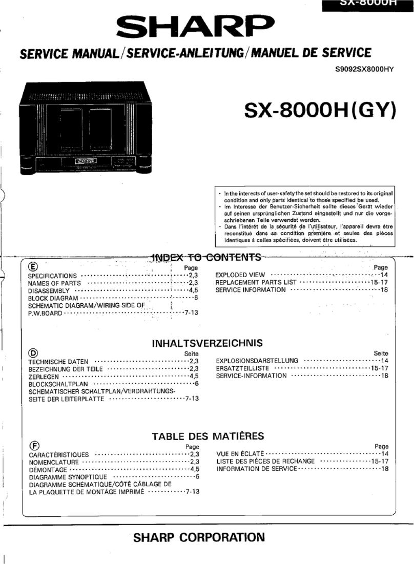
Sharp SM-510H User manual

SHARP
Service
Manual
MODEL
SM-510H
INDEX
TO
CONTENTS
CHASSIS
REMOVAL
.......
0...
c
cece
eee
ees
2
EQUIVALENT
CIRCUIT
OF
INTEGRATED
CIRCUIT
.
8
BLOCK
DIAGRAM
2...
6...
ees
2
TROUBLE
SHOOTING
..............
0000
aes
9~
12
CIRCUIT
DESCRIPTION
...........-.
00000
3~6
PRE/MAIN
AMP
BOARD
WIRING
SIDE.........
13,14
VOLTAGE
SELECTOR
PLUG
&
SCHEMATIC
DIAGRAM
........
0.00.
eve
eee
15,16
FUSE
REPLACEMENT
.........
00.0
e
eee
eens
7
PARTS
LIST
inn
taw
ices
hu
Ganenintiie
Raveena
ates
17
~
22
POWER
TRANSISTOR
REPLACEMENT
..........
7
SPECIFICATIONS
Circuit;
All
silicon
transistor
pre/main
amplifier
with
OTL,
ITL
&
OCL
circuit
Power
source;
110/220/240V,
50/60Hz
Semiconductors;
9-transistor,
6-IC
(Integrated
circuit),
6-diode
Dimensions;
360(W)
x
130(H)
x
240
(D)mm
Weight;
5kg
Music
power
output;
2
x
30W
Both
channels
drive
at
1%
T.H.D.
(Total
Harmonic
Distortion),
4
ohm
Continuous
power
output;
2
x
13W
Both
channels
drive
at
1%
T.H.D.
4
ohm
Distortion;
0.15%
at
1W
Frequency
response;
30Hz—20,000Hz
+
1.5dB
Output
impedance;
4
or
8
ohm
Input
sensitivity
(at
13W
output);
PHONO-MAG:
3mV
PHONO-CERAMIC:160mV
AUX,TUNER:
160mV
TAPE:
160mV
Output
level;
TAPE
REC
OUTPUT:
30mV
SHARP
CORPORATION
OSAKA,
JAPAN

CHASSIS
REMOVAL
w
the
up-and-down
sides
bolts
(3)
on
th
|
UUUUUUUL
nnnnann
YUUUUUUUY
o@fSdvAaAy
nect
the
power
plug
of
the
se
nscrew
the
9
bolts
(1)
on
eee
Fg
°Q
Fig.
1
Chassis
Removal
Fig.
2
Block
Diagram

CIRCUIT
DESCRIPTION
This
is
a
highly
1C-ed
pre-main-amplifier
with
OCL
(Output
Capacitor
Less)
amplifier.
It
consists
of
equalizer
amplifier,
tone
control
unit,
main
amplifier
protection
circuit
and
power
supplier.
Followings
are
explanation
about
each
circuitry
and
its
operation.
1.
MAIN
AMPLIFIER
The
main
amplifier
consists
of
driver
IC
and
power
transistor.
The
driver
IC
is
specifically
designed
to
drive
the
power
transistor
and
the
internal
current
limitter
to
protect
the
output
power
transistor
from
accidental
shortcircuit
or
overload,
being
workable
on
either
single
or
split
power
supply.
The
equivalent
circuit
of
this
IC
is
as
shown
in
Fig.
3.
Fig.
3
Equivalent
Circuit
Fig.
4
Principle
Circuit
Ee
Tae

Referring
to
the
equivalent
circuit
in
Fig.
3
and
the
principle
circuit
in
Fig.
4,
we
explain
the
operation
of
the
circuit.
The
input
signal
is
applied
in
between
K313
and
earth
and
then
to
the
PIN
8
via
the
C301.
The
Q1
and
Q2?2
serve
as
differential
amplifier,
which
works
to
connect
the
signal
given
with
the
single
power
supply
(from
the
previous
stage)
with
the
amplifier
operated
on
the
split
power
supply.
The
Q3,
D1
and
D2
form
constant
voltage
circuit.
The
signal,
which
is
differencial-amplified
in
the
Q1,
is
supplied
to
the
base
of
Q4
via
the
PIN7
.
The
D6
~
D8,
connected
to
the
collector
of
Q4,
give
an
appropriate
bias
to
the
next
stage
and
also
supply
thereto
the
balanced
signal
with
the
earth
positioned
at
the
center.
The
Q11
is
NPN
transistor.
These
PNP
and
NPN
transistors
form
complementary
circuit.
Therefore,
the
upper
half
of
waveform
is
amplified
at
the
Q401
via
the
PIN
2
and
the
lower
half
amplified
at
the
Q403
via
the
PIN
13
,
which
then
appear
in
the
K313
as
output
waveform.
Since
the
DC
voltage
of
K313
is
of
OV,
it
is
not
needed
to
use
the
coupling
capacitor
conventionally
employed
in
the
SEPP
type
amplifier.
(The
name
of
OCL
is
derived
from
this
fact.)
The
Q15
works
to
filter
the
ripple
of
+B
if
the
capacitor
is
inserted
to
the
PIN
4
.
The
Q11
and
Q13
form
current
limitter.
If
an
abnormal
current
runs
in
the
Q401
and
Q403,
DC
voltage
increases
in
the
R313
and
R315
and
reaches
the
base
of
Q10
and
Q13
via
the
PIN
1
and
12
,
causing
the
signal
to
be
grounded.
The
minimum
current
required
for
operating
this
protection
circuit
can
be
adjusted
by
the
values
of
the
R309
and
R311.
The
R305
is
a
resistor
to
determine
the
negative
feedback
amount.
With
the
R305
lessened,
the
nagative
feedback
amount
decreases,
thus
increasing
the
gain
of
the
maplifier.
To
the
PIN
6
and
7
is
connected
the
capacitor
for
preventing
the
oscillation.
The
OCL
amplifier
is
an
ideal
amplifier.
from
the
following
points;
Its
low
frequency
response
characteristic
is
superior
in
particular
because
of
the
absence
of
the
coupling
capacitor,
and
flat
reproduction
is
assured
up
to
as
low
as
10Hz
in
the
case
of
main
amplifier
alone.
In
addition,
negative
feedback
is
sufficiently
applied
due
to
the
IC
driver
to
remarkably
lessen
the
distortion.
2.
EQUALIZER
AMPLIFIER
OUTPUT
!
Fig.
5
Equivalent
Circuit
Fig.
6
Equalizer
Amplifier
Explained
here
is
the
operation
of
this
circuit.
The
internal
equivalent
circuit
of
the
IC201
is
of
directcoupled
3-stage
amplifier.
The
first
stage
Q1
serves
as
grounded
emitter
circuit
and
the
input
signal,
coming
via
the
K202,
is
amplified
at
the
base
of
QI
and
then
appears
in
the
collector.
In
order
to
increase
the
collector
load
of
Qi
the
second
stage
Q2
and
third
stage
Q3
are
made
an
equivalent
circuit
with
Darlington
connection,
thus
the
input
impedance
at
the
second
stage
is
increased.
The
last
stage
Q3
serves
as
grounded
emitter
circuit
and
obtains
the
output
from
the
collector.
The
bias
is
supplied
from
the
emitter
(PIN
5)
of
Q3
to
the
base
(PIN
2)
of
QI
via
the
R205.
(DC
negative
feedback
type.)
agin,

This
IC
is
developed
for
the
low
frequency
high
gain
amplifier,
of
which
the
withstand
voltage
is
higher
enabling
the
power
supply
voltage
to
increase
and
then
the
dynamic
range
is
significantly
extended.
It
is
also
manufactured
taking
the
advantage
of
PCT
system
(Perfect
Crystal
Device
Technology)
which
lessens
the
noise.
In
addition,
the
gain
of
the
first
stage
is
increased
as
the
load
resistance
of
Q1
is
made
higher
and
also
the
noise
in
the
next
stage
and
on
is
limitted
to
the
minimum.
Therefore,
the
overall
noise
through
the
whole
circuit
is
fully
reduced.
The
negative
feedback
block
connected
between
the
PIN
6
and
3
works
to
determine
the
frequency
characteristic
and
gain
of
this
amplifier.
In
this
circuit
is
employed
the
parallel
CR
circuit
to
obtain
RIAA
curve
characteristic
but
if
the
pure
resistor
is
used
instead
for
this
circuit,
this
equalizer
also
serves
as
flat
amplifier.
3.
TONE
CONTROL
UNIT
The
tone
control
unit
is
consisted
of
level
controller,
tone
control
amplifier
and
tone
controller.
The
level
controller
comprises
the
balance
control
and
volume
control.
As
to
the
balance
control
of
this
set,
MN
type
curve
rotary
variable
resistor
is
employed.
(See
Fig.
7.)
100
E
RIGHT
(M)
~
£
€
:
5
=
x
50
8
8
®@
§
©
=
&
Ld
]
F
|
3
Oe
Of
o
o°
150°
300°
eS
150°
—l|M_
—_—_—e_—OO
Rotation
(degree)
Rotation
(degree)
Fig.
7
Balance/Volume
In
the
tone
control
amplifier
is
applied
the
same
IC
as
that
for
the
equalizer
amplifier
described
in
the
item
3
“EQUALIZER
AMPLIFIER”.
Their
circuits
are
the
same
in
basic
structure
but
in
the
circuit
of
tone
control
amplifier
is
used
pure
resistor
instead
of
the
negative
feedback
block
as
in
Fig.
6
to
assure
a
flat
frequency
response
characteristic.
Since
the
tone
control
circuit
herein
is
the
CR
type
one
which
is
conventionally
employed,
the
explanation
for
it
is
omitted
300°

4.
PROTECTION
CIRCUIT
As
seen
from
the
item(1)
“MAIN
AMPLIFIER”,
the
protection
circuit
incorporated
in
the
1¢301
prevents
the
set
from
being
affected
by
the
overload
signal
due
to
the
shortcircuit
of
speaker
terminal,
but
the
speaker
happens
to
be
burn
out
due
to
the
employment
of
OCL
circuit
with
which
the
DC
current
may
run
directly
into
the
speaker
if
a
big
DC
voltage
is
applied
to
between
the
earth
K323
and
output
terminal
K313
or
K314
in
the
worst
case.
In
an
ordinary
state,
it
scarcely
occurs
that
DC
voltage
is
applied
to
between
the
K323
and
K313
or
K314
because
the
IC-301
or
1C302
incorporates
the
circuit
to
balance
DC.
DC
is
applied
thereto
only
when
the
1C301
(or
IC-302),
Q401
and
Q403
(or
Q402
and
Q404)
are
accidentally
destroyed.
However,
to
further
counteract
the
rare
case
above,
the
protection
circuit
formed
by
the
Q301
~
Q304
and
relay
is
additionally
provided
to
protect
the
speaker.
When
the
plus
DC
voltage
appears
in
between
the
K313
and
K323,
it is
applied
to
the
base
of
Q304
via
the
R329.
As
the
result
the
current
runs
in
the
Q304
and
its
collector
voltage
drops
more
abundantly
than
in
the
case
of
non-signal
because
of
the
R319.
The
Q302
and
Q301
are
PNP
transistors.
The
PNP
transistor
gets
conductive
when
the
base
voltage
becomes
minus
with
respect
to
the
emitter
voltage,
and
therefore
the
current
runs
in
the
Q304
and
also
in
the
Q302,
to
cut
off
the
Q301,
then
the
relay
stops
to
operate.
In
a
normal
condition,
as
soon
as
the
power
switch
is
turned
on,
the
relay
starts
to
operate
to
connect
the
amplifier
with
the
speaker.
In
an
abnormal
condition,
however,
the
relay
is
cut
off
to
protect
the
speaker
from
possible
damage.
When
the
voltage
between
the
speaker
terminals
is
plus,
the
Q303
does
not
function
but
when
it
is
minus,
the
Q303
functions
to
cut
off
the
relay
as
in
the
case
the
voltage
is
plus.
The
R329,
C315
and
C316
form
low
pass
filter
to
prevent
the
relay
being
worked
by
audio
signal.
The
relay
is
the
inductive
one
and
will
generates
reaction
voltage
if
it
is
abruptly
turned
on
or
off.
This
voltage
is
absorbed
by
the
D301,
however.
The
minimum
nubalanced
DC
voltage
to
make
the
relay
operate
is
depended
upon
the
value
of
R319
or
R327.
Not
operate
Fig.
8
Principle
Protection
Circuit

VOLTAGE
SELECTOR
PLUG
&
FUSE
REPLACEMENT
1.
ACLINE
FUSE
When
the
unit
does
not
function
due
to
a
blown
fuse,
remove
the
power
cord
and
replace
the
old
fuse
on
the
fuse
holder
with
a
new
once.
Use
a
1.0A
fuse
for
220V,
240V;
2.0A
fuse
for
110V.
NOTE:
When
replacing
the
fuse,
never
use
a
copper
wire
or
other
fuse
of
improper
capacity.
2.
CIRCUIT
PROTECTION
FUSE
Provied
on
the
chassis
near
the
Power
Transformer.
If
sound
through
speakers
are
cut,
the
protection
fuse
has
been
blown.
Turn
the
power
switch
off
immediately
remove
the
cabinet
by
loosing
the
screws
on
the
side
of
the
set,
and
check
for
a
short
on
the
connections
between
speaker
enclosures
and
amplifier.
If
short
circuited
repair
it
and
replace
the
protection
fuse.(0.5A).
3.
VOLTAGE
CHANGING
Be
sure
to
check
the
pre-set
voltage
before
operating
the
set.
If
the
voltage,
is
different
from
your
local
voltage
according
to
the
voltage
selector
plug
as
follows:
1)
Disconnect
the
AC
power
cord
from
the
outlet
in
order
to
prevent
an
electric
shock.
2)
Remove
the
plug
cover
by
unscrewing
screw
on
it.
(See
Fig.9)
3)
Pull
out
the
selector
plug
cover
and
reinsert
it
with
the
desired
voltage
coming
upward.
(See
Fig.
10)
4)
Replace
the
plug
cover
in
its
original
position.
The
desired
voltage
now
appears
in
the
plug
cover
opening.
(See
Fig.
9)
Figure
9
POWER
TRANSISTOR
REPLACEMENT
The
power
transistors
used
in
the
output
stages
are
matched
pairs.
They
have
been
selected
so
that
they
have
very
similar
current
gain
and
trans-conductance
characteristics.
This
matching
is
necessary
in
order
to
assure
optimum
perfor-
mance,
but
is
such
that
if
a
transistor
fails
in
either
channel,
another
transistor
in
that
channel
must
also
be
replaced.
Transistors
are
supplied
only
in
matched
pairs
for
replacement.
The
transistors
diffuse
a
large
amount
of
heat
which
must
be
carried
off
in
order
to
prevent
damage
to
the
transistors
the
collectors
of
which
are
thermally
connected
to
the
heat
sink
by
means
of
electrical
insulators
to
avoid
grounding.
The
insulator
is
a
very
thin
plastic
film
mounted
between
the
transistor
case
(collector)
and
the
heat
sink.
A
layer
of
silicon
grease
which
is
a
good
conductor
of
heat
is
applied
to
both
sides
of
the
insulator
in
order
to
improve
heat
sink
operation.
When
the
power
transistors
are
replaced
the
spacer
film
must
be
re-installed
and
a
new
layer
of
grease
applied
to
both
sides.
Care
should
be
taken,
lest
conductive
dust
such
as
metal
particles
should
break
through
the
insulator
films.
Q401
and
Q403,Q402
and
Q404
are
matched
pairs.
=
Figure
10
SCREW___
>
(X3P+10S)
TRANSISTOR
eS
<-—
(2SC789©)
SPACER
(AC301)
LUG
(3HW)
SPRING
WASHER
(3SW)
NUT
(X3ND)
Figure
11
POWER
TRANSISTOR
REPLACEMENT
Figure
12
EQUIVALENT
CIRCUIT
OF
INTEGRATED
CIRCUIT

€0vOS
~
LOVOS
‘VLOLMS
ZLZO'LLZO.
2029‘
L029'Z0Z91'L0Z91
wWVYOVIGC
OILVINHOS,,
NI
GalsI94adS
AJDVLIOA
AO
ADNADYSAIG
GOvVOS
‘vOVOS
‘ALOLMS
LINDYID
TOYLNOD
ANOL
‘YA
“lS
Id
NV-4
ud
ONV
JAYIsIIdAIV
NIV
40
SDVLS
HOWS
NOAHO
LELOLOLYS'LOLO
YOLSISNVYL
YIlWVd
HOWA
4O
SADVLIOA
3YVdWO0O
YO
‘ADVLIOA
40
SONADYSAIC
uWNVYOVIG
OILVWHOS.,
NI
GalsIDadS
ADVLIOA
40
AONAOYSAIC
(YVW4Y)
YOLOATAS
ADVLIOA
JHL
AOSHO
ZOEDI'LOEOI
wWVYOVIC
OILVINHOS.,
NI
Gala!d3adS
AJDVLIOA
AO
JDNADYSAIG
ANOHdOW3H
‘W3ALSAS
Ya>VAdS
ZOEDI'LOED!
vOvVO
~
LOvO
Ga9V1d4u
SI
LISV
NOOS
SV
SMO19
4SN4
SH
JI
uWV¥OVIG
SILVNHOS,,NI
GalsdldddS
JDVLIOA
AO
JDNADYAAIC
YAWNYOSSNVYL
SO
ALINNILNOD
SOFHO
LINDYID
A1ddNS
YAMOd
JO
ALINNILNOD
ADSHD
SAILO345G0
SI
LI
‘WHO
0
OL
3S019
HO
WHOO
SI
11
41
YSLLIWS
GNV
¥O19377109
SHL
NFAMLAG
ALINNILNOD
XOSHO
vov0
~
LOvO
VLEO'ELED
LOvL
Q30V1d5u
SI
LI
SV
NOOS
SV
SMO718
ASN4
3H1
Al
LXAN
OL
434544
9LEX
LV
ADVLIOA
CNV
vOED
~
LOED
‘AV1SY
NOAHO
YaNWads
JOV1d3y
YO
GYOO
NayOUs
Hivd3y
1109
4910A
GNV
‘GHOO
YANVAdS
JO
ALINNILNOD
XOSHO
LNIOd
AOSHD
YO
Od
OL
LVHM
“LANSDOS
YO
HOLIMS
NOILONAS
3AIL93440
aid
“dV
YAZITWNOA
AAILOASAAC
LAXADOS
YO
HOLIMS
NOILONNA
JAILOIS3G
HLVd
TWNOIS
JO
LINDYID
LYOHS
YO
N3adO
Y3ALMWs
Addi
dO
LINDYID
LYOHS
YO
NadO
LINDYID
YHAMOd
JAILOAAAG
ADVLIOA
AlddNS
OV
MOT
‘O1
SAILO3AAG
YAlsIIdWV
O1GANV
SAILO3S44AG
1LNdLno
LV
39IAAG
GALYOHS
YO
3AIL94440
YOLSISNVYL
YAMOd
GALYOHS
YO
SAILOASAG
4snja
NMO19
¢c-ONOHd
YO
L-ONOHd
LV
AGOW
Advil
4¥O
YINNL'XNV
LV
Ald
“dNS
90
IWINYON
Ald
“dNS
90
IWNYONSV
GQNNOS
ON
LNd
LINDYID
ATddNS
YAMOd
JAILOAAAG
YAWYOASNVYL
Y4MOd
4O
ONIGNIM
AYWWIYd
NANOS
YsIsIIdWV
YAMOd
AO
LINDYID
AlddNS
YAMOd
GSALYOHS
HOLSISNVYL
YHAMOd
GA.LYOHS
YOLIDVdVO
GALYOHS
YAWYOASNVUL
YAMOd
G4.LYOHS
3Sn4a
NMO18
LOVLNOD
DN
1d
OV
ASOO1
guyoo
ANI1T
YO
HOLIMS
44O0-NO
3AIL035430
|
LANDOS
TIVM
LV
YAMOd
ON
AYyIsIId
NV
OIGNV
SAIL0S445G0
AV144
ALVYAdO
LON
MOD
ADIOA
YO
AHOMLAN
GuYOO
YAyV3AdS
GALYOHS
YO
NANO
ASNVS
A1VaOdd
|
‘NO
SI
dAW1
LO1d
4AO
SI
dNV1
LOTId
‘Y4MOd
OV
ON
60E>
YO
vOE
“>
LV
GaL94140
9G
60>
YO
vOEX
LV
TVINYON
MO
YAMOd
OV
WOLdWAS
dAV1
LONd
HV
AGOW
ANO
LV
GNNOS
ON
avad
TANNVH9-SNO
SACOW
11V
GNNOS
VAM
SAGOW
11V
GQNNOS
ON
WOLdWAS
(L)
SHQOW
IWNOILVHY3d0
T1V
—10—

‘8029
~
GOZO
OLZH
~
ZOTY'ZLLU'LLLY
HOLIMS
HOLINOW
ddV1
40
LOVLNOD
3SOO071
Y30HOOSY
Adv
IOW1dSY
JAAILO343G
Y3CHOOSY
AdVL
YAISIIdINV
|
|
AW
1d
Sd
VL
‘038
ZLZ7D'LLZO'ZOZI‘
LOZO
YOLIOVdV9
JAILOAAAG
918
'QLZU
‘GLZU
YOLSISSY
JAILOASAG
Z0ZOI'LOZOI
YOLSISNVYL
SAILOSA30
«/NVYOVIG
OILVNHOS,,
NI
Ga1s104adS
AJDVLIOA
40
JONADYSAIG
Y3Z11VWNOA
AAILOAAAG
GQNNOS
>AVAM
YO
YSIS
IdWV
|
GNNOS
ON
OL
STVNIWYSL
NSSML39
Yivd3y
GNV
ANOAHO
LINDYID
GVOT
NANOS
TWNIWY
SL
NIG
YO
MOWEF
Nid
IWNIWYSAL
gOvOS~
LOvOS
LNdNI
40
SLOVLNOD
3SO07
HOLIMS
GLOLMS'VLOVMS
4¥0193474S
NO
LOWLNOOD
3SO0071
MOAHD
OL
SADYNOS
LNdNI
ADW1d4y
AAILO343d0
JDYNOS
LNdNI
ASNVO
319VdOud
WOLdNWAS
|
WO1LdWAS
(938
3dVL
ONOHd)
STVNIWYSL
LNdLNO
YO
LAdNI
HLIM
ONISN
LNIOd
NOAHD
YO
OG
OL
LVHM
LINDYID
YO
LOLYA
AAILOAIS3SG
TOYLNOD
JDNV1VE
>YOM
LON
S300
S300
1OY¥LNOO
LINDYID
YO
VOLYA
AAILDSAIG
TOYLNOS
319441
LINDYID
YO
ECOLYA
JAILDSI43SG
TOYLNOO
SSV4
T1V
LV
YOM
LON
S400
HOLIMS
YNOLNOD
SSANGNO1
LINDYID
YO
HOLIMS
EOVMS
YNOLNOD
SANGNOT
JAIL944350
COvVMS
TWINYON
NOILNTOASY
Y3AO
NI
SI
1OYLNOOD
AWN
TOA
VOLYA
~
LOLYA
YAAVAdS
JAILOIAIG
STOYLNOD
ASION
YA
WAdS
JOV1d45y
YOLSISAY
ATEVIYVA
AAILI3S30
Yay
VAdS
4O
NYOO WOYS
dil
LNVNOSSY
AVMV
daa)
‘NIVDV
SM4HYDS
XI
Yay
VsadS
SACOW
LSNd
YO
LNANOdWOO
YaIWAdS
4O
LOVLNOO
YANNI
LNVNOS3Y
11v
NI
ASION
SISSVHO
OL
HOVE
“ANOHdOVW3H
A11V194dS4
‘SISSVHO
OL
LINA
OIGNV
YSHLO
YO
Y3ISINdNV
YAMOd
JO
HLYW]
4O
LINDYID
LYOHS
‘
SISSVHO
OL
LOvr
SISSVH9
OL
LINN
AV
SISSWHO
“ONV
YSISIIdINV-3ud
NSSML39
NOIL
“-Q4NNOO
GNNOYD
JO
LINDYID
NAdO
SISSVHO
O1
602>
YSlsIIdNVAud
AO
LINDYID
ATddNS
YAMOd
NI
ATddly
OZEO'6LED'PLED'ELED
YALU
A1ddi¥
JAILOIAIG
AODYNOS
Od
NI
AlddlY
6CLO'LELO'8Z19
4O
145A41
HOIH
HAL
Addy
AAILO3S3d
SAIGON
T1V
NI
WOAH
LINYIOD
WOVEGsss
AAILVOAN
NI
SLYOHS
YO
N3dO
ZOEDILOEDI'ZOZOI'LOZOI'ZOLON
LOLI
OI
VAM
YO
ONIDV
GALYOLSIC
SI
YAHLO
‘XO
SI
TANNVHO
JNO
LINDYID
AONANOAYS
OIGNV
AAILO3435q0
LINDYID
YAMOd
4O
ADVLIOA
LN3IDI4SNSNI
Q3ldloAadS
SV
LON
SADVLIOA
NOILVYadO
4O
YdIVaAdS
AO
YAdWVG
+O
GNV
SACOW
11V
NI
Ya>IWAdS
OW
1d4y
YO
3NOO
“1109
SDIOA
SAILO345q0
YSa>IVAdS
OV
1d4y
NOILYOLSIG
LNIOd
MOSHO
YO OG OL
LVHM
ASNVO
3A1EsVEOud
WOLdNAS
WOLdWAS
|
(Z)SAGOW
TWNOILVY3d0
11V
~12—
a

s0402
$0403 $0404
$0405
SW405
c402
Reo
write
R410
$040!
$0406
S0407
R40
R408
R401
5
c4ol
R409
AC
110/220
240V,
SOHz
YELLOW
SHAR
C3I6
R327
315
26
sirmransnsncscenceel())
>)
i
eS
eee
rare
Figure
13
PRE/MAIN
AMP
BOARD
WIRING
SIDE
=
13—
—14—

So40l
2
IClOl
,
Iclo2
PRE
-
AMP
TA-7122P
RIO7
330K
Ri29
33K
TUNER S0402
AUX
$0403
PHONO2
SO0404
SWIOIA_
MAIN
AMP_
IC301,1IC302
TH-7IIOP
Q401~
Q404,
2SC789LB
(0)
+26V
C307
27P
pea
R224
I8KJ
Po
3f
°
f
O
be
PHONO!
SO|405
2
SZO™N
SW405B
3/0
PN,
SW405A
ier
a
Dy
raga
|
lOOKU
|OOKU
R412
c402
c40l
1.8Ku
470P
470P
R4il
RIO8
(.8KJ
BALANCE
VOLUME
330K
ed
ees
t
R2i5
ik
3iv
(7)
K204
9.5V,
c2il
I6vi0
R2li
8.2KU
3
ell
=
=
c2i5
1O/16V
NOTE
1.
ALL
RESISTORS
ARE
SHOWN
IN
OHMS,
tlO%
SWiloiB
EQUALIZER
AMP
R225
2.2KJ
213
22K
c2ié
lOs16V
Ic201,
C202
TA-7122P
=15=
WH
Ri'2
B.zKJ
iH
+
K206
K
=
1000,
M
=
10&
.
ALL
CAPACITORS
ARE
SHOWN
IN
FADS.
P
=
MMF
.
VOLTAGE
READING
ARE
MEASURED
WITH
VTVM,
UNDER
NO
SIGNAL.
'
R123
10K
BASS
TRE
BLE!
KI20
t
T
a,
K3I7
cize
J
K320
1¢120
Riza,
7
022
18
10K
BK
RI048
VRIO3B
6.8K
v
100KA
one
'
C}
k3i8
Qiol
28C734
(Y)
F402
SW401A
S0708
T401
af
K301
aq)
i):
{}
R309
°°”
1k303
270
ees
R313
AT
loop
IW
SW30I1A
K304
SO-406
SPEAKER
OUT
(L)
330
6.8K
Ri329
6.8K
c318
SWITCHES
ARE
SHOWN
UNDERLINED
POSITION.
AC
II10/
;
YEL
220/240V
|
,
NO.
FUNCTION
POSITION
|
50
Hz
\
ORANGE
SWIOl
|
FUNCTION
AUX
-
PHONO2
-
PHONO!
-
TUNER]
‘O-
sw30l
|
RELAY
ON
-
OFF
|
RED
swao1
|
Power
ON
-
OFF
|
;SW40iB
F401
ov
SW402
|
TAPE
MONITOR
ON-
OFF
=<
4
BLK
+—
1
ote
_
©
Sw403
|
LOUDNESS
ON
-
OFF
i
5.7V
sw404
|
MODE
STEREO
-
MONO
PL:
401
F403
awe
—
SW405
|
CARTRIDE
SELECTOR]
MAG
-
CERAMIC
eV'SomA
bilo
ov
PURPLE
.
PARTS
NUMBERS
Pare
1lol~
199
PRE
-
AMPLIFIRES
4
IC301,
1C
302
IClOl,
IClO2,
IC201,
IC202
¢
‘BOTTOM
VIEW)
201~
299
EQUALIZER
AMPLIFIES
R
301
~~
399
POWER
SUPPLY
&
MAIN
AMP
&
401
~
499
OTHERS
&:
ores
2s
4
Se
SE
Figure
14
SCHEMATIC
DIAGRAM
el
POWER
SUPPLY
~
SR301~304
vo3B
—16—
35V
2200
-
26V
Q301,Q302
2SA56I
(Y)
SM-5IOH-([
|
|
Q303,0304
28734
(Y)
HEADPHONES
J40l
SO-407
SPEAKER
OUT
(R)

=—[/=
=-[8-

|
REF.
NO.
|
NEW
PART
NO.
OLD
PART
NO.
CAPACITORS
C101,C102
C103,C104
C105
,C106
C107,C108
C109,C110
C111,C112
C113,C114
C115,C116
C117,C118
C119,C120
C121,C122
C123,C124
C126
C128
C129
C131,C132
C133,C134
C137
C201,C202
C203,C204
C205
,C206
C207,C208
C209,C210
C211,C212
C213,C214
C215,C216
C301,C302
C303,C304
C305
C306
C307
C308
C309,C310
C311,C312
C313,C314
C315
C316
C317,C318
C319,C320
C321,C322
C323
VCQYKU1HM152K
VCKYPU1INB154M
VCAAKU1CA474M
VCCSPU1HL8ROC
VCCSPU1HL271K
VCEAAU1EW335R
VCAAKU1CA334M
VCEAAU1AW476Q
VCQY
KU
1HM223K
VCQYKU1HM184K
VCQYKU1HM223K
VCQYKU1HM152K
VCKYPU2HB103P
VCEAAU1HW477Q
VCEAAU1HW106Q
VCEAAU1LHW106Q
VCEAAULHW105R
VCEAAU1HW107Q
VCAAKU1CA334M
VCCSPU1HL470K
VCQYKU1HM103K
VCQYKU1HM392K
VCEAAU1AW107Q
VCEAAUI1CW106Q
VCEAAU
1HW476Q
VCEAAU1HW105R
VCAAKUI1CA105M
VCEAAU1HW106Q
VCEAAU1CW476Q
VCCSPU1HL270K
VCCSPUIHL101K
VCQYKU1HM104K
VCEAAU1VW228Q
VCEAAU
1CW227Q
VCQYKU1HM
104K
VCEAAU
1LEW336Q
VCQYKU1HM154K
VCEAAU1HW105R
“HOW
TO
ORDER
REPLACEMENT
PARTS”
To
have
your
order
filled
promptly
and
correctly,
please
furnish
the
following
informations.
1.
MODEL
NUMBER
3.
NEW
PART
NO.
ML-5-156K
D-1.2-154M
AD1.6-474M
D-5-809C
D-5-277K
CU2.5-333R
AD1.6-334M
CU-1472Q
ML-5-225K
ML-5-184K
ML-5-225K
ML-5-156K
D-50-105P
CU-5-471Q
CU-5-102Q
CU-5-102Q
CU-5-103R
CU-5-101Q
AD2.5-103M
D-5-478K
ML-5-105K
ML-5-396K
CU-1-101Q
CU1.6-102Q
CU-5-472Q
CU-5-103R
AD1.6-103M
CU-5-102Q
CU1.6-472Q
D-5-278K
D-5-107K
ML-5-104K
CU3.5-220Q
CU1.6-221Q
ML-5-104K
CU2.5-332Q
ML-5-154K
CU-5-103R
2.
REF.
NO.
4.
DESCRIPTION
DESCRIPTION
.0015MFD,
S0V
+10%,
Mylar
.15MFD,
12V,
+20%,
Discap
-4TMED,
16V,
+20%,
Electrolytic
8PF,
50V,
+0.25PF,
Discap
270PF,
50V,
+10%,
Discap
3.3MFD,
25V,
+150%,
—
10%,
Electrolytic
.33MFD,
16V,
+20%,
Electrolytic
47MFD,
10V,
+100%,
—
10%,
Electrolytic
,022MFD,
50V,
+10%,
Mylar
.18MFD,
SOV,
+10%,
Mylar
.022MFD,
50V,
+10%,
Mylar
.0O1SMFD,
S50V,
+10%,
Mylar
.OIMFD,
S500V,
+100%,
—0%,
Discap
470MED,
S50V,
+100%,
—10%,
Electrolytic
10MFD,
SOV,
+100%,
—10%,
Electrolytic
10MFD,
50V,
+100%,
—10%,
Electrolytic
IMFD,
SOV,
+150%,
~10%,
Electrolytic
100MFD,
S50V,
+100%,
—10%,
Electrolytic
1MEFD,
25V,
+20%,
Electrolytic
47PF,
S50V,
+10%,
Discap
.OIMFD,
50V,
+10%,
Mylar
.0039MFD,
50V,
+10%,
Mylar
100MFD,
10V,
+100%,
—10%,
Electrolytic
10MFD,
16V,
+100%,
—10%,
Electrolytic
47MFD,
50V,
+100%,
—10%,
Electrolytic
IMFD,
SOV,
+150%,
—
10%,
Electrolytic
1MFD,
16V,
+20%,
Electrolytic
10MFD,
50V,
+100%,
—
10%,
Electrolytic
47MFD,
16V,
+100%,
—
10%,
Electrolytic
27PF,
50V,
+10%,
Discap
100PF,
50V,
+10%,
Discap
-IMFD,
S50V,
+10%,
Mylar
2200MFD,
35V,
+100%,
—
10%,
Electrolytic
220MFD,
16V,
+100%,
—
10%,
Electrolytic
.IMFD,
50V,
+10%,
Mylar
33MFD,
25V,
+100%,
—
10%,
Electrolytic
.1S5MFD,
50V,
+10%,
Mylar
1MFD,
SOV,
+150%,
—
10%,
Electrolytic
—19—
MODEL
SM-510H

SHARP
REF.
NO,
NEW
PART
NO.
OLD
PART
NO.
DESCRIPTION
ae
aa
C325,C326
C401,C402
C503
ON,
R105,R106
R107,R108
R109,R110
R111,R112
R113,R114
R115,R116
R117,R118
R119,R120
R123,R124
R126
R127
ae
R130
R131,R132
R133,R134
R135,R136
R201,R202
R203,R204
R205,R206
R207,R208
R209,R210
R211,R212
R213,R214
R215,R216
nea
R219,R220
R221,R222,
R223,R224
R225,R226
R227,R228
R301,R302
R305,R306
R307,R308
eee
R311,R312
R313,R314,
ieee
R317,R318
R319
R320
R321
R322
R323
R324
R325
R326
R327
R329,R330
R331,R332
R401,R402
R403,R404
VCCSPU1HL271K
VCCSPU1HL471K
VCPOAT3AC403M
D-5-277K
D-5-477K
OL-1K-405M
RESISTORS
270PF,
50V,
+10%,
Discap
470PF,
50V,
+10%,
Discap
-O4MFD,
1000V,
+20%,
Oil
(Unless
otherwise
specified
resistors
are
4W,
+10%,
Carbon
type.)
VRD-ST2EY222J
VRD-ST2EY
334K
VRDST2EY683K
VRD-ST2EY123J
VRD-ST2EY
183K
VRD-ST2EY682K
VRD-SU2EY394K
VRD-SU2EY222K
VRD-ST2EY
103K
VRD-ST2EY331K
VRD-ST2EY151K
VRD-ST2EY
333K
VRDST2EY222J
VRD-SU2EY683K
VRD-ST2EY
123K
VRD-ST2EY
1025
VRD-ST2EY
334K
VRD-ST2EY104K
VRD-ST2EY
184]
VRDST2EY
183J
VRDST2EY822J
VRDST2EY223K
VRD-ST2EY
102K
VRDST2EY
3335
VRD-ST2EY
183J
VRDST2EY222J
VRDST2EY473K
VRD-ST2EY271K
VRD-ST2EY271J
VRD-ST2EY
154K
VRDST2EY271K
VRF-GV3ABR47K
VRC-MT2HG100K
VRDST2EY
183K
VRC-MT2HG390K
VRD-ST2EY
153K
VRD-ST2EY683K
VRD-ST2EY
153K
VRC-MT2HG392K
VRC-MT2HG471K
VRDST2EY
333K
VRDST2EY332K
VRD-ST2EY682K
VRDST2EY221K
VRD-ST2EY224J
VRD-ST2EY683J
1/4SA2.2KJ
1/4SA330KK
1/4SU-68KK
1/4SA-12KJ
1/4SA-18KK
1/4SA6.8KK
1/4SU390KK
1/4SU2.2KK
1/4SA-10KK
1/4SA-330K
1/4SA-150K
1/4SA-33KK
1/4SA2.2KJ
1/4SU-68KK
1/4SA-12KK
1/4SA-1KJ
1/4SA330KK
1/4SA100KK
1/4SA180KJ
1/4SA-18KJ
1/4SA8.2KJ
1/4SA22KK
1/4SA-1KK
1/4SA-33KJ
1/4SA-18KJ
1/4SA2.2KJ
1/4SA47KK
1/4SA-270K
1/4SA-270]
1/4SA150KK
1/4SA-270K
1/2M-10K
1/4SA-18KK
1/2M-39K
1/4SA-15KK
1/4SA-68KK
1/4SA-15KK
1/2M-3.9KK
1/2M-470K
1/4SA-33KK
1/4SA3.3KK
1/4SA6.8KK
1/4SA-220K
1/4SA220KJ
1/4SA-68KJ
2.2K
ohm,
“W,
+5%,
Carbon
330K
ohm
68K
ohm
12K
ohm,
“’W,
+5%,
Carbon
18K
ohm
6.8K
ohm
390K
ohm
2.2K
ohm,
%4W,
+5%,
Carbon
10K
ohm
330
ohm
150
ohm
33K
ohm
2.2K
ohm
68K
ohm
12K
ohm
1K
ohm,
%4W,
+5%,
Carbon
330K
ohm
100K
ohm
180K
ohm,
%W,
+5%,
Carbon
18K
ohm,
%4W,
+5%,
Carbon
8.2K
ohm,
%W,
+5%,
Carbon
22K
ohm
1K
ohm
33K
ohm,
4W,
+5%,
Carbon
18K
ohm,
“W,
+5%,
Carbon
2.2K
ohm,
%W,
+5%,
Carbon
47K
ohm
270
ohm
270
ohm,
“4W,
+5%,
Carbon
150K
ohm
270
ohm
47
ohm,
1W,
+10%,
Cement
10
ohm,
4W,
+10%,
Carbon
18K
ohm
39
ohm,
“’W,
+10%,
Carbon
15K
ohm
68K
ohm
15K
ohm
3.9K
ohm,
“’W,
+10%,
Carbon
470
ohm,
4W,
+10%,
Carbon
33K
ohm
3.3K
ohm
6.8K
ohm
220
ohm
220K
ohm,
1/4W,
+5%,
Carbon
68K
ohm,
1/4W,
+5%,
Carbon
—20—

MODEL
SM-510H
|
REF.NO.
NEW
PART
NO.
OLD
PART
NO.
DESCRIPTION
an
RESISTORS
R405,R406
VRDST2EY193J
1/4SA-19KJ
R407,R408
VRD-ST2EY
333J
1/4SA-33KJ
R409,R410
VRD-ST2EY
104]
1/4SA100KJ
R441,R412
VRDST2EY
1223
1/4SA1.2KJ
R413,R414
VRC-MT2HG221K
1/2M-220K
19K
ohm,
1/4W,
+5%,
Carbon
33K
ohm,
1/4W,
45%,
Carbon
100K
ohm,
1/4W,
+5%,
Carbon
1.2K
ohm,
1/4W,
+5%,
Carbon
220
ohm,
1/2W,
+10%,
Carbon
CONTROLS
RVR-Z0037AGZZ
RVR-A0065AGZZ
RVR-A0033AGZZ
RVR-A0033AGZZ
Q101
VS28C734-Y/-1
Q301
VS2SA561-Y/-1
Q302
VS2SA561-Y/-1
Q303
VS28C734-Y/-1
Q304
VS2SC734-Y/-1
Q401,Q402,
9403,0404
}
VS2SC789LBO-1
1C101,1C
102
RH-IX0002SGZZ
1C201,1C202
RH-IX0002SGZZ
1C301,1C302
RH-IX0423AGZZ
D301
VHD1S2076//-1
SR101
VHDIS1941//-1
aac
ey
$R303,SR304
RH-DX0033AGZZ
$0401
QSOCZ0022AGZZ
$0402
QSOCZ0022AGZZ
$0403
QSOCZ0022AGZZ
$0404
QSOCZ0022AGZZ
$0405
QSOCZ0022AGZZ
$0406
QSOCIJ0203SEZZ
$0407
QSOCIJ0203SEZZ
SWwi01
QSW-R0064AGZZ
SW301
Not
available
SWw401
QSW-P0012AGZZ
Sw402
SW403
SWw404
SW405
QSW-S0035AGSA
QFS-A202AAGNI
QFS-D102AAGNI
QSW-P0043AGZZ
F401
F402
QFS-D501AAGNI
F403
QFS-D501AAGNI
$0408
QSOCE0301AGZZ
J401
QJAKIN0N2ZAGZZ
RELAY
301
Benner
RRLYZ0010AGZZ
T401
RTRNP0273AGZZ
PL401
PLMPM0018AG00
LANGRO294AGZZ
LANGRO289AGZZ
PGUMM002SAG09
LANGQO308AGFT
SEMICONDUCTORS
2SC734Y
2SA561Y
2SAS61Y
2S8C734Y
2SC734Y
2SC789LBO
1S2076
181941
VO3B
MISCELLANEOUS
SO-971
S0-971
$0-971
SO-971
SO-971
$0-035
S0-035
X6S-85SEV
58-69
FUSE-2.0S
FUSE-1.0S
FUSE-0.58
FUSE-0.5S
80-037
PL-2515UL
i=
100K
ohm,
BALANCE
100K
ohm,
VOLUME
100K
ohm,
BASS
100K
ohm,
TREBLE
Transistor,
Ripple
Filter
Transistor,
Protection
Circuit
Transistor,
Protection
Circuit
Transistor,
Protection
Circuit
Transistor,
Protection
Circuit
Transistor,
Power
Amp
Integrated
Circuit,
PreeAmp
Integrated
Circuit,
Equalizer
Integrated
Circuit,
Driver
Amp
Diode,
Surge
Protection
Rectifier
Rectifier
Socket,
TAPE
Socket,
TUNER
Socket,
AUX
Socket,
PHONO-2
Socket,
PHONO-1
Socket,
Speaker
LEFT
Socket,
Speaker
RIGHT
Switch,
Function
Switch,
Parts
of
Relay
Switch,
POWER
Switch,
TAPE
MONITOR
Switch,
LOUDNESS
Switch,
MODE
Switch,
CARTRIDGE
SELECTOR
Fuse,
2.0AT
(110V)
Fuse,
1.0AT
(220/240V)
Fuse,
0.5A
Fuse,
0.5A
Voltage
Selector
Jack,
HEADPHONES
Relay,
Protection
Circuit
Transformer,
Power
Pilot
Lamp
Bracket,
Volume
Control
Bracket,
Switches
Holder,
Rubber,
Pilot
Lamp
Bracket,
Terminal

MODEL
$M-510H
SHARP
|
REF.NO.
|
NEW
PART
NO.
OLD
PART
NO.
DESCRIPTION
a
(ae
QFSHZ0004AGZZ
FH-949
QLUGLOS01SEZZ
LG-973
QTANN9007AGZZ
XT-115
LX-LZ0001AGZZ
3TOK-PB
LANGT0063AGZZ
HON-A-3779
PRDARO049AGFW
PSPAZ9002AGZZ
AC221
PSPAZ9N06AGZZ
AC301
QACCZ0006AG00
ACC-297
QACCB0002AG09
ACC-331BS
QACCS0004AG00
ACC-325SEV
QPLGA0205AGZZ
PG-439
QACCV0001AGZZ
QFSHC200
1SEZZ
FH-127
LCHSM0139AGZZ
PSPANO004A
F09
SPACER9
11B
PSPAI0017AF00
SPAC-4062D
LX-NZ0013AGFN
9TOK-NK
LBSHC0002AGZZ
5P-4
LBSHC0007AGZZ
4P-4
QLUGL0426AGZZ
LG-462Z
PSPAI0052AGZZ
K-SPACER
JKNBP0012AGSB
8K-606
PSPASO01LOAGZZ
HDECQO00SCESA
PL-DEC-P
PSPAS0008AGZZ
K-SPAC0090
HPNLC3149AGSA
JKNBNO127AGSA
JKNBNO110AGSA
8K-596
GCAB-0063AGSA
X2CAB-0006
QPLGS0504AGZZ
PG-453
GCOVH3059AGFT
SO-COV0006
Fuse
Holder,
F401
Lug
Terminal,
5
Pin
Terminal,
Ground
Rivet,
Socket
Retaining
Bracket,
Heatsink
Heatsink
Spacer,
Insulator
Washer,
Insulator
AC
Cord,
3
para
(Without
Plug)
AC
Cord,
2
para
(Without
Plug)
AC
Cord,
Black,
2
Para
Plug,
AC
Cord
(2
Para,
Black)
AC
Cord,
2
Para
(With
Plug)
Fuse
Holder,
F402/F403
Mounting
Plate,
P.W.B.
Spacer,
Headphone
Jack
Washer,
Headphone
Jack
Nut,
Headphone
Jack
Bush,
3
Para
Cord
Bush,
2
Para
Cord
Lug
Terminal,
4
Pin,
2
Ground
Spacer,
Power
Switch
Knob
Knob,
POWER/MODE/LOUDNESS/
TAPE
MONITOR
Spacer,
Push
Switch
Decoration,
Pilot
Lamp
Spacer,
Power
Switch
Knob
Panel,
Controls
Knob,
VOLUME/BALANCE/
BASS/TREBLE
Knob,
Input
Selector
Cabinet
Plug,
Short
Bracket,
Socket
Cover
A2708-2.3MH
Printed
in
Japan.
Table of contents
Other Sharp Amplifier manuals

Sharp
Sharp SD-SG11 User manual

Sharp
Sharp SM-SX100 User manual

Sharp
Sharp SX-8000H User manual

Sharp
Sharp SM-5100H User manual

Sharp
Sharp SM-207H User manual

Sharp
Sharp SM-A75H(BK) User manual
Sharp
Sharp SM-SX1 User manual

Sharp
Sharp SM-SX1 User manual

Sharp
Sharp SX-8000HGY User manual
Sharp
Sharp SM-307H User manual