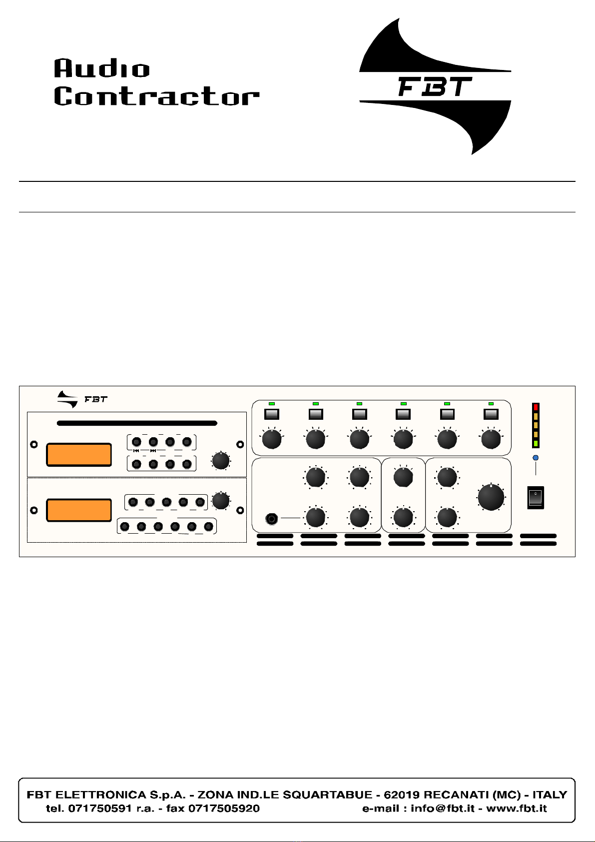
Fbt Audio Contractor MMA 6120-TCD/MP3 User manual
ZONINGAMPLIFIER
ZONINGAMPLIFIER
MMA6120-TCD/MP3
CD/MP3
FM/AMTUNER
VOLUME
VOLUME
PREV NEXT PAUSE EJECT
PLAY STOP
REPEAT FOLDER PRG PWR
FUNCTION
BAND DOWN UP SCAN ME
MEMORY
M1 M2 M3 M4 M5 SHIFT
0 10
0 10
ZONE1 ZONE2 ZONE3 ZONE4 ZONE5 ZONE6
-15
-12
-9 -6
-3
0dB -15
-12
-9 -6
-3
0dB -15
-12
-9 -6
-3
0dB -15
-12
-9 -6
-3
0dB -15
-12
-9 -6
-3
0dB -15
-12
-9 -6
-3
0dB
MIC3 MIC4
MIC1 MIC2
0 10 0 10
0 100 10
TUNERCD/MP3
AUX OFF
LINESELECT
LINE
0 10
+10-10
+10-10
BASS
0
0
TREBLE
MASTERVOLUME
0 10
POWER
0dB
-6
-10
-18
-25
Usermanual
MMA6240-TCD/MP3
MMA6120-TCD/MP3

Allinformationincludedinthisoperatingmanualhavebeenscrupulouslycontrolled;howeverFBTisnotresponsibleforeventual
mistakes.
FBTElettronicaSpAhastherighttoamendproductsandspecificationswithoutnotice.
2
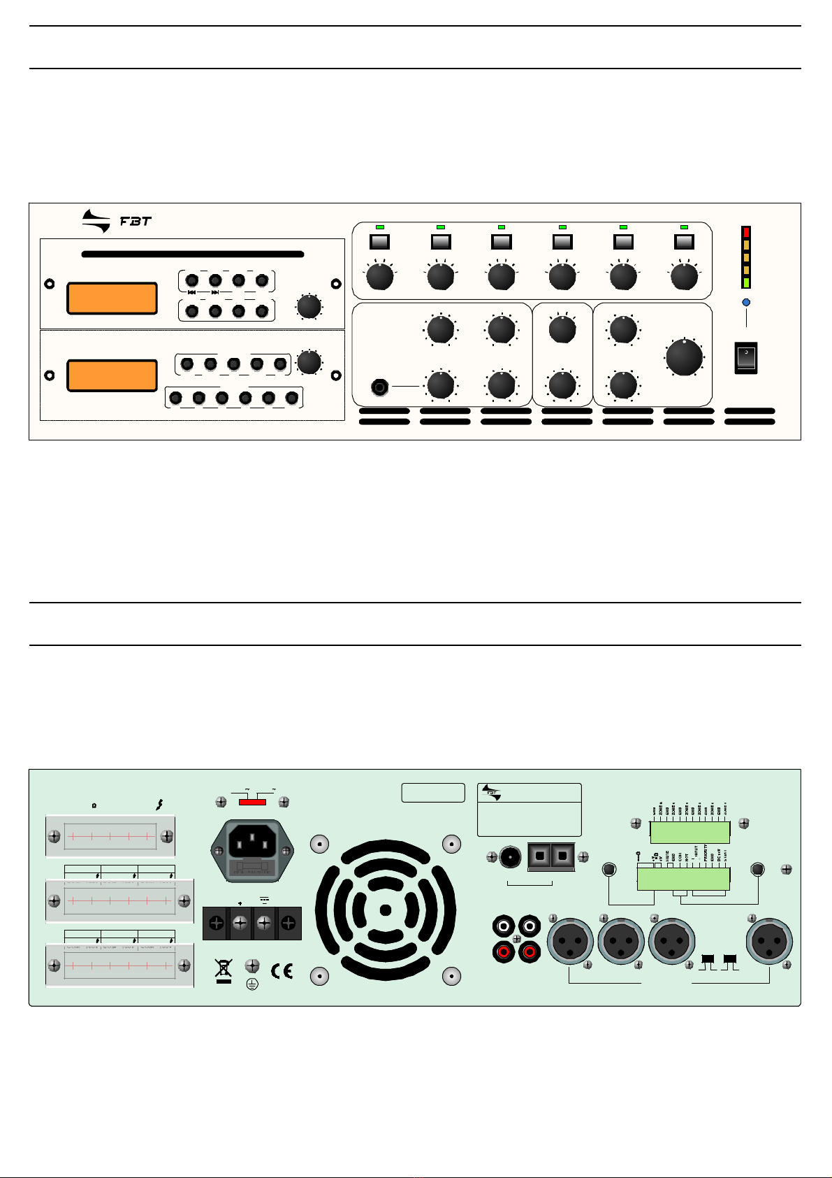
FRONT
REAR
ZONINGAMPLIFIER
MMA6240-TCD/MP3
CD/MP3
FM/AMTUNER
VOLUME
VOLUME
PREV NEXT PAUSE EJECT
PLAY STOP
REPEAT FOLDER PRG PWR
FUNCTION
BAND DOWN UP SCAN ME
MEMORY
M1 M2 M3 M4 M5 SHIFT
0 10
0 10
ZONE1 ZONE2 ZONE3 ZONE4 ZONE5 ZONE6
-15
-12
-9 -6
-3
0dB -15
-12
-9 -6
-3
0dB -15
-12
-9 -6
-3
0dB -15
-12
-9 -6
-3
0dB -15
-12
-9 -6
-3
0dB -15
-12
-9 -6
-3
0dB
MIC3 MIC4
MIC1 MIC2
0 10 0 10
0 100 10
TUNERCD/MP3
AUX OFF
LINESELECT
LINE
0 10
+10-10
+10-10
BASS
0
0
TREBLE
MASTERVOLUME
0 10
POWER
0dB
-6
-10
-18
-25
COM
MMA6240-TCD/MP3
25V 70V 100V8
ZONE4 ZONE5 ZONE6
COM 100V COM 100V COM 100V
COM 100V COM 100V COM 100V
ZONE1 ZONE2 ZONE3
115V 230V
APPARATUSDELIVERED
CONNECTEDFOR230V
LINEFUSE
250V6.3A
DC24V
Ratedoutputpower
Supplyvoltage
Powerconsumption
240W
230/240Vac50Hz
760VA
MadeinChina
SerialN.
FM AM
ANT
LEVEL
MOHOUT
L
R
LINEOUT AUX
MIC1MIC2MIC3MIC4
BALANCED
TEL/PAGING
MIC1
LEVEL
LINE MIC ON OFF
MIC1VOX
X X
X X

3
CONTENT
Unpacking5
SafetyInstructions 5
GeneralInformation 5
Cooling 6
DesktopMounting 6
LED-Display 9
ON/OFF-Switch 9
VU-Display 10
MicrophoneInput 10
MicrophoneController 11
LINE-Controller,
LINE-Select:
switchAUX/Tuner/CD-MP3/OFF 11
ControllerBassandTreble 12
ControllerMaster 12
CD/MP3-PLAYERandTuner 13
PagingMicrophone 7
OutputFunction 7
CommonFunction 7
Inputs 7
Outputs 7
115Vand230VMainsConnection 15
24VBatteryConnection 15
100V/8SpeakerOutputΩ16
AerialConnection 17
LINEOUT18
LINEINAUX 19
Priorities 20
InputsensitivityMIC120
TelephoneInput 21
Chime 21
MONITOROUTPUT22
PagingMicINPUT(12-pin) 22
Topviewofallfunctions 23
TechnicalSpecifications25
BlockPluggingDiagram 26
Preperation
SpecialCharacteristics
DeviceFunctions -Frontside-
DeviceFunctions -RearSide-
FurtherInformation

4
PREPARATION
-Unpacking
-SafetyInstructions
-GeneralInformation
-Cooling
-DesktopMounting
Pleasenotetheunpackinginstructions
Unpacking
Pleasenotethesafetyinstructionsbefore
connectingtheMT-AMP06
Instructionsfortheinstallation
Pleasenotetheventilation-coolingguidelines
PleasenotethepositioningoftheMixerAmplifier
SafetyInstructions
GeneralInformation
Cooling
DesktopMounting

5
PREPARATION
Unpacking
Pleaseverifyifthefollowingpartsweredelivered:
!linecord
Safetyinstructions
Thewiresofthemainpowerlinehavethefollowing
colours:
GREENandYELLOW: (E)
BLUE: (N)
BROWN: (L)
GeneralInformation
!DONOTrunmicrophonecablesnearmains,
data,telephoneor100Vlinecables.
!DONOTrun100Vlinecablesneardata,
telephoneorotherlowvoltagecables.
!DONOTexceed90%oftheamplifiersoutput
powerwhenusing100Vline(speechonly).
!DONOTexceed70%oftheamplifiersoutput
powerwhenusing100Vline(highlevel
backgroundmusic).
!DONOTusere-entranthornloudspeakersfor
backgroundmusicunlesstheloudspeakerhas
beenspecificallydesignedforthispurpose.
!ALWAYSuseabalancedorfloatinglow
impedancemicrophoneterminatingintoa
balancedinputonlongmicrophonecableruns.
!ALWAYSuseamainsgradedoubleinsulated
cablefortheloudspeakercableruns.
!ENSUREthatallloudspeakersarein-phase.
!ENSUREthattherearenoshortcircuitsonthe
loudspeakerlinebeforeconnectingtothe
amplifier.
Asthecoloursofthewiresinthemainsleadofthis
apparatusmaynotcorrespondwiththecoloured
markingsidentifyingtheterminalsinyourplug
proceedasfollows:
Thewirewhichiscolouredgreenandyellowmust
beconnectedtotheterminalwhichismarkedby
theletterEorbythesafetyearthsymbolor
colouredgreenandyellow.Thewirewhichis
colouredbluemustbeconnectedtotheterminal
whichismarkedwiththeletterNorcoloured
black.Thewirewhichiscolouredbrownmustbe
connectedtotheterminalwhichismarkedwiththe
letterLorcolouredred.
Ifa13Amp(B.S.1363)plugoranyothertypeof
plugisused,a5Ampfusemustbefittedeitherin
theplugoratthedistributionboard.
6
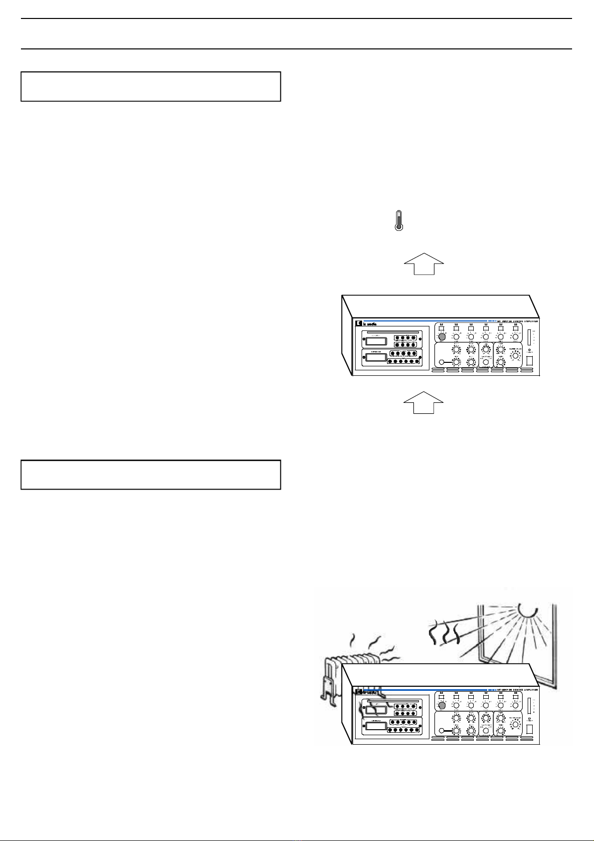
PREPARATION
40°C
Exhaustair
Freshair
false
PuttheMixerAmplifierinapositionwithenough
spaceenoughfreshairtominimisetheheatinthe
system.
DonotplacetheMixerAmplifierclosetoofheat
sourcesoraheater.
DonotexposetheMixerAmplifiersunlightor
heavydust.
DesktopMounting
Themixerampliferpullsfreshairthroughthesmall
holesinthebottomsheetandpushestheexhaust
airthroughthelongholesinthetopsheet.Please
makesurethattheinternalspaceoftherack
systemiscoolingandyouhavearoommaximum
temperatureof40°C..
Werecommendtoinstallacoolingsystematthe
rearsiteoftheracksystemtosupportthetransport
theexhaustairintheracksystem.
Cooling

7
SPECIALCHARACTERISTICS
!4MicrophoneinputswithdifferentPriorities
!1AUX
!6Zonesswitchableandadjustable
!Musicmuting
!Pre-AmplifierOutput
!AUX
!4Microphones
!PagingMicrophoneInput(12-pin)
!Telephone/EmergencyConnection
!115Vand230VMainsConnection
!24VBatteryConnection
!MonitorOutput
!CD/MP3-TunerMode
!100V- EntireSpeakers
!70V- EntireSpeakers
!25V- EntireSpeakers
!8ohm- EntireSpeakers
!100V- SpeakersofthefirstZone
!100V- SpeakersofthesecondZone
!100V- SpeakersofthethirdZone
!100V- SpeakersofthefourthZone
!100V-SpeakersofthefifthZone
!100V-SpeakersofthesixthZone
!LINEOUT
!600ohm-Monitor
!1V-Monitor
!8ohm-Monitor
!1Watt-Monitor
-PagingMicrophoneFunctions
-OutputFunction
-CommonFunction
-Inputs
-Outputs
PagingMicrophoneFunctions
OutputFunction
CommonFunction
Inputs
Outputs

8
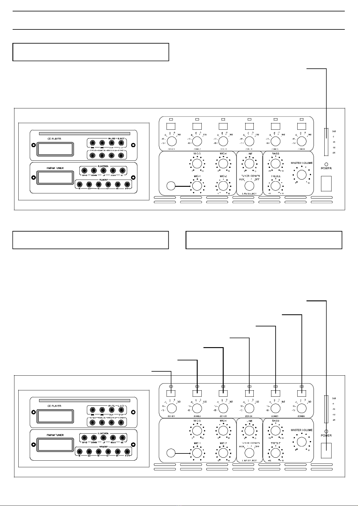
DEVICEFUNCTIONS FrontSide
-LED-Display
-On/Off-switch
-Zoning
-VU-Display
-MicrophoneInputMIC1
-MicrophoneController
-LINE-Controller
LINE-Select:
switchAUX/Tuner/CD-MP3/OFF
-ControllerBassandTreble
-ControllerMaster
Displayfortheactivation
LED-Display
Setting-uptheMixer-Amplifier
ON/OFF-Switch
VolumeControloftheacousticsignalsource
LINE-Controller
LINE-Select
switchAUX/Tuner/CD-MP3/OFF
ControllerfortheMicrophonevolume
MicrophoneController
Controlofthehighanddeepfrequency
ControlofallSignals
BassandTrebleController
ControllerMaster
ShowsthesaturationdegreeoftheMixerAmplifier
VU-Display
Usingtheoptionalitems
CD/MP3-Player&Tuner
ChoosingtheOutputZone
Zoning
Connectingamicrophone
MicrophoneInputMIC1
9
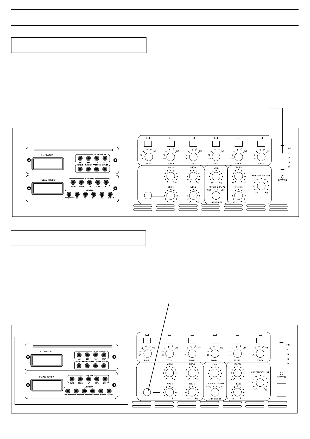
DEVICEFUNCTIONS FrontSide
TheLED-Displayshowstheoperationalreadiness
oftheMixerAmplifier.
LED-Display
Withthisswitchyouturnontheapparat.
PositionI=apparatison
Position0 =apparatisoff
Afterturningthemachineon,theLEDisshining
blue.Beforeturningthemachineon,theMaster
controllershouldbesettoalowvolume.
Inadditiontothenormal100Vlineoutputyoucan
select6Zonesbyusingthepushbuttonsonthe
frontpanel.
LED-Display
ON/OFF-Switch Zoning
ON/OFF-Switch
ZoneButtonNo.2
ZoneButtonNo.1
ZoneButtonNo.3
ZoneButtonNo.4
ZoneButtonNo.5
ZoneButtonNo.6
10
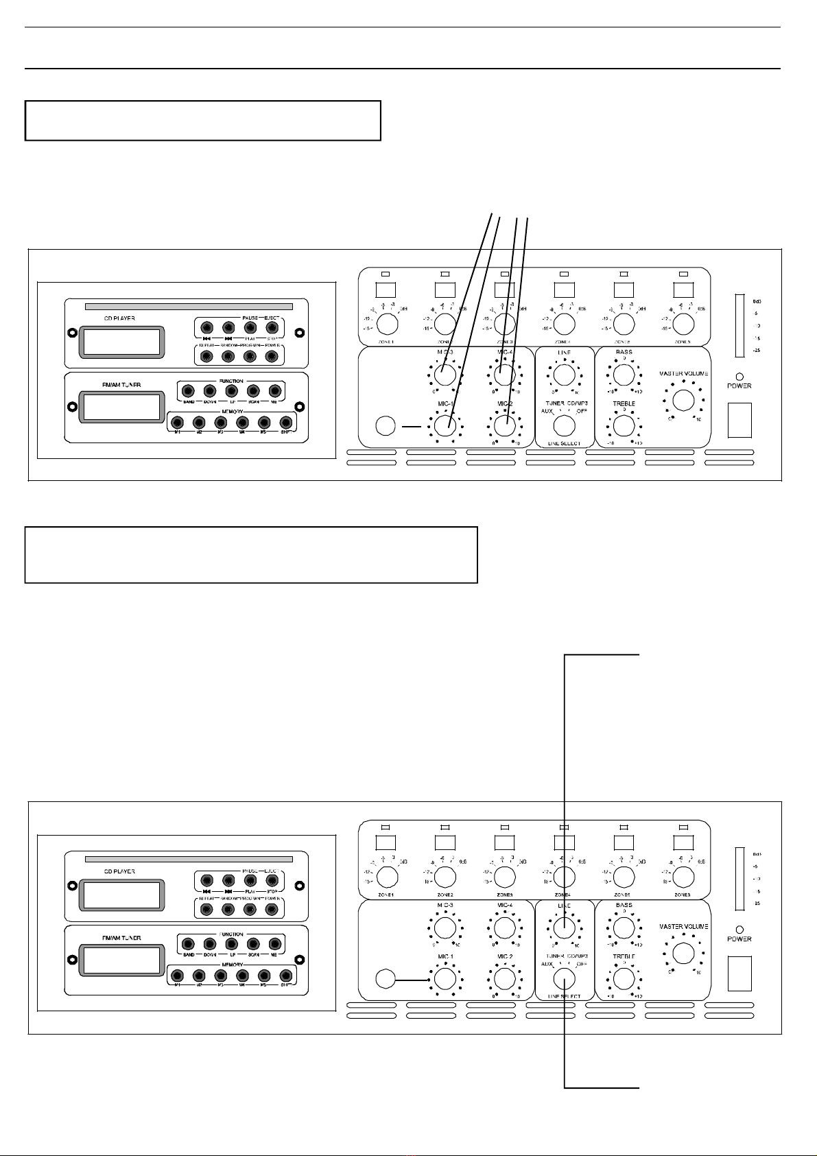
DEVICEFUNCTIONS FrontSide
TheVU-Displayshowsthesaturationdegreeofthe
MixerAmplifier.ThegreenLED’sindicatesthe
levelwhichcanberuncontinouslywithoutany
interferences.TheredLEDisiluminatedatthefull
saturationdegreeonly.Thislevelisnotappropriate
forenduringoperation.
VUmeter-Display:-25db,-18db,10,6,0db.
ThefirstmicrophoneMIC1ispriortoallothers.
MIC1beinginuseautomaticallygatesallother
microphones.Ifmusicishookeduptothesystem
whileanannouncementisbeingmade,thegate
shutsofthemusicsothatwiththespecificdesktop
microphonetheannouncementsignalcango
through.Thissettingwillremainuntilthe
announcementhasended.
Thenthenthemusicautomaticallyfadesbackin.
VU-Display
MicrophoneInput
MicrophoneInput(6,3mmchinch)
11
DEVICEFUNCTIONS FrontSide
Usingthiscontrolleryoucansetthevolumeofthe
microphones.
Youcanactivateconnectedsignalsoureceswith
theLINE-Selectswitch.
ThevolumeoftheconnectedSignalSourcescan
beadjustedbytheLINE-Controllerswitch.This
couldbeabuilt-inCD-Player,aoptionalTapeDeck
orabuilt-inTuner.
LINE-Select:switchAUX,Tuner,CD-MP3,OFF
LINE-Selectswitch
LINE-Controller
LINE-Controllerswitch
MicrophoneController
MicrophoneController
12
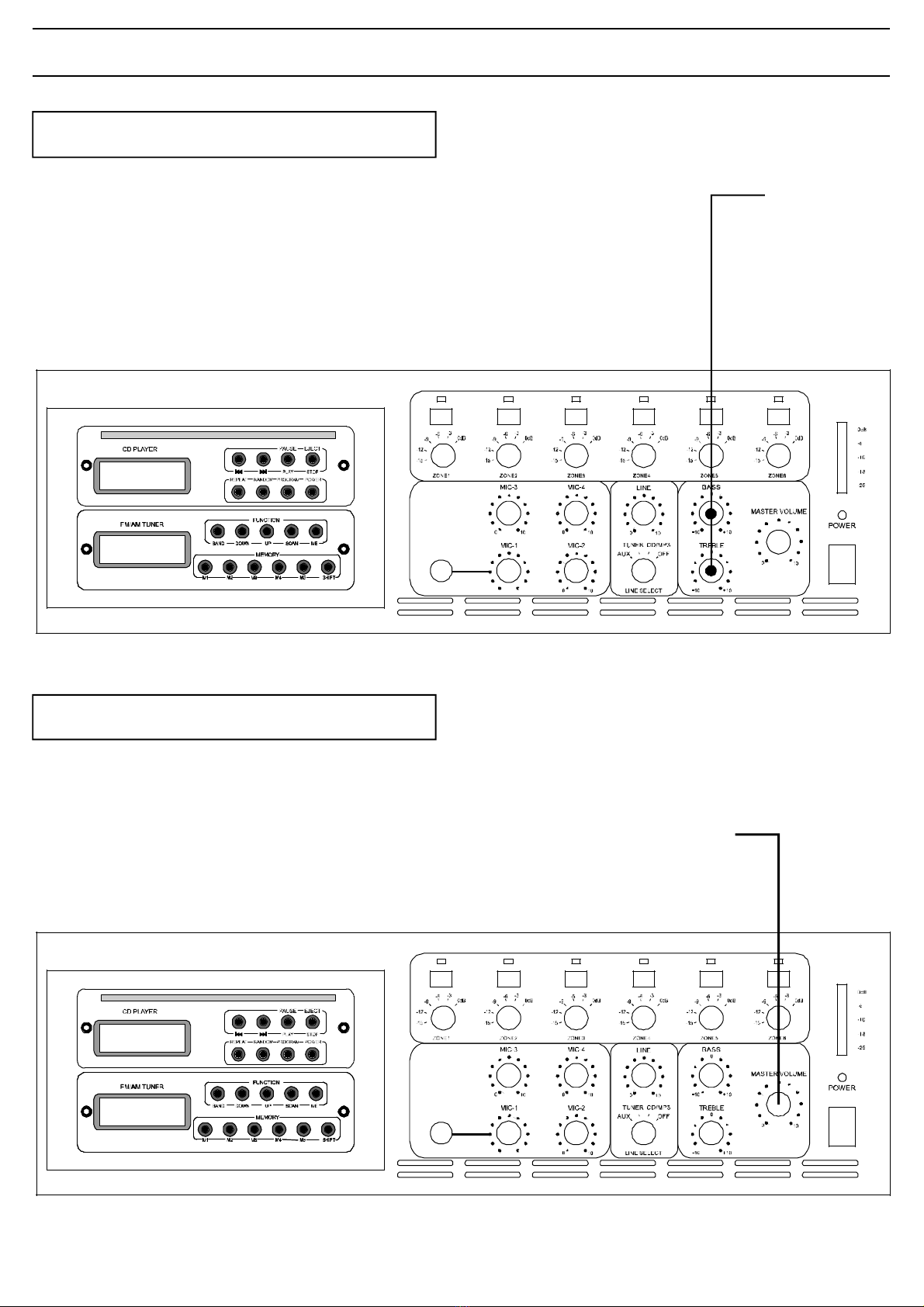
DEVICEFUNCTIONS FrontSide
Byusingthiscontrolleryoucanadjustthe
reproductionofdeepandhighfrequencies.
Thebasscontrolliftsorlowersfrequenciesnearto
100Hzat10dB.Thetreble-controlhasthesame
effectonfrequenciesnearto10.000Hz.
Themastercontroldrivesthevolumeofallsignals
beingprocessedbytheamplifier.
Signalsofthegencyinputareexcepted.TEL/EMER
TheycanbeadjustedattheRearsideoftheMixing
Amplifier.
BassandTrebleController
Controller
BassandTreble
MasterController
MasterController

13
DEVICEFUNCTIONS FrontSide
1.SelectCDmodewithLINEselectswitch.
2.PressPowerkeyonCD-Player
3.LoaddiscintoplayerandPlaystarts
automatically
4.PressPausekeyandtheplaywillbe
suspended.
PressPausekeytoresumeplay.
5.PresstheNextkeys(6+7)toselecttracks
6.PresstheRandomkey,randomappearsinthe
displayandtrackswillbeplayedoutofthe
sequence.
7.PresstheRepeatkeyonetimeandthecurrent
trackisrepeated.Whenthekeyispressed
twicethewholediscwillberepeated.Tocancel
thesefunctionspresstheRepeatkeyagain.
8.ProgrammingtheCD-PlayerinSTOPmode:
(a)PresstheProgramkey
(b)UsetheNext-orPreviouskeyto
selectatrack
(c)PresstheRepeatkeytomemorisethe
selectedtrackinyourprogram.Repeat
stages(b)and(c)toprogramamaximum
of20tracks.
(d)PressthePlaykeytostarttheprogram.The
programrepeatsitselfuntiltheCD-Player
isstopped.
CDOperation
ForFMreceptionconnectadipoleaerialusing
75coaxialtothesocketattherearoftheunit.Ω
ConnectthesuppliedantennatotheAMspring
loadedterminals.
1.SelectTUNERmodewiththeLINEselectswitch.
2.SelectAMorFMwiththeBANDkey.
3.UsetheUP/DOWNkeystosetafrequency
manuallyortheScankeytoautomatically
searchforthedesiredstation.
4.ToprogramastationpresstheMemorykey.
5.Pressamemorykey(M1toM5)orShiftkeyand
Memorykey(M6toM10)tostoreafrequency.
TunerOperation
1 2 3 4 5
6 7 8 9
1.CDdisplay
2.Repeatkey
3.Randomkey
4.Programkey
5.CDPowerON/OFFkey
6.Previouskey
7.Nextkey
8.Play/Pausekey
9.Stop/Ejectkey
1.M1(Memorykey)
2.M2(Memorykey)
3.M3(Memorykey)
4.M4(Memorykey)
5.M5(Memorykey)
6.Shiftkey
7.Bandselectkey
8.Downkey
9.Upkey
10.Scankey
11.MEkey
1 2 3 4 5 6
9 10 1187

14
DEVICEFUNCTIONS RearSide
-115Vand230VMainsConnection
-24VBatteryConnection
-100V/8 SpeakerOutput
-AerialConnection
-LINEOUT
-LINEINAUX
-Priorities
-InputsensitivityMIC1
-TelephoneInput
-Chime
-MONITOROUTPUT
-PagingMicrofone(12-pin)
-Topviewofallfunctions
Ω
Selectortoadaptthemainsconnection
115Vand230VMainsConnection
ConnectiontoUPS
24VBatterySupply
Terminalfor100V/8ohm-speakers
100V/8ohmSpeakerOutput
ConnectionofFManAMAntennas
Connectionofmonitordevices(fortracing)
Diagramconnectedwithallpossibledevices
Activatingaattentionsignalprecedingacall
Connectinganadditonalamplifier
EffectsofdifferentPriorityStatuses
AerialConnection
MONITOROUTPUT
Topviewofallfunctions
Chime
LINEOUT
Priorities
UsingtheTel.inputforemergencyannouncements
TelephoneInput
TerminalforLINEINdevices
LINEINAUX
ConnectionofPagingMicrofone(12-pin)
PagingMIC
AdjusttheinputsensitivityforMIC’sandLINE-Devices
InputsensitivityMIC1
15
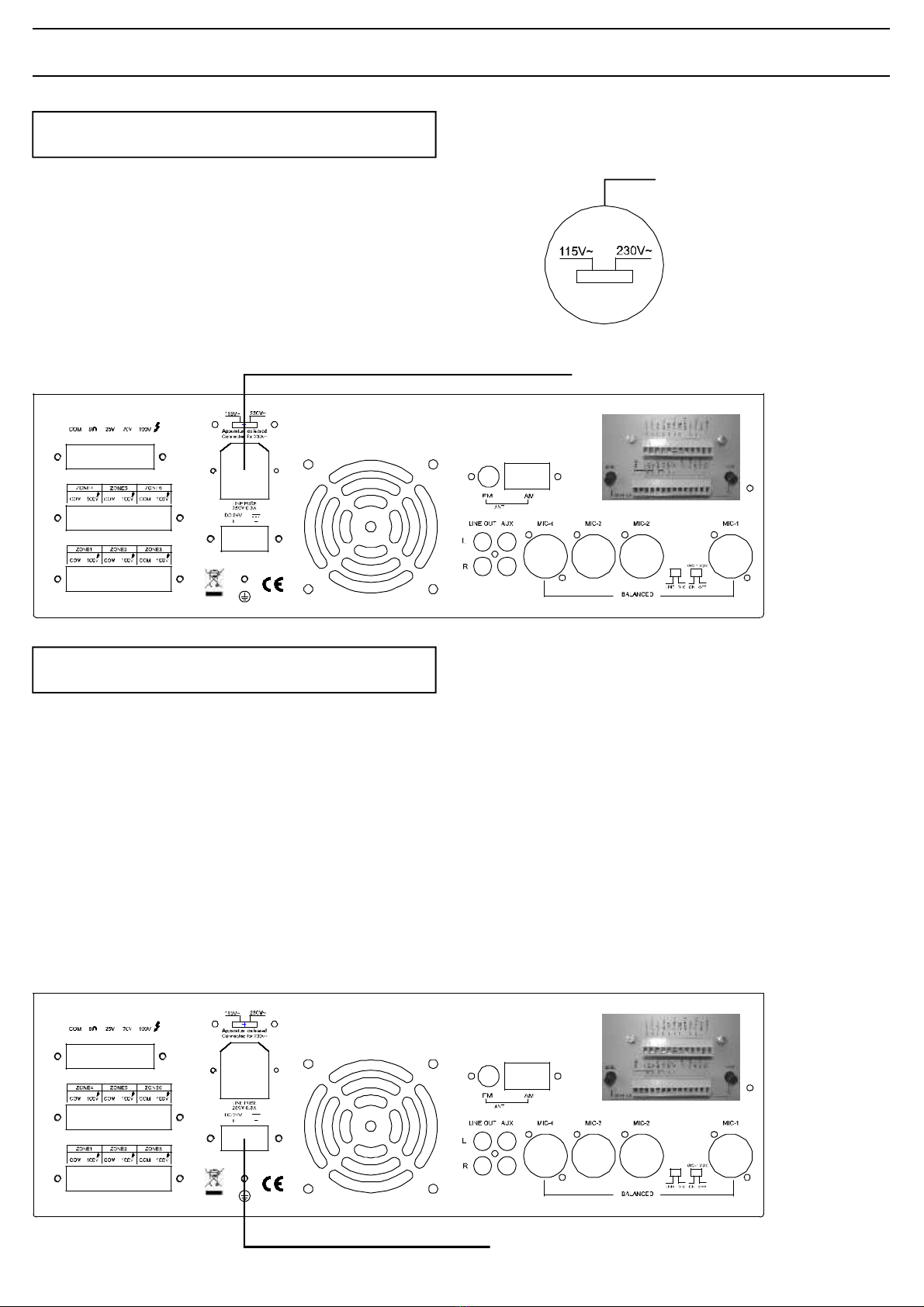
DEVICEFUNCTIONS RearSide
Theamplifierisfactorysetat230V(AC)mains
voltage.TheMainsSelectorisattherearsideof
theMixerAmplifier.
Youcansettheswitchto115Vifneccessaryby
pushingtheslideswitchfromrighttoleft.Please
disconnectthemainscablebeforechangingthe
voltagesupply.
Ensureyourselfthatthedeviceissettothelocal
mainsvoltagebeforeyouconnectit.
Youcanalsodrivethedevicewith24V(AC).
Thisisusefulincaseyourmainsconnectionis
brokendownandyoucanbypassthiswithan
uninteruptiblepowersupply(UPS).
Thedeviceisthenautomaticallydrivenbyexternal
batterypower,regardlesstothepositionofthe
ON/OFF-switch.
Electricalstabilityofthesystemisincreasedby
earthingthecase.
115Vand230VMainsConnection
MainsSelector
MainsSupply
24V-BatterySupply
24V-BatterySupply/UPSConnection
16
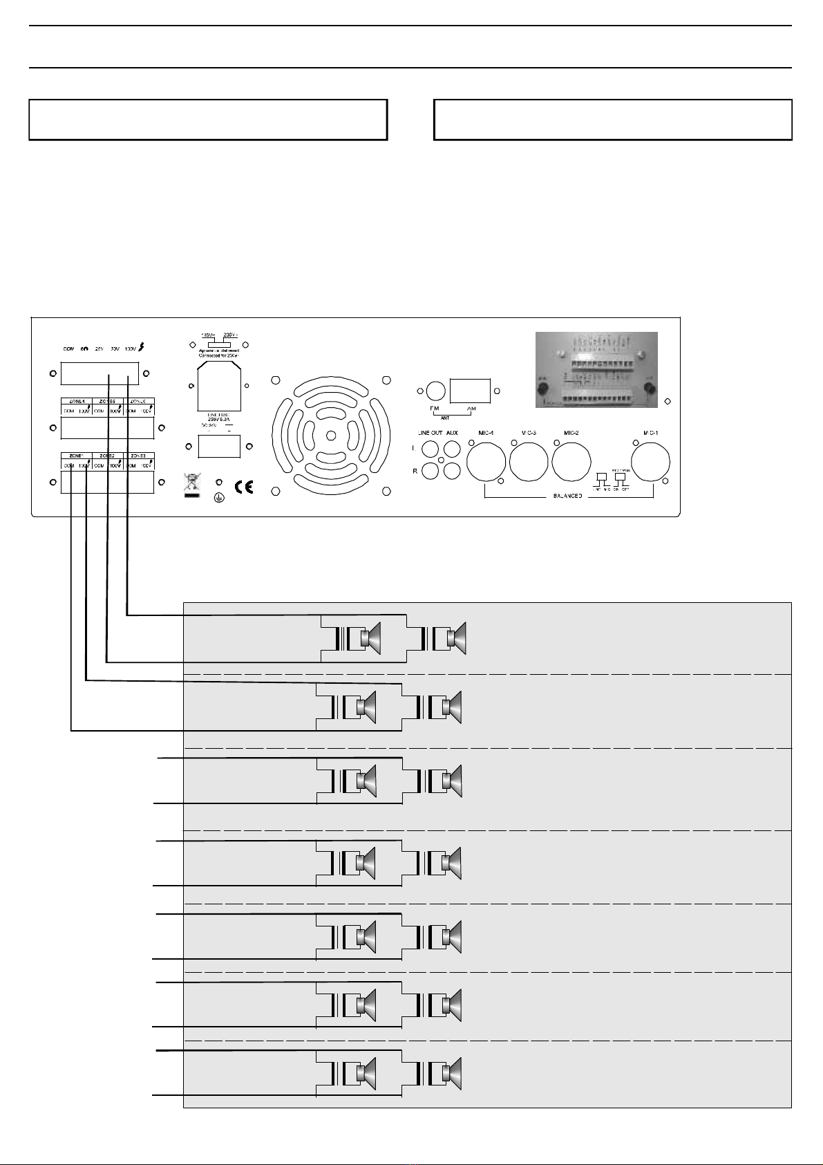
DEVICEFUNCTIONS RearSide
Theamplifierprovidessixdifferent100Vspeaker
Zones.Additionallyyoucanconnectthespeakers
withone25Vor70VZone.
!The100V-Outputreproducesallsignals
processedbytheMixerAmpliferoperatedin
thestandardmode.
Thisoutputallowsconnectionofstandardlow
impedancespeakers.Theminimumload
impedancemustbe8ohmWhentwoormore.
loudspeakersareconnected,ensurethattheyare
wiredinsuchaway,thattheloadimpedanceis
between8ohmand16ohm.
Line100,70,25V,8ohm
ZONE1(100V)
ZONE3(100V)
ZONE2(100V)
ZONE4(100V)
ZONE5(100V)
ZONE6(100V)
100VSpeakerOutput 8ohmSpeakerOutput
17
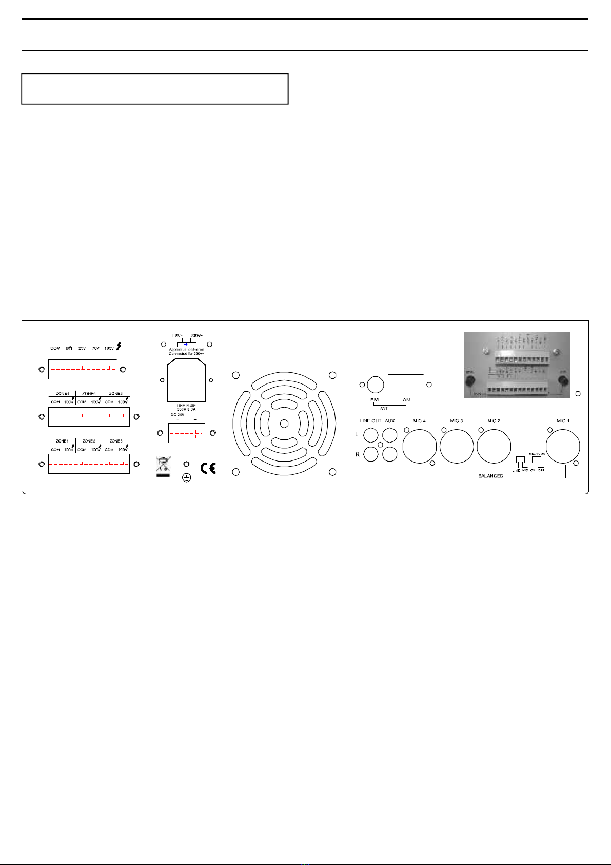
DEVICEFUNCTIONS RearSide
TheMT-AMP06providesthepossibilitytoconnect
twoantennas(FMandAM)attherearsideofthe
gear.TheconnectioncanbedonebytheAM-
clampsodertheFMjacket.
Antennaconnection
AerialConnection

18
DEVICEFUNCTIONS RearSide
LINEOUT
ThesestandardRCAphonosocketsprovidea
mixedoutputsuitableforconnectionofan
amplifier.
Pleasenote:Theconnectionofanpoweramplifier
isprovidingyouanadditionalzone.Thiszoneis
notadjustable(Music/Speech,Speechonly).The
powerforthe6zoneswillremainat240W.
Amplifier

19
DEVICEFUNCTIONS RearSide
Theequipmentprovidesanauxiliaryinputwhich
maybeusedforconnectingofothersignal
sourcessuchasaCD-orCassetteplayer.Aslide
switchislocatedonthefrontpanelforselectionof
AuxandCD.Thelinelevelcontroloperateson
eachoftheinputsources.Tooperateselectthe
desiredmusicsourceusingtheslideswitchand
turnthe"Line"controlclockwisetoincreasethe
volumeoranticlockwisetoreducethevolume.
TheAUX/CDinputsocketsarestandardRCA
phonosockets.Twosocketsaresuppliedand
thesearelinkedtogetherinternally.Thisallows
stereosignalsourcetobeusedwithouttheneed
toobtainaspeciallead.Howeveryoumaywishto
checkwiththemanufacturerofthesignalsource
toensurethatnodamagewillresultiftheleftand
rightoutputchannelsareworkinginparallel
operation.
Tape
LINEIN(CD/AUX)
This manual suits for next models
1
Table of contents
Other Fbt Amplifier manuals


