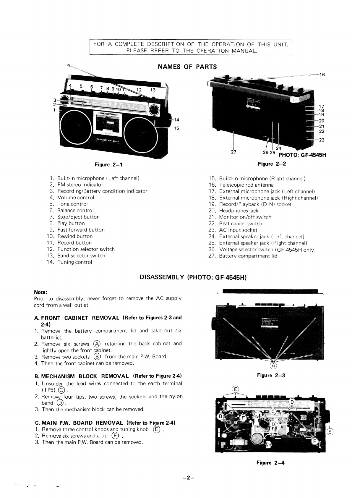
Sharp GF-4545H User manual

SHARP
SERVICE
MANUAL
Type:
Power
source:
Speakers:
Output
Power:
(DIN
45
324)
Semiconductors:
Dimensions:
Weight:
Input
terminals:
ATSM881127RCS
GF
-4545H
GF
-4545E
In
the
interests
of
user-safety
the
set
should
be
restored
to
its
original
condition
and
only
parts
identical
to
those
specified
be
used.
SPECIFICATIONS
Portable
stereophonic
cassette
tape
recorder
with
FM/MW/LW
3-band
radio
AC
IOV
SS
120V
220
240.
50/60Hz
D.C.
Internal
(Batteries):
(six
UM/SUM-1
or
R20)
(GF-4545H)
A.C.
240V,
50/60Hz
D.C.
OV
(six
HP2)
(GF-4545E)
10cm
Woofer
x
2
:
Horn
type
Tweeter
x
2
MPO
4000mW
(2000mW
+
2000mW)
on
A.C.
RMS
3200mW
(1600mW
+
1600mW)
on
D.C.
6-IC,
4-Transistor,
17-Diode,
2-LED
(Light
Emitting
Diode)
Width;
380mm
(15”)
Depth;
94mm
(3-3/4'’)
Height;
194mm
(7-3/4")
2./Kg
(5.9
lbs)
without
batteries
External
microphone
Jacks
(Left
and
Right)
Output
terminals:
Input/Output
terminals:
Other
terminals:
External
speaker
jacks
(Left
and
Right)
Headphones
jack
Record/Playback
socket
(DIN)
AC
input
socket
TAPE
RECORDER
SECTION
Type:
Tape:
Tape
speed:
Frequency
response:
Recording
system:
Erasing
system:
Wow
and
flutter:
Signal
to
noise
ratio:
RADIO
SECTION
Frequency
range:
Intermediate
frequency:
4-track
stereo
cassette
tape
recorder
Philips
type
compact
cassette
tape
4.8
cm/sec.
50
~
10,000Hz
AC
bias
AC
erasing
0.3%
(DIN
45
511)
45dB
PM?
80
106M
Z
MW;
520
~
1,620kHz
LV.
GhOO
=
ZOOKrZ
FM;
10.7MHz
MW/LW;
455kHz
(GF-4545H)
MW/LW;
465kHz
(GF-4545E)
Specitications
are
subject
to
change
without
prior
notice.
SHARP
CORPORATION
OSAKA,
JAPAN
GF-4545H
GF-4545E

FOR
A
COMPLETE
DESCRIPTION
OF
THE
OPERATION
OF
THIS
UNIT,
PLEASE
REFER
TO
THE
OPERATION
MANUAL.
NAMES
OF
PARTS
ap
ia
ca
4
<_—
hen
a!
2625
PHOTO:
GF-4545H
Figure
2—1
Figure
2—2
1.
Built-in
microphone
(Left
channel)
15.
Build-in
microphone
(Right
channel)
2.
FM
stereo
indicator
16.
Telescopic
rod
antenna
3.
Recording/Battery
condition
indicator
17.
External
microphone
jack
(Left
channel)
4.
Volume
control
18.
External
microphone
jack
(Right
channel)
5.
Tone
control
19.
Record/Playback
(DIN)
socket
6.
Balance
control
20.
Headphones
jack
7.
Stop/Eject
button
21.
Monitor
on/off
switch
8.
Play
button
22.
Beat
cancel
switch
9.
Fast
forward
button
23.
AC
input
socket
10.
Rewind
button
24.
External
speaker
jack
(Left
channel)
11.
Record
button
25.
External
speaker
jack
(Right
channel)
12.
Function
selector
switch
26.
Voltage
selector
switch
(GF-4545H
only)
13.
Band
selector
switch
2/7,
Battery
compartment
lid
14.
Tuning
control
DISASSEMBLY
(PHOTO:
GF-4545H)
Note:
Prior
to
disassembly,
never
forget
to
remove
the
AC
supply
cord
from
a
wall
outlet.
A.
FRONT
CABINET
REMOVAL
(Refer
to
Figures
2-3
and
2-4)
1.
Remove
the
battery
compartment
lid
and
take
out
six
batteries.
2.
Remove
six
screws
(A)
retaining
the
back
cabinet
and
lightly
open
the
front
cabinet.
3.
Remove
two
sockets
from
the
main
P.W.
Board.
4.
Then
the
front
cabinet
can
be
removed.
B.
MECHANISM
BLOCK
REMOVAL
(Refer
to
Figure
2-4)
Figure
2—3
1.
Unsolder
the
lead
wires
connected
to
the
earth
terminal
(TP5)
©).
2.
Remove
four
tips,
two
screws,
the
sockets
and
the
nylon
band
;
3.
Then
the
mechanism
block
can
be
removed.
.
MAIN
P.W.
BOARD
REMOVAL
(Refer
to
Figure
2-4)
.
Remove
three
control
knobs
and
tuning
knob
.
Remove
six
screws
and
a
tip
.
Then
the
main
P.W.
Board
can
be
removed.
WN
-Oo
Figure
2—4

MECHANICAL
ADJUSTMENT
=
FLYWHEEL
THRUST
CLEARANCE
ADJUSTMENT
(Refer
to
Figure
3-1)
eer
THRUST
ADJUST
WASHERS
1.
In
adjusting
and
assembling,
increase
or
decrease
the
0.3mm
a
number
of
thrust
adjust
washers
so
that
the
thrust
gap
Is
a
i:
maintained
at
0.1mm
~
0.3mm.
os
eae
|
Rea
| |
FLYWHEEL
JE
Figure
3—1
®
PINCH
ROLLER
PRESSURE
ADJUSTMENT
(Refer
to
Figure
3-2)
1.
Set
the
unit
in
play
mode.
2.
Push
the
point
(AY
with
a
tension
gauge
(0
gr.
to
1000
gr.)
to
make
the
pinch
roller
apart
from
the
capstan.
TENSION
GAUGE
(0
~
1000g)
Then,
check
that
the
tension
gauge
will
read
350
gr.
to
550
gr.
when
the
pinch
roller
stops
to
rotate.
3.
As
a
result
of
the
check
in
the
step
2
above,
if
the
reading
is
found
outside
the
range
of
350
gr.
to
550
gr.,
adjust
the
spring
of
pinch
roller
by
bending
it
or
replace.
PINCH
HOLLER
PINCH
ROLLER
SPRING
Figure
3—2
TORQUE
CHECK
AT
PLAY,
FAST
FORWARD
AND
REWIND
MODES
Put
a
torque
meter
cassette
in
the
cassette
compartment
of
the
set,
and
see
that
the
measured
torque
in
each
mode
Is
normal
as
follows.
Torque
meter
cassette
Measured
torque
Play
back
TW-2111
30
~
70
gram-cm
-
Fast-
forward
Rewind
TW-2231
70
~
140
gram-cm
TW-2231
70
~
140
gram-cm
TW-2111
TW-2231
Figure
3-3
="
AUTO
STOP
ADJUSTMENT
(Refer
to
Figure
3-4)
1.
Make
sure
that
the
auto
stop
mechanism
acts
rightly
at
the
tape
end,
2.
If
not,
adjust
the
stroke
by
bending
the
end
of
auto
stop
TAKE-UP
TURNTABLE
lever.
AUTO
STOP
ARM
dahlia
mH
oS,
pease
a
saree
gs a)
com.
oti
ek
Ta

1.
Connect
load
resistors
(4
ohm)
to
the
external
speaker
ELECTRICAL
MEASUREMENT
*
This
unit
operates
on
DC
9V.
Check
that
the
power
supply
is
exactly
9V
before
measurement.
Set
the
function
selector
switch
(SW2)
to
‘tape’
position.
*
#
RECORD/PLAYBACK
HEAD
AZIMUTH
ADJUSTMENT
(Refer
to
Figure
4-1)
WW
jacks
(J202,
J302)
and
connect
outputs
of
both
right
and
left
channels
to
the
vertical
and
horizontal
input
terminals
of
oscilloscope.
AC
V.T.V.M.
EXT
SP
(J302)
PLAYBACK
MODE
TEST
TAPE
MTT
—
114
(J202)
Figure
4—1
®
RECORD
AMPLIFIER
SENSITIVITY
CHECK
a:
(Refer
to
Figure
4-2)
1.
Connect
4
ohm
(2W,
5%)
dummy
load
resistors
to
the
3.
external
speaker
jacks
(J202,
J302)
and
connect
V.T.V.M.
4.
across
the
load.
EXT.
MICROPHONE
JACK
(J201,
J301)
SIGNAL
GENERATOR
ATTENUATOR
RECORD
MODE
_
Load
the
test
tape
(MTT-114,
10kKHz,
—10dB
recorded).
.
Place
the
unit
in
play
mode.
.
Adjust
the
head
azimuth
adjusting
screw
so
that
Lissajou’s
waveform
attains
the
maximum
and
the
same
phase
In
right
and
left.
OSCILLOSCOPE
Connect
signal
generator
for
1kHz,
—63dB
(OdB
=
1V)
to
the
external
microphone
jacks
(J201,
J301).
Load
the
tape
and
place
the
unit
in
record
mode.
If
the
record
amplifier
sensitivity
is
normal,
the
reading
on
the
V.T.V.M.
should
be
approximately
0.15V.
EXT.
SPEAKER
JACK
(J202,
J302)
V.T.V.M.
OSCILLOSCOPE
4
ohm
1
kHz
Figure
4-2
=
PLAYBACK
AMPLIFIER
SENSITIVITY
CHECK
(Refer
to
Figure
4-3)
1.
Connect
4
ohm
(2W,
5%)
dummy
load
resistors
to
the
3.
Place
the
unit
in
play
mode
with
the
volume
control
at
external
speaker
jacks
(J202,
J802)
and
connect
V.T.V.M.
across
the
load.
4.
2.
Load
the
test
tape
(MTT-112SP,
333Hz,
—20dB
recorded).
and
playback.
EXT.
SPEAKER
JACK
RECORD/
PLAYBACK
HEAD
PLAY
MODE
TEST
TAPE
MTT-112SP
maximum,
If
the
playback
amplifier
sensitivity
1s
normal,
the
reading
on
the
V.T.V.M,
should
be
0.45V
~0.7V.
V.T.V.M.
OSCILLOSCOPE
(J202,
J302)
Figure
4—3
~~

GENERAL
ALIGNMENT
INSTRUCTION
Should
it
become
necessary
at
any
time
to
check
the
the
most
sensitive
range
of
the
output
meter,
alignment
of
this
receiver,
proceed
as
follows.
3.
Use
a
non-metallic
alignment
tool.
1.
Set
the
volume
control
(VR3)
to
minimum.
4.
Repeat
adjustments
to
insure
good
results.
2.
Attenuate
the
signals
from
the
generator
enough
to
swing
AM
ALIGNMENT
CHART
AM
IF
and
MW
RF
ALIGNMENT
|,
Set
the
function
selector
switch
(SW2)
to
“‘radio’’
position.
2.
Set
the
band
selector
switch
(SW1)
to
”
SIGNAL
GENERATOR
step
|
JEST
3
DIAL
STAGE
CONNECTION
TO
INPUT
SIGNAL
SETTING
RECEIVER
FREQUENCY
MW"
position.
METER
CONNECTION
WHERE
TO
ADJUST
ADJUSTMENT
Connect
AM
sweep
Highest
Connect
an
Rotate
the
core
to
generator
to
the
455k
Hz
(400Hz,
frequency
oscilloscope
adjust
so
that
the
loop
antenna
and
30%,
AM
modu-
(to
extreme
between
the
waveform
becomes
place
it
near
the
bar
lation)
right)
test
point
maximum
and
sym-
antenna
(L5).
(TP6)
and
metrical
in
right
and
(The
output
of
ground
(TP5)
left
as
shown
in
signal
generator
A65kHz
(400H2
through
a
Fig.
5-1,
|
|
should
be
as
small
30%
AM
modu.
capacitor
(0.022
Repeat
this
until
as
possible.)
lation)
to
0.1
MFD.)
adjustment
be
satisfied.
Connect
AM
signal
510kHz
{(400Hz,
Lowest
fre-
Connect
Local
Adjust
so
as
to
generator
to
the
30%,
AM
modu-
quency
(to
V.T.V.M.
to
Oscillation
make
the
output
loop
antenna
and
lation)
extreme
left)
the
externa!
coll
be
maximum.
place
it
about
60cm
speaker
jack.
L6
(Set
the
volume
contro!
(VR3)
tomas”)
apart
from
the
bar
antenna
(L5).
(The
output
of
signal
generator
should
be
as
smail|
as
possible.
}
Frequency
coverage
1650kHz,
(400Hz,
30%,
AM
modu-
lation)
600kHz,
(400Hz,
30%,
AM
modu-
lation)
1400kHz,
(A0GHz,
30%,
AM
modu-
lation}
Oscillation
Same
as
step
2,
trimmer
TC5
Antenna
coil
L5
(MW)
Highest
fre-
Same
as
step
2.
quency
(to
extreme
right)
600kKHz
Same
as
step
2.
Same
as
step
2.
Same
as
step
2.
(See
Note
A)
Same
as
step
2.
Tracking
Antenna
trimmer
TC3
1400k
Hz
Same
as
step
2,
Same
as
step
2.
(See
Note
A)
Same
as
step
2.
2)
steps
2
and
3
or
4
and
5
until
no
further
improvement
can
be
made,
OSCILLOSCOPE
TEST
AM
SWEEP
LOOP
GENERATOR
ANTENNA
AM
IF
CURVE
AM
RF/IF
AMP
@
GND
(TPS5)
455k
Hz
(GF-4545H)
465kHz
(GF-4545E)
TEST
AM
SIGNAL
LOOP
EXT.
SPEAKER
GENERATOR
ANTENNA
L5
(MW)
JACK
(J202,
J302)
Figure
5—1
Check
the
alignment
of
the
receiver
antenna
coil
by
requires
less
inductance.
Change
loop
inductance
by
sliding
the
bringing
a
piece
of
ferrite
(such
as
a
coil
slug)
near
the
antenna
—
bobbin
toward
the
center
of
ferrite
core
to
increase
induct-
loop
stick,
then
a
piece
of
brass.
!f
ferrite
increases
output,
ance,
Or
away
to
decrease
inductance,
loop
requires
more
inductance.
If
brass
increases
output,
loop
i
ss
- 7
AMES
AIL
aes
tacit
Lap
cae
amet
ecu
eb
os
needle
ey
ce
Sek
oe

LW
RF
ALIGNMENT
1.
Set
the
function
selector
switch
(SW2)
to
“radio”
position.
2.
Set
the
band
selector
switch
(SW1)
to
“LW”
position.
ERATOR
SIGNAL
GEN
DIAL
CONNECTION
TO
|
INPUTSIGNAL
|
SETTING
RECEIVER
FREQUENCY
Connect
AM
signal
145kHz
(400Hz,
Lowest
fre-
METER
WHERE
TO
CONNECTION
ADJUST
ADJUSTMENT
Connect
Local
Adjust
so
as
to
generator
to
the
30%,
AM
modu-
quency
{to
V.T.V.M.
to
oscillation
make
the
output
loop
antenna
and
lation)
extreme
jeft)
the
external
coil
be
maximum.
place
it
about
60cm
speaker
socket
L7
(Set
the
volume
control
(VR3)
to
‘’max’’.)
apart
from
the
bar
antenna
(L5).
(The
output
of
signal
generator
should
be
as
small
as
possible.)
Frequency
coverage
Same
as
step
1
295kHz,
(400Hz,
|
Highest
fre-
Same
as
step
1.
Oscillation
Same
as
step
1.
30%,
AM
modu-
quency
(to
trimmer
lation)
extreme
right)
TC6
160kHz,
(400Hz,
30%,
AM
modu-
lation)
260kHz,
(400Hz,
30%,
AM
modu-
lation)
Same
as
step
1.
(See
Note
A}
Antenna
coi!
L5
(LW)
=
3
Tracking
—
4
Repeat
the
steps
1
and
2
or
3
and
4
until
no
further
improvement
can
be
made.
Antenna
trimmer
TC4
Same
as
step
1.
(See
Note
A)
TEST
V.T.V.M.
AM
SIGNAL
LOOP
EXT.
SPEAKER
GENERATOR
ANTENNA
L5
(LW)
JACK
(J202,J302)
Figure
6—1
VR3
TP5
VR4
j%TP7
TP4
TC3
TC4
LE
TCS
L7
TC6
LS
TPZ
TC2
TP1
TRS
TCl
11
74
13
“TP6
T6
T2
FS
L4
Figure
6—2
ALIGNMENT
POINTS
es

1,
Set
the
function
selector
switch
(SW2)
to
“radio”
position.
FM
ALIGNMENT
CHART
2.
Set
the
band
selector
switch
(SW1)
to
“FM”
position,
SIGNAL
GENERATOR
DIAL
METER
WHERE
TO
CONNECTION
TO
|
INPUT
SIGNAL
|
SETTING
|
CONNECTION
ADJUST
ADIUSTMENT,
RECEIVER
FREQUENCY
Connect
FM
sweep
10.7MHz
(400Hz,
|
Highest
Connect
an
Tote
2o
hs
|
Rotate
the
core
to
generator
to
the
100%,
FM
modu-
|
frequency
oscilloscope
adjust
so
that
the
TP3
through
lation)
(to
extreme
between
the
waveform
becomes
a
capacitor
(5pF).
right.)
test
point
(TP4)
symmetrical
in
right
Connect
its
ground
and
ground
(TP5)
and
left
as
shown
side
to
the
chassis
through
a
in
Fig.
7-1
(A)
:
ground
(TP2).
Capacitor
(Rotate
the
core
of
(0.022
to
0.1
T4
fully
counter-
MFD.)
|
clockwise.)
Same
as
step
1.
Same
as
step
1.
Same
as
|
Same
as
step
1.
T4
Adjust
the
core
so
step
1.
that
the
waveform
(“'s’’
curve}
becomes
Detection
symmetrical
in
up
and
down
with
the
best
linearity
as
Lt.
i
|
shown
in
Fig.
7-1
Repeat
the
steps
1
and
2
until
no
further
improvement
can
be
made.
Connect
signal
gene-
|
87.1MHz
{400Hz,
|
Lowest
Connect
Local
Make
the
output
be
rator
through
a
30%,
FM
modu-
frequency
V.T.V.M.
to
oscillation
maximum,
dummy,
including
lation)
(to
extreme
the
external
coll
Output
impedance
left)
speaker
jack.
L4
of
signal
generator
(Set
the
volume
4
to
the
FM
antenna
control
(VR3)
TPs
:
to
‘’max*’.)
|
(Refer
to
Figure
Frequency
|
7-3)
Ground
lead
of
coverage
generator
connected
to
the
receiver
chassis
(TP2).
Same
as
step
4.
JOOMHRz
(400Hz,
|
Highest
Same
as
step
4.
|
Oscillation
Same
as
step
4.
5
30%,
FM
modu-
frequency
trimmer
.
lation)
(to
extreme
TC1
right)
Same
as
step
4.
88MHz
(400Hz,
88MHz
Same
as
step
4.
RF
coil
Same
as
step
4.
30%,
FM
modu-
a2
lation)
Track
ing
ne
ee
i
eee
Pee
;
ame
as
step
4.
108MHz
(400Hz,
|
108MHz
Same
as
step
4,
RF
Same
as
step
4.
7
30%,
FM
modu-
trimmer
TC2
ik.
lation)
|
|
I
|
8
Repat
the
steps
4
and
5
or
6
and
7
until
no
further
improvement
can
be
made.
FM
IF
CURVE
“S"
CURVE
Figure
7—1
10.7MHz,
FM
SWEEP
GENERATOR
FM
FRONT
END
CIRCUIT
GND
GND
(TPS)
{TP2)
EXT.
SPEAKER
FM
SIGNAL
JACK
{J202,
J302})
FM
ANTENNA
GENERATOR
:
TERMINAL
DUMMY
(Fig.
7-3)
{TP2)
Figure
7—2
OSCILLOSCOPE
R
|
Z«
75
(onm)
<<
-
Re
«
—V\V\A——_-—-
TO
ANTENNA
Rt
=
37.5
(ohm)
(ohm
)
Re
er
at
=
50
(ohm)
=
h
poe
R2=*=
50
(ohm)
4
-__—.—_»
TO
CHASSIS
GROUND.
Z=
OUTPUT
IMPEDANCE
OF
SIGNAL
GENERATOR
Figure
7-3
EE
Ngee
ee
ee
i
ae
a>
See
Re
nd
ee
ae
ee
eT
eae
ee

ra
IR
cate
snag
ee
Saaiatinestin
atte
Tee
a
eae
tne
see
mae
32
a
ype
A
Lat
ene
+
at
ae
baa
Peres:
[Note
B]
(Refer
to
Figure
8-1)
There
are
5
kinds
of
ceramic
filter
(CF
1)
available
with
this
unit
and
they
are
given
color
indication
as
tabulated
below
to
differentiate
the
central
frequency
from
one
to
another
among
them,
When
other
ceramic
filter
than
the
one
(red)
having
the
central
frequency
of
10.7
MHz
are
used,
note
that
a
marker
(10.7
MHz)
of
FM
sweep
generator,
if
used,
will
be
deviated
—
therefore,
adjust
the
generator
by
putting
off
the
marker.
Central
frequency
(fo)
FM
MPX
ALIGNMENT
CHART
1,
Set
the
function
selector
switch
(SW2)
to
“radio”
position.
SIGNAL
GENERATOR
CONNECTION
TO
RECEIVER
Connect
FM
stereo
signal
generator
through
a
dummy,
including
output
impedance
of
gene-
rator
to
the
FM
antenna
(TP
1).
(Refer
to
Figure
7-3)
Ground
Jead
of
generator
connect
to
receiver
chassis.(TP2)
FM
STEREO
SIGNAL
GENERATOR
INPUT
SIGNAL
FREQUENCY
Exactly
98
MHz
(54dB)
unmodu-
jated
DUMMY
(Fig.
7-3)
|
|
EM
Ie
AMP.
DIAL
SETTING
10.64
MHz
+
30
kHz
10.67
MHz
+
30
kHz
10.70
MHz
+
30
kHz
10.73
MHz
+
30
kHz
10.76
MHz
#
30
kH2
Figure
8—1
2.
Set
the
band
selector
switch
(SW1)
to
‘‘FM
stereo
“‘posi-
tion.
METER
CONNECTION
4
WHERE
TO
ADJUST
ADJUSTMENT
Connect
fre-
quency
counter
through
a
100K
ohm
resistor
to
the
TP7.
Figure
8—2
1)
Turn
the
drum
fully
clockwise
and
stretch
its
cord
cover
the
Parts
in
the
numerical
order
.
2)
Turn
the
tuning
control
shaft
fully
counterclockwise,
and
fix
it
with
the
pointer
aligned
with
the
zero
(O)
point
on
the
dial
scale.
Figure
8-3
DIAL
CORD
STRINGING
—8-—
VR4
Adjust
for
19
+0.ikHz
TP7
FREQUENCY
COUNTER
Zero
Point

VOLTAGE
SELECTION
(GF-4545H
ONLY)
Take
care
to
check
the
voltage
setting
of
the
voltage
selector
before
connecting
supply
lead
plug
to
the
domestic
AC
outlet.
If
necessary
adjust
the
setting
as
follows:
Slide
the
voltage
selector
to
the
“110
~
120V”
or
“220
~
240V”"
position.
SELECTOR
30~
120V
220~240V
—_=
Figure
9—1
EQUIVALENT
CIRCUIT
OF
IC
FM
IF
FMF
OUTtN)
IN(2):
+e.
OUTt
uPC1212C
(1C2)
:
eee
eet!
-
¥
SA
—>+—
!
Rs
Os
es
Ss
oa
Input
G
G
I
‘
Ry
a
}y
Ae
2
Da
5)
oho
y
$n
ui
Q:
3
Re
+-
(a)
ae
poe
TOP
VIEW
8
7
6 §
ee
Ey
ae
ca
sue
a
we
Figure
9-3
EQUIVALENT
Figure
9-2
EQUIVALENT
CIRCUIT
OF
IC
(IC1)
CIRCUIT
OF
IC
(IC202,
IC302)
STEREO
/MONO
COMPARATOR
I9kHz
SWITCH
INPUT
MONITOR
P;
F
,P:F.
V.C.0.
STOP
V.C.0.
MUTING
SCHMITT
B
a.
14
6
fpecia
i
DRIVER
Input
NF.B
Output
GND
ALC
ALC
Vcc
Output
Input
Vec
COMPOSITE
PRE
AMP
L—ch
R—ch
LAMP
GNO
SELECTIVITY
SIGNAL
OUTPUT
OUTPUT
OUTPUT
DRIVER
CONTROL
INPUT
Figure
9-5
BLOCK
DIAGRAM
Figure
9-4
BLOCK
DIAGRAM
OF
IC
(IC2)
OF
IC
(1C201,
1C301)
—~9—
PACKING
METHOD
(GF-4545E
ONLY)
ACCESSORY
POLYETHYLENE
BAG
PACKING
ADD.
(LEFT)
(94F
H463042001)
PACKING
ADD.
(RIGHT)-
(94FH463042002)
PACKING
CASE
(94F
H433042003)
Figure
10—1
CAUTION
(GF-4545E
ONLY)
If
any
one
of
the
nylon
bands
shown
in
the
Figure
10—2
is
once
removed
for
some
reason,
be
sure
to
reprise
it
to
the
Original
place
in
the
same
appearance
as
before.
FUSE
GRAY
TRANSFORMER
Figure
10—2
—10—

}
4
4
if
ANTEN
\//
ROD
ANTENNA
QI
2SCI359B
Q2
2SCI359A
|
Ry
ut
cia
sa
ful
ae
gee
|
cn
eis
is2i39p
|
720K
47/50V
‘02
6s
Q|
Q2
=a]
iK
,
j
0.54V-—~
55V
[exeenes
©
Caps]
:
S
i
RIT
4.7K
@,
a
RIO
s
Re
TPS
Cg
L3
¢4
>
II
100
.
me
DGOO
,
2
o
1.22V
o>
|!
|
;
R
a
lI
Q| |©
|
me
eeaaee
os
eal
H
Tl
i
>
comes
;
Clee
RS.
pele
TOK
C5
CFI,
|
Raa
:
330P]1.2K
|.
lee
bo
‘en
ae
vei
raze
CL
4
@®
3
(CH)3.9K]
:
:
a
;
:
0
;
.72V
OV
4
6g
22
, J ,
6VA___(3.83V)_(4.37V)
o
:
|
n
r
MPCII9S7TC
168V
2.25V
2.25V
168V
482V
469V
Ci6
|.008
Cci7
005
<R8
560
R38
220
C67
2.2K
/
mi
y
\
03|
¥!
Cc?
ce
anee
!
02 02
ie)
Lwi
Miw
|FMmono
FMstereo
5
O 0
CH
Oo
Q
L
eee
:
Sswi-B
LW
Ww
LEM
no
FMstiereo
ie
ee
|
Oo
I
R29
it
OK
SWi-A
ly
Oe
ii:
| |
|
ww
|
Te
_
KLW)
‘
:
tH"
|
S
L205
74H,
ow
Cebp
|LW/MW
ANT.
07
3
5
(\
MOTOR
SWITCH
H
:
UMI
X6
C252
Che
o208¥,
*
Battery
Oey
io
ai
7
C54
|__|
.0228
.022
(ML)
|
(ML)
3)
25H
x)
ie
cep
ene
eee
|
¢
\SW7
|
a
\AC/OC
SELECTOR
\
SWITCH
Lwi
Miw
|FMmono
FMstereo
SWi-F
/
i
fe)
(s)
R44
39K
q
C66
/
loop
D202~0205
IN4002
x
4
C239~
C242 rere
02
x4
0202~
0208
IN4002
x
4
Sj
L203
)25
uH
t
C239
~
C242
P
ER
“
TRANSFORMER
02
x4
7
|
iil
°
;
we
C236
om
:
7
CNSI
CNPI
’
C2199
+
monitor
Desi
‘oe
cM20!
Lanta
9
a
i000
16v
Se
|
ma
DAE
7.
’
:
utah
OHO
)
470/16V
BUILT-IN
mel
Po
—
Z
3
:
VRI
yeov
|
22
207
R2
:
:
at
R-CH
O
EXT.
SPEAKER
JACK
O
L-CH
EXT.
MWC
ACK
:
L-CH
.
@
SP202
ig
TWEETER
cr
a
eS)
ae
7
L-CH
|
;
;
eS
.
i
2
SP20!
a
3S
7
co
eee
Some
ee
:
|
|
|
4
ohm
R-CH
<5
|
\
et
a
R39
_
f
‘
>)
:
.
yf
|earer
ene
sh
(C520,
monitor
|
ff
lo
4ohm
7
|
:
HEADPHONE
JACK
J
@
SP302
SS
a
a
a
=
ea
|
TWEETER
“
C)
R-CH
EXT:
MIC
JACK
SS
—_
ee
——
(20?
nese
ies
EXT.
SPEAKER
JACK
*:
TRY
0
RecH
eeitesit
ie
ae
WS
[Sap
C233
bc
Se
sts
“ole
P
L204
ron
{aE
.
oo
7K
__T
=,
Rees
atearichn
SWE-A
SW6-B
BEAT
CANCEL
O
S
DIN
ha
Q4
2SCI3I7R
a
|
__cmlicor
e
The
voltages
are
measured
with
VTVM
under
e
Unless
otherwise
specified
all
resistance
in
BESchiFTiGn
es
[swno.
[—pescriprion
[Position],
foane!
input
regent
SW1
(A
~
H)
Band
Selector
FM
Stereo—FM
Mono—MW—LW
SN
NO.
pea
es
e@
Unless
otherwise
specified
voltages
are
measur-
e
Unless
otherwise
specified
all
capacitance
in
SW2
(A
~
D)
Puncion
Celacior
SW6
(A,
B)
Beat
Cancel
ed
in
FM
mode.
microfarads.
P
=
micro
—
microfarads.
SW3
A.B)
eat
AC/DC
Selector
AC
—
DC
(
)
:
MWor
LW
mode.
e
(ML)
:
Mylar
film
capacitor
si
H
Swa
(A~
L)
Record/Play
back
SW8
(GF-4545H)
Voltage
Selector
110~120
—
220~240
:
Record
mode.
e@
(CH)
:
Temperature
compensating
ceramic
capacitor.
Motor
)
are
important
for
maintaining
the
ssafety
of
the
set.
Be
sure
to
replace
these
parts
with
specified
ones
for
main-
taining
the
safety
and
performance
of
the
set.
1
2
[Scares
eg
(GA
(egg
CoD
EE)
a
12
Figur.
jEMATIC
DIAGRAM
a
J
:
a42=
|
NOTES:
Parts
marked
with
“
/A\"
(Specifications
or
wiring
diagrams
of
this
model
are
subject
to
change
for
improvement
without
prior
notice.
)
|

Fee
Se
el
ea
4
a,
-
aa
Caaine
eenrnny
7
a
8
ee
Os
2
Nice
Oe
ee
TYPES
OF
TRANSISTOR
AND
LED
2SCI359A,B
=
=
=
2SCISI7R
POWER
TRANSFORMER
LE
<o
L
E
:
Emitter
>P
J302
Zp
SS
|
af
C
:
Collector
>
R-ch
|
—_
d
:
Yon
ORANG
Pe
I
EXT.
SPEAKER
JACK
B
:
Base
LN2IORP
RECORD/
PLAYBACK
HEAD
T7
POWER
ANODE
py
CATHODE
te
mele
O@
/
:
pee)
/
OO
NY)
SP202 SP302
TWEETER
TWEETER
L-ch
R-ch
ees
SW6
BEAT
CANCEL
=x
>
—<———_
©
SW3
MONITOR
SWITCH
ON
reczbatt.
ino.
J203
HE
ADPHONE
JACK
Qe
@
SG
ROD
ANTENNA
J204
DIN
SOCKET
J30I
R-ch
EXT.
MIC
JACK
J20!
L-ch
J
No
4
SO
220/240V
<7
—
swe
a
»)
SOI/SW7
VOLT,
S
CTOR
K
AC
INPUT
SOCKET
DETAGES.SELe
“SS
g
AC/DC
SELECTOR
SWITCH
adi
L.
Ilse2
(
(I
{
0
swe
SW!
GE
function
switch
band
selector
switch
<T¥
sleep
—
tape
—
radio
FMstereo
——
FMmono
—~
MW
—
LW
H
S$
ws
MOTOR
SWITCH
12
Figure
13
WIRING
SIDE
OF
P.W.
BOARD
—13—
|
,
=14=
|
i

:
a
Y
R
©
T+
ey
a
|
sia
Yo.
-
}
\
.
‘
®
.-
y
9
p
5
/
:
/
C
D
TOP
VIEW
As
Uf
bs.
IS
AN
\
4
FTD®)
a
ae
Se
|
—~
BOTTOM
VIEW
eer
ee
ee
ee
6
Figure
15
CABINET
EXPLODED
VIEW
|
!
Figure
16
MECHANISM
EXPLODED
VIEW
=15=
|
!
—16—
i
can
an
ITER
TE
nmr
one

REPLACEMENT
PARTS
LIST
“HOW
TO
ORDER
REPLACEMENT
PARTS”
To
have
your
oder
filled
promptly
and
correctly,
please
furnish
the
following
information.
1.
MODEL
NUMBER
3.
PART
NO.
2.
REF.
NO.
4.
DESCRIPTION
NOTES:
Parts
marked
with
““/\""
are
important
for
maintaining
the
safety
of
the
set.
Be
sure
to
replace
these
parts
with
specified
ones
for
maintaining
the
safety
and
performance
of
the
set.
REF.
NO.
PART
NO.
DESCRIPTION
CODE
REF.
NO.
—
PART
NO.
DESCRIPTION
CODE
INTEGRATED
CIRCUITS
L3
94FN730000559
FM
Emitter
Choke
L4
94FN730450307
FM
Oscillator
AA
IC1
94FN56UPC1018C
AM
Mixer,
AM/FM
IF
Amp.
AK
L5
94FN71MA108
MW/LW
Bar
Antenna
"
RH-IX1086AFZZ
—-
(uPC1018C)
L6
94FN80051HLO7.
~=—-
MW
Oscillator
_
IC2
94FN56UPC1197C
FM
Multiplex
Demodulator
AW
L7
94FN80052HLO7
LW
Oscillator
(uPC1197C)
L201
94FN740000250
Noise
Choke,
25uH
AE
10201,
301
-
94FN56UPC1158H
Equalizer
Amp.
(uPC1158H2)
L202
94FN740000102
Noise
Choke,
1mH
AE
-
VHIUPC1158H-1
L203
94FN740000250
Noise
Choke,
25uH
AE
1C202,
302
94FN56UPC1213C
Power
Amp.
(uPC1213C)
AV
L204
94FN80006LF10
Bias
Oscillator
L205,
206
94FN73CHL47U
Noise
choke,
47uH
AE
TRANSISTORS
TRANSFORMERS
Q1
94FN572031359B
FM
RF
Amp.
AC
°F
vsS2SC1359B/-1
(2SC1359B)
T1
94FN80071HFO7
~~
FM
Ist.
IF
AH
Q2
94FN572031359A
FM
Converter
AE
T2
94FN80052HFO7
FM
2nd.
IF
AH
(2SC1359A)
T3
94FN80053HFO07
FM
Discriminator
AF
Q3
94FN572031317R
Power
Supply
AF
T4
94FN80044HFO7
FM
Discriminator
AG
(2SC1317R)
T5
94FN80MF010
AM
IF
AH
Q4
94FN572031317R
Bias
Oscillator
AF
T6
94FN80026HGO7
+3
AM
Detector
AF
(2SC1317R)
AT?
94FN80413PT48
Power
(GF-4545E)
94FN80613PT48
Power
(GF-4545H)
DIODES
FILTERS
D1,2
94FN55CDG0000
Static
Protector
AB
(CDGOO)
CF1
94FN93072000F
FM
\F
AL
D3
94FN550VD1222
~~
Voltage
Regulator
AD
CF2
94FN94465A000M
AM
IF
(GF-4545E)
(VD1222)
94FN94455A000M
AM
IF
(GF-4545H)
D4
ee
94FN5501S2139B
~=Variable
Capacitor,
FM
AFC
AE
NF1,2
94FN940500038
FM
MPX,
38kHz
Band
AH
VHC1S2139-B-1
(1S2139B)
Elimination
D5,6
94FN5520A0090
FM
Detector
AD
(20A90)
CONTROLS
D7
94FN5500A0090
AM
Detector
AD
(OA90)
VC1,2
Variable
Capacitor,
Tuning
D8
94FN820531002
LED,
FM
Stereo
Indicator
AL
VC3,4
.
with
Trimmers
(LN210RP)
TC1,2
Se
eae
TC1:
FM
Oscillator
Trimmer
D9,
10
94FN55CDGO0000
FM
Overload
AB
TC3,4
TC2:
FM
RF
Trimmer
(CDGOO)
TC3:
MW
Antenna
Trimmer
D201
94FN5500A0090
ALC
Signal
Detector
AD
TC4:
LW
Antenna
Trimmer
(OA90)
TC5
94FN660241016
Trimmer,
MW
Oscillator
D202,
203
a
TC6
94FN660241016
Trimmer,
LW
Oscillator
,
|
94FN5501N4002
Rectifier
(1N4002)
AC
D204,
205
D206
94FN820531002
LED,
Record/Battery
AL
VR1,
Variable
Resistor
with
Bracket
Condition
Indicator
VR2
(A,B)
94FN61RVROO03
VR1:
100K
ohm
(B),
Balance
BB
(LN210RP)
VR3
(A,B)
VR2:
20K
ohm
(A),
Tone
D207
94FN550ZD05B1
Zener,
Voltage
Stabilizer
AE
VR3:
50K
ohm
(A),
Volume
(ZD5B1)
VR4
94FN61TRHO10B
10K
ohm
(B),
FM
MPX
AE
D208
94FN5501N4002
Noise
Suppression
AC
Adjust
(IN4002)
|
D301
94FN5500A0090
_
ALC
Signal
Detector
AD
ELECTROLYTIC
CAPACITORS
(OA90)
(Unless
otherwise
specified
electrolytic
capacitors
are
10V,
+50—10%
type.)
COILS
C19
VCEALU1HW474M_
.47MED,
50V,
+20%
AB
C28
VCEAAU1EW475A
4.7MEFD,
25V,+75
—10%
AB
L1
94FN73THBOO10
FM
Antenna
AC
C29,
32
VCEAAU1HW105A_
1MFD,
50V,
+75
—10%
AB
L2
94FN730400407.
~==FM
RF
AB
C33
VCEALU1HW105M
1MED,
50V,
+20%
AB
x
1
7
—
.
e
bP
lew
oe

REF.
NO.
C34
C36
C37
C41
C45,
46
C47
C48
C49
C51
C55
C201
C204
C205
C207
C210
C211
C214
C216
C217
C219
C220
C222
C223
C230
C232
C235
C237
C238
C243
C250
C251
C252
C301
C304
C305
C307
C310
C311
C314
C316,
317
C319
C320
C322
C323
C343
(Unless
otherwise
specified
capacitors
are
50V,
+20%,
Mylar
type.)
C1
C2
C3
C5
C6
C7,8
C9
C10
C11
C12
C13
C14
C15
PART
NO.
DESCRIPTION
VCEALU1HW474M
.47MFD,
50V,
+20%
VCEAAU1TAW107Y
100MFD
VCEAAU1AW476Y
47MFD
VCEALU1HW225M
2.2MFD,
50V,
+20%
VCEAAU1HW105A_
1MFD,
50V,
+75
—10%
VCEAAU1EW475A
4.7MFD,
25V,
+75
—10%
VCEAAUICW106Y
10MFD,
16V,
+50
—10%
VCEAAU1HW105A
1MFD,
50V,
+75
—10%
VCEAAU1AW476Y
47MFD
VCEAAU1AW107Y
100FMD
VCEAAU1HW104M_
.1MFD,
50V,
+20%
VCEAAU1HW105A_
1MFD,
50V,
+75
—10%
VCEAAU1AW476Y
47MFD
VCEAAU1CW106Y
10MFD,
16V,
+50
—10%
VCEAAU1EW335A
3.3MFD,
25V,
+75
—10%
VCEAAU1AW336Y
33MFD
VCEAAU1HW105A
1MFD,50V,
+75
—10%
VCEAAU1AW476Y
47MFD
VCEAAU1AW476Y
47MFD
VCEAAU1TAW227Y
220MFD
VCEAAU1AW107Y
100MFD
VCEAAU1CW477Y
470MFD,
16V,
+50
—10%
VCEAAU1AW227Y
220MFD
VCEAAUICW108Y
1000MFD,
16V,
+50
—10%
VCEAAU1CW478Y
4700MFD,
16V,
+50
—10%
VCEAAU1CW227Y
220MFD,
16V,
+50
—10%
VCEAAU1AW107Y
100MFD
VCEAAU1AW227Y
220MFD
VCEAAU1HW105A_
1MFD,
50V,
+75
—10%
VCEAAU1AW107Y
100MFD
VCEAAU1AW476Y
47MFD
VCEAAU1CW107Y
100MFD,
16V,
+50
—10%
VCEAAU1HW104M_
.1MFD,
50V,
+20%
VCEAAU1HW105A_
1MFD,
50V,
+75
—10%
VCEAAU1AW476Y
47MFD
VCEAAUICWI06Y
10MFD,
16V,
+50
—10%
VCEAAU1TEW335A
3.3MFD,
25V,
+75
—10%
VCEAAU1IAW336Y
33MFD
VCEAAU1HW105A_
1MFD,50V,+75
—10%
VCEAAU1TAW476Y
47MFD
VCEAAU1AW227Y
220MFD
VCEAAU1AW107Y
100MFD
VCEAAU1CW477Y
470MFD,
16V,
+50
—10%
VCEAAU1AW227Y
220MFD
VCEAAU1HW105A
1MFD,
50V,
+75
—10%
CAPACITORS
VCCSPU1HL330J
VCCSPU1HL2205
VCKZPU1HB502M
VCCSPU1HL220J
VCKZPU1HB502M
VCKZPU1HF2032
VCCSPU1HL4ROC
VCCCPU1HH330J
VCCSPU1HL331J
VCKZPU1HB502M
VCCCPU1HH6ROC
VCCCPU1HH4ROC
VCCCPU1HH180J
33PF,50V,
+5%,
Ceramic
22PF,
50V,
+5%,
Ceramic
.OO5MFD,
50V,
+20%,
Ceramic
22PF,
50V,
+5%,
Ceramic
OOSMED,
50V,
20%,
Ceramic
O2MFD,
50V,
+80
—20%,
Ceramic
4PF,50V,
+0.25PF,
Ceramic
33PF
(CH),
50V,
+5%,
Ceramic
330PF,
50V,
+5%,
Ceramic
OOSMED,
50V,
+20%,
Ceramic
6PF
(CH),
50V,
+0.25PF,
Ceramic
4PF
(CH),
50V,
+0.25PF,
Ceramic
18PF
(CH),
50V,
+5%
Ceramic
CODE
AB
AB
AB
AB
AB
AB
AB
AB
AB
AB
AB
AB
AB
AB
AB
AB
AB
AB
AB
AB
AC
AB
AD
AH
AB
AB
AB
AB
AB
AB
AB
AB
AB
AB
AB
AB
AB
AB
AC
AB
AB
AA
AA
AA
AA
AA
AA
AA
REF.
NO.
C16,
17
C18
C20,
21
C22,
23
C24
C25
C26,
27
C30,
31,
C35,
38
C39
C40
C42,
43
C44
C50,
oo
C57
C52,
54
C58
C59
C60
C61
C62
C63
C64
C66,
67
C68
C69
C202
C203
C206
C208
C209
C212
C213
C215
C218
C221
C224
C225
C226
C227
C229,
231
C233
C239,
240,
C241,
242
C245
C302
C303
C306
C308
C309
C312
C313
C315
C318
C321
C327
—18—
PART
NO.
VCKZPU1HB502M
VCCCPU1HH100J
VCKZPU1HB502M
VCKZPU1HF2032
VCCSPU1HL101J
VCCSPU1HL390J
VCKZPU1HF
1022
VCKZPU1HF203Z
VCQY
KU1HM473M
VCQSMT1HS471J
VCQYKU1HM102M
VCCSPU1HLS5ROC
VCKZPU1HF203Z
VCQY
KU1HM223M
VCKZPU1HF5022
VCKZPU1HF203Z
VCCSPU1HL390J
NVCQSMT1HS102J
VCCCPU1HH101J
VCQSMT1HS121J
VCQSMT1HS271J
VCCSPU1HL101J
VCCCPU1HH8ROD
VCQYKU1HM153M
VCQYKU1HM182M
VCQYKU1HM153M
VCQYKU1HM123K
VCQYKU1HM102M
VCCSPU1HL681J
VCQYKU1HM682M
VCQY
KU1HM393M
VCQYKU1HM102M
VCCSPU1HL101J
VCQY
KU1HM104M
VCQY
KU1HM472M
VCQYKU1HM223M
VCQYKU1HM183M
VCCSPU1HL101J
VCKZPU1HF104Z
VCQY
KU1HM472J)
VCKZPU1HF2032Z
VCKZPU1HF1042Z
VCQYKU1HM182M
VCQYKU1HM153M
VCQYKU1HM123K
VCQYKU1HM102M
VCCSPU1HL681J
VCOQYKU1HM682M
VCQYKU1HM393M
VCQYKU1HM102M
VCCSPU1HL101J
VCQYKU1HM104M
VCCSPU1HL101J
DESCRIPTION
OO5MFD,
50V,
+20%
Ceramic
10PF
(CH),
50V,
+5%,
Ceramic
OO5MFD,
50V,
+20%,
Ceramic
O2MFD,
50V,
+80
—20%,
Ceramic
100PF,
50V,
+5%,
Ceramic
39PF,
50V,
+5%,
Ceramic
001MFD,
50V,
+80
—20%,
Ceramic
O2MFD,
50V,
+80
—20%,
Ceramic
047MFD
470PF,
50V,
+5%,
Styrol
.001MFD
5PF,50V,
+0.25PF
Ceramic
O2MFD,
50V,
+80
—20%,
Ceramic
O22MFD
.OO5MED,
50V,
+80
—20%
Ceramic
O2MFD,
50V,
+80
—20%,
Ceramic
39PF,
50V,
+5%,
Ceramic
1000PF,
50V,
+5%,
Styrol
1OOPF
(CH),
50V,
+5%,
Ceramic
120PF,
50V,
+5%,
Styrol
270PF,50V,
+5%,
Styrol
100PF,
50V,
+5%,
Ceramic
SPF
(CH),
50V,
+0.5PF,
Ceramic
.O15MFD
.0018MFD
O15MFD
012MFD,
50V,
+10%,
Mylar
.0001MFD
680PF,
50V,
+5%,
Ceramic
.0068
MF
D
O39MFD
001MFD
100PF,
50V,
+5%,
Ceramic
.IMFD
0047MFD
O22MFD
.0018MFD
100PF,
50V,
+5%,
Ceramic
.IMFD,
50V,
+80
—20%,
Ceramic
.0047
MED,
50V,
+5%,
Mylar
O2MED,
50V,
+80
—20%,
Ceramic
.IMFD,
50V,
+80
—20%,
Ceramic
.00018MFD
015MFD
.012MED,
50V,
+10%,
Mylar
001MFD
680PF,
50V,
+5%,
Ceramic
.O68MFD
O39MFD
001MFD
100PF,
50V,
+5%,
Ceramic
.IMFD
100PF,
50V,
+5%,
Ceramic
CODE
AA
AA
AA
AA
AB
AA
AA
AB
AB
AA
AB
AA
AA
AA
AB
AA
AB
AB
AB
AA
AB
AA
AA
AA

REF.
NO.
(Unless
otherwise
specified
resistors
are
1/4W,
+5%
Carbon
type.)
R1
R2
R3
R4
RS
R6
R7
R8
R9
R10
R11
R12
R13
R14
R15
R16
R17,
18
R19
R20
R21
R22,
23
R24
R25
R26
R27
R28
R29
R30
R31
R32
R33
R34
R35
R36
R37
R38
R39
R41
R42
R43
R44
R45
R201
R202
R203
R204
R205
R206
R207
R208
R209
R210
R211
R212
R213
R214
R215
R216
R217
R218
R219
R221
R223
R224
R225
R226
R227
DESCRIPTION
PART
NO.
RESISTORS
VRD-ST2EY102J
1K
ohm
VRD-ST2EY103J
10K
ohm
VRD-ST2EY222J
2.2K
ohm
VRD-ST2EY561J
560
ohm
VRD-ST2EY122J
1.2K
ohm
VRD-ST2EY103J
10K
ohm
VRD-SU2EY220J
22
0hm
VRD-SU2EY561J
560
ohm
VRD-ST2EY224J)
220K
ohm
VRD-ST2EY101J
100
ohm
VRD-SU2EY104J
100K
ohm
VRD-SU2EY104J
100K
ohm
VRD-SU2EY101J
100
ohm
VRD-ST2EY222J
2.2K
ohm
VRD-ST2EY102J
1K
ohm
VRD-SU2EY102J
1Kohm
VRD-ST2EY472J
4.7K
ohm
VRD-ST2EY104J
100K
ohm
VRD-SU2EY102J
1K
ohm
VRD-ST2EY331J
330
0hm
VRD-ST2EY472J
4.7K
ohm
VRD-SU2EY183J
18K
ohm
VRD-ST2EY331J
330
ohm
VRD-ST2EY470J
47
0hm
VRD-ST2EY332J
3.3K
ohm
VRD-SU2EY220J
220hm
VRD-SU2EY103J
10K
ohm
VRD-SU2EY473J
47K
ohm
VRD-ST2EY472J
4.7K
ohm
VRD-ST2EY103J
10K
ohm
VRD-ST2EY471J
470
ohm
VRD-SU2EY471J
470
ohm
VRD-ST2EY682J
68K
ohm
VRD-ST2EY103Y
10K
ohm
VRD-ST2EY222J
2.2K
ohm
VRD-ST2EY221J
220
ohm
VRD-SU2EY393J
39K
ohm
VRD-SU2EY101J
100
ohm
VRD-SU2EY331J
330
0hm
VRD-SU2EY392J
3.9K
ohm
VRD-SU2EY393J
39K
ohm
VRD-ST2EY561J
560
ohm
VRD-ST2EY222J
2.2K
ohm
VRD-SU2EY102J
1K
ohm
VRD-ST2EY102J
1K
ohm
VRD-SU2EY102J
1K
ohm
VRD-ST2EY181J
180
ohm
VRD-ST2EY681J
680
ohm
VRD-ST2EY123J
12K
ohm
VRD-ST2EY224J
220K
ohm
VRD-ST2EY183J
18K
ohm
VRD-ST2EY471J
470
ohm
VRD-ST2EY102J
1Kohm
VRD-ST2EY222J
2.2K
ohm
VRD-ST2EY103J
10K
ohm
VRD-ST2EY222J)
2.2K
ohm
VRD-ST2EY102J
1Kohm
VRD-ST2EY820J
82
o0hm
VRD-ST2EY220J
22o0hm
VRD-ST2EY183J
18K
ohm
VRD-ST2EY101J
100
ohm
VRD-SU2EY181J
180
ohm
VRD-ST2EY333J
33K
ohm
VRD-ST2EY270J
27
0hm
VRD-ST2EY272J
2.7K
ohm
“VRD-SU2EY102J
1K
ohm
VRD-ST2EY102J
1K
ohm
CODE
AA
REF.
NO.
R228
R229
R230
R231
R232
R301
R302,
303
R304
R305
R306
R307
R308
R309
R310
R311
R312
R313
R314
R315
R316
R317
R318
R319
R328
R329
R330
R331
"-
OOnN
Oo
sf
WON
=
=
©
—_
NO
13
14
15
16
17
18
19
20
21
22
23
25
26
27
28
29
31
32
33
36
37
38
39
—19—
PART
NO.
VRD-ST2EY822J
VRD-ST2EY334J
VRD-SU2EY1ROJ
VRD-ST2EY
103J
VRD-ST2EY151J
VRD-ST2EY222J
VRD-ST2EY102J
VRD-SU2EY102J
VRD-ST2EY181J
VRD-ST2EY681J
VRD-ST2EY123J
VRD-ST2EY224J
VRD-ST2EY183J
VRD-ST2EY471J
VRD-ST2EY102J
VRD-ST2EY222J
VRD-ST2EY103J
VRD-ST2EY222J
VRD-ST2EY102J
VRD-ST2EY820J
VRD-SU2EY220J
VRD-ST2EY183J
VRD-ST2EY101J
VRD-ST2E
Y822J
VRD-ST2EY334J
VRD-SU2EY1ROJ
VRD-ST2EY103J
DESCRIPTION
8.2K
ohm
330K
ohm
1
ohm
10K
ohm
150
ohm
2.2K
ohm
1K
ohm
1K
ohm
180
ohm
680
ohm
12K
ohm
220K
ohm
18K
ohm
470
ohm
1K
ohm
2.2K
ohm
10K
ohm
2.2K
ohm
1K
ohm
82
ohm
22
ohm
18K
ohm
100
ohm
8.2K
ohm
330K
ohm
1
ohm
10K
ohm
MECHANICAL
PARTS
94FH15905F
1013
94FH15905B1019
94FH109051005f
94FS189051055a
94FH15905F
1005
94FH15905F
1006
94FH15905F
1007
94FH15905F
1008
94FH15905F
1002
94FH15905F
1010
94FH159051013
94F
H15905B1027
94FH159051015
94FS189051016b
94FH159051067b
94FH159051018a
94FH159051019
94FH27905A1014
94FH179051020
94FS18905A1007
94FN910940924
94FN79RHO040
94FN790262000
94FH179051028
94FH10905A1010
94FH15905A1004
94FH15905A1005
94FH15905F
1014
94FH179051033a
94FH159051024
94FH15905F
1012
94FH15905F
1015
94FH180823114
94FH15905F
1004
94FH159051043C
Main
Chassis
Assembly
Sub
Chassis
Assembly
Holder,
Record/Playback
Head
Spring,
Sub
Chassis
Lever,
Eject/Stop
Lever,
Playback
Lever,
Fast-Forward
Lever,
Rewind
Lever,
Record
Safety
Record
Lever
Assembly
Lever,
Cassette
Holder
Lock
Release
Lever,
Cassette
Holder
Lock
Contact,
Tape
Spring,
Auto
Stop
Lever
Lever,
Auto
Stop
Arm,
Auto
Stop
Bracket,
Auto
Stop
Arm
Shaft,
Auto
Stop
Lever
Pinch
Roller
Assembly
Spring,
Pinch
Roller
Motor
Head,
Record/Playback
Head,
Erase
Gear,
Fast-Forward
Idler
Bracket,
Sub
Chassis
Lever,
Function
Lever
Lock
Plate,
Record
Lever
Lock
Take-up
Idler
Assembly
Gear,
Take-up
Idler
Take-up
Turntable
Assembly
Supply
Turntable
Assembly
Fast-Forward/Rewind
Drive
Arm
Assembly
Spring,
Back
Tension
Stopper,
Back
Tension
-Lever,
Anti
Record
(Erase
Proof)
CODE
AA
AD
AD
AE
AG
AB
AG
AD
AB
AB
AD
AD
AD
AB
AM
AB
BE
BB
AU
AC
AC
AF
AN
AC
AD

REF.
NO.
PART
NO.
DESCRIPTION
CODE
REF.
NO.
PART
NO.
DESCRIPTION
CODE
40
94FH319051001
Belt,
Drive
AK
127
94FN69RA020
Telescopic
Rod
Antenna
AY
42
94FH15905B1031
Flywheel
Bracket
Assembly
AE
128
94FH102021030d
Bracket,
Speaker
(Woofer)
AC
43
94FH179051049a
Flywheel
Assembly
AW
130
94FH373040031
Handle
Grip
AQ
44
94FH17905F
1011
Pulley,
Motor
AE
131
94FH371040012c
Bracket,
Handle
AQ
45
94FH15905C1019
_=—~
Plate,
Cassette
Retaining
AE
132
94FH371040014
Bushing,
Handle
AD
46
94FH17905B1013
_—-
Fast-Forward/Rewind
AN
133
94FS053040029
Cushion,
Battery
AA
Drive
Assembly
134
94FS053040033
Ribbon,
Battery
47
94FS011042609
Screw,
Motor
AA
135
94FH503040023
Felt,
Back
Cabinet
(Side)
48
94FH279051060a
Spacer,
Motor
Retaining
AB
137
94FHO52030017
Bracket,
Built-in
AC
49
94FS059051061
Cushion
Rubber,
Motor
AB
Microphone
50
94FS180713070
Spring,
Cassette
Lock
Lever
AC
|
A\
138
94FHO45070013h
Cover,
AC
Input
Socket
AD
51
94FS180713072
Spring,
Play
Lever
AB
139
94FH102040037b
Holder,
AC
Input
Socket
AB
52
94FS180713049
Spring,
Record
Lever
AB
140
94FHO9C2040038
#
Spacer,
AC
Input
Socket
AC
Lock
Plate/Take-up
141
94FS031040000
Stopper,
Tuning
Shaft
AA
idler
Arm
142
94FH17C2031004
Pulley,
Dial
Cord
Stringing
AB
53
94FS180713033
Spring,
Record
Safety
AB
143
94FH172120026a
Pulley,
Dial
Cord
Stringing
Lever/Anti
Record
144
94FH179070017
Pulley,
Dial
Cord
Stringing
54
94FS180823149
Spring,
Head
Azimuth
AB
145
94FS180713055
Spring,
Dial
Cord
Stringing
AC
55
94FS180713113
Spring,
Fast-Forward/Rewind/
AE
/\
146
94FN85001VS+0
Holder,
Fuse
Record/Function
Lever
147
94F
HO93040034
Spacer,
Voltage
Selector
Lock
Lever
Switch
(GF-4545H)
56
94FS180713054
Spring,
Eject/Stop
Lever
AB
CM201,301
94FN780363000
Built-in
Microphone
57
94FS189051078a
Spring,
Auto
Stop
Arm
AC
J201,
301
94FN8702201350
#£
Jack,
External
Microphone
58
94FH1130400081
Button,
Eject/Stop,
AF
J202,
302
94FN87101500D
Jack,
External
Speaker
Playback,
Rewind
J203
94FN87JAK064
Jack,
Headphones
AV
59
94FH113040030
Button,
Fast-Forward
AE
J204
94FN87JAKO76
Socket,
Record/Playback
60
94FH1130400082
#Button,
Record
(DIN)
61
94FN100300000
Lug,
Ground
A,
$O01/SW7
94FN86008V000
Socket,
AC
Input
with
62
94FS011062003
Screw,
Motor
Pulley
AC/DC
Selector
Switch
Retaining
(SW7)
SP201,
301
94FN784041004
Woofer,
4
ohm
MISCELLANEOUS
SP202,302
94FTBB206A6
Tweeter
SW1
(A~H)
94FN778411084
Switch,
Band
Selector
101
94FHO130400021
Cabinet,
Front
BF
SW2(A~D)
94FN770471043
Switch,
Function
Selector
AQ
102
94FHO230400012
Cabinet,
Back
SW3
(A,B)
94FN77101A1022
Switch,
Monitor
on/off
AH
103
94FH153040003
Chassis,
Radio
SW4
(A~L)
94FN77SLS021
Switch,
Record/Playback
AS”
104
94FHO043040004
Lid,
Battery
Compartment
SW5
94FN77LFS202
Switch,
Motor
AN
105
94FHO53040005
Holder,
Cassette
AT
SW6
(A,
B)
94FN77101A1022
Switch,
Beat
Cancel
106
94FH8830400062
Overlay,
Cassette
Holder
4\
SW8
94FN77SLS223
Switch,
Voltage
Selector
107
94FH213040007
Window,
Dial
Scale
AS
(GF-4545H)
108
94FH113040009
Knob,
Volume/Tone/
Balance
AD
|
A\
F1
94FN840001000
Fuse,
T1A
109
94FH111040017
Knob,
Tuning
A
94FN89011B000
AC
Supply
Cord
(GF-4545E)
110
94FH11304001
1
Knob,
Slide
Switch
AD
|A
94FN89023VS+0
AC
Supply
Cord
(GF-4545H)
111
94FH173040012
Drum,
Dial
Cord
Stringing
AG
CNP1
94FN10TM604
Plug,
4-pin
AF
112°
94FH323040013
Dial,
Pointer
AF
CNP2
94FN10TM603
Plug,
3-pin
AF
113
94FH383040014
Tuning
Shaft
AB
CNP3
94FN10TM605
Plug,
5-pin
AG
114
94FH153040015
Mirror,
Cassette
AC
CNP4
94FN10TM605
Plug,
5-pin
AG
Compartment
CNS1
94FN97CW604
Socket,
4-pin
AQ
115
94FH8130400162
Badge,
Model
Name
(Tip
and
Lead)
116
94FH50304001
7
Sheet,
Shield
AC
CNS2
94FN97CW603
Socket,
3-pin
AH
117
94FS183040018
Spring,
Battery
(+)
(—)
AD
(Tip
and
Lead)
118
94FS183040019
Spring,
Battery
(—)
AC
CNS3
94FN97CW605
Socket,
5-pin
AP
119
94FH153040020
Battery
Terminal
AE
(Tip
and
Lead)
120
94FH8330400212
_
Dial
Scale
CNS4
94FN97CW705
Socket,
5-pin
AL
121
94FS183040022
Spring,
Cassette
AD
(Tip
and
Lead)
Compartment
94FW520040260
4-core
Wire,
260mm
AH
122
94FH8030400101
Punching
Metal,
Speaker
AS
94FW520040100
4-core
Wire,
100mm
AE
(Woofer)
94FH463042001
Packing
Add.
(Left)
123
94FHO93040024
Spacer,
Speaker
(Woofer).
AD
94FH463042002
Packing
Add.
(Right)
124
94FH153040025
Ground
Plate
(FM)
94FH433042003
Packing
Case
AY
94FH824545H700
_——
Plate,
Specification
94FH41-GF4545H
Operation
Manual
(GF-4545H)
|
125
(GF-4545H)
94FH41-GF4545E
Operation
Manual
(GF-4545E)
}
94FH824545E705
_~=—Os-
Plate,
Specification
.
(GF-4545E)
94FH823040028
Plate,
Caution
126
(GF-4545H)
94FH824545E710
_~—sC—
Plate,
Caution
(GF-4545E)
ee
A8108-3075NS
Printed
in
Japan

>
SHARP
SERVICE
MANUAL
/SERVICE-ANLEITUNG/
MANUEL
DE
SERVICE
a
re
rae
A:ito
Program
Search
System
Note
for
users
in
UK:
Recording
and
playback
of
any
material
may
require
consent
which
SHARP
are
unable
to
give.
Please
refer
particularly
to
the
provisions
of
Copyright
Act
1956,
the
Dramatic
and
Musical
Performers
Protection
Act
1958,
the
Performers
Protection
Acts
agit
and
1972
and
to
any
subsequent
statutory
enactments
and
orders.
<<)
By
the
Specification
Label
at
the
back
of
units,
it
is
possible
to
distinguish
Japanese
products
from
SRC’s
ones.
In
case
that
the
Label
has
an
indication
of
“MADE
IN
JAPAN”,
CD)
Durch
den
Spezifikationsaufkleber
an
der
Riickseite
des
Gerates
ist
es
modglich,
die
japanischen
Produkte
von
SRCs
unterscheiden.
Wenn
das
Anzeichen
CF)
Il
est
possible
de
distinguer
les
produits
japonais
de
ceux
de
SRC
par
I|’étiquette
des
caractéristiques
qui
se
trouve
a
I’arriére
des
appareils.
Au
cas
ot
I’étiquette
porte
une
indication
“MADE
IN
JAPAN”,
“MADE
IN
JAPAN”
im
Aufkleber
ATSM582070RCS
GF
-5454H
GF
-5454E
(SRC
products)
-
In
the
interests
of
user-safety
the
set
should
be
restored
to
its
Original
condition
and
only
parts
identical
to
those
specified
be
used.
-Im
Interesse
der
Benutzer-Sicherheit
sollte
dieses
Gerat
wieder
auf.
seinen
urspringlichen
Zustand
eingestelit
und
nur
die
vorgeschriebenen
Teile
verwendet
werden.
-
Dans
l’intérét
de
la
sécurité
de
l'utilisateur,
|l’appareil
devra
étre
reconstitué
dans
sa
condition
premiére
et
seules
des
piéces
identi-
ques
a
celles
spécifiées,
doivent
étre
utilisées.
see
the
service
manual
GF-5454H/E
(ATSM282030RCS)
last
published;
while
if
it
has
no
indication,
see
this
one
because
a
portion
of
parts
at
the
tuner
is
changed.
angezeigt
wird,
sehen
Sie
die
vor
kurzem
herausgegebene
Service-Anleitung
GF-5454H/E
(ATSM282030RCS),
wenn
er
keine
Angabe
hat,
sehen
Sie
diese
Service-Anleitung,
weil
einige
Teile
des
Tuners
gewechselt
werden.
voir
le
manuel
de
service
GF-5454H/E
(ATSM282030RCS),
le
premier
publié;
alors
que
si
elle
ne
posséde
pas
d’indication,
voir
le
présent
manuel
de
service
parce
que
quelques
piéces
du
tuner
sont
modifiées.
SHARP
CORPORATION
OSAKA,
JAPAN
GF-5454H
GF-5454E

O1Did
piseius
JeunL
OL
ONINNI
ANIS
|
©
\
4¥019373S
mais
30OW
W4
|
;
int
|
\
vOIMS
|
VNN3LINY
Ou
VNN3LNV
YVe
27
yp
|
SNO
vOIMS
YyOLOSI3S
3GOW
W4
oauals
O
&
~
ONOW
‘oO
089
2z0'
649
NI
I
WY
SS
VdAS
SSV¥dA8
20V
I-//SS2LNVIHA
2
A9I
/01
oe>
ft
2200
devezvi
IVSEVELVLIHA
£9)
dSEELVL
I-/4GSEELVLIHA
=!
5t
VNNAGLNY
‘O0"¥
Figure
2-1
SCHEMATIC
DIAGRAM
BOARD
.W
Figure
2—2
WIRING
SIDE
OF
P
=
é -
oF
a
REY
CE
ate
rests

REPLACEMENT
PARTS
LIST
‘HOW
TO
ORDER
REPLACEMENT
PARTS”
To
have
your
order
filled
promptly
and
correctly,
please
furnish
the
following
information.
1.
MODEL
NUMBER
2.REF.NO.
3.PART
NO.
4
DESCRIPTION
Parts
marked
with
‘‘A\’’
are
important
for
maintaining
the
safety
of
the
set.
Be
sure
to
replace
these
parts
with
specified
ones
for
main-
taining
the
safety
and
performance
of
the
set.
CD»
ERSATZTEILLISTE
‘BESTELLEN
VON
ERSATZTEILEN”
Um
Ihren
Auftrag
schnell
und
richtig
ausfuhren
zu
konnen,
bitten
wir
um
die
folgenden
Angaben.
1.
MODELLNUMMER
2,
REF.-NR
3.
TEIL-NR
4,
BESCHREIBUNG
Die
mit
/\
bezeichneten
Teile
sind
besonders
wichtig
fur
die
Aufrechterhaltung
der
Sicher-
heit.
Beim
Wechseln
dieser
Teile
sollten
die
vorgeschriebenen
Teile
immer
verwendet
wer-
CFD
LISTE
DES
PIECES
DE
RECHANGE
“COMMENT
COMMANDER
DES
PIECES
DE
RECHANGE”
Pour
voir
votre
commande
exécutée
de
maniére
rapide
et
correcte,
veuillez
les
renseignements
suivants.
1.
NUMERO
DU
MODELE
2.N°
DE
REFERENCE
3.
NO
DE
LA
PIECE
4.
DESCRIPTION
Les
piéces
portant
une
marque
/\
sont
particu-
ligrement
importantes
par
sécurité.
S’assurer
de
les
remplacer
par
des
piéces
du
numéro
de
piece
spécifié
pour
maintenir
la
sécurité
et
la
den,
um
sowohl
die
Sicherheit
als
auch
die
performance
de
l'appareil.
Leistung
des
Gerates
aufrechtzuerhalten.
REF.
NO.
PART
NO.
DESCRIPTION
CODE
REF.NO.
PART
NO.
DESCRIPTION
CODE
INTEGRATED
CIRCUITS
CONTROLS
IC1
VHITA7335P/-1
FM
Front
End
(TA7335P)
AG
VC1,
2,
Variable
Capacitors
IC2
VHIAN7223//-1
FM
IF/AM
(Mixer,
Oscillator,
AK
VC3,
4,
Tuning
with
Trimmers:
IF)
(AN
7223)
TC1,
2,
RVC-ROOBSAFZ2
=
501;
FM
RF
Trimmer
on
IC3
VHITA7343P/-1
FM
Multiplex
(TA7343P)
AG
TC4,7
TC2;
FM
Oscillation
Trimmer
TC4;
MW
Antenna
Trimmer
DIODES
TC7;
MW
Oscillation
Trimmer
VCS
RVC-ZOOS6AFZZ
~~‘
Fine
Tuning
AE
D1
VHD1S2076//-U
Static
Protector
(1S2076)
TC3
RTO-H1072AFZZ
SW
Antenna
Trimmer
AC
D3
VHD1S2076//-U
FM
Overload
(1S2076)
AB
TC5
RTO-H1072AFZZ
~~
LW
Antenna
Trimmer
AC
D4,5
VHD1S2076//-U
Reverse
Current
Protector
TC6
RTO-H1072AFZZ
SW
Oscillation
Trimmer
AC
|
(1S2076)
TC8
RTO-H1072AFZZ
—
LW
Oscillation
Trimmer
AC
j
VR1
RVR-MO343AFZZ_
V.C.O.
Adjust,
5K
ohm
(B)
AB
:
COILS
|
ELECTROLYTIC
CAPACITORS
L1
RCILAO455AFZZ
FM
Band
Pass
Filter
AC
(All
electrolytic
capacitors
are
+20%
type.)
L2
RCILRO364AFZZ
FM
RF
AA
L3
RCILBO628AFZZ
FM
Oscillator
AC
C12
RC-EZA336AF1C
33MFD,
16V
L6
RCILAO562AFZZ
SW
Antenna
AC
C13
RC-EZA106AF1C
10MFD,
16V
L7
RCILAO559AFZZ
_~—siBar
Antenna,
MW/LW
AK
C14,
26
RC-EZA476AF1A
47MFD,
10V
L8
RCILBO629AFZZ
SW
Oscillator
AC
C30
RC-EZA106AF1C
10MFD,
16V
L9
RCILBO623AFZZ
MW
Oscillator
AC
C41
RC-EZA335AF1H
3.3MFD,
50V
L10
RCILBO627AFZZ
—
LW
Oscillator
AC
C42
RC-EZA105AF1H
1MFD,
50V
C44
RC-EZA475AF1V
4.7MFD,
35V
AB
TRANSFORMERS
C47
RC-EZA227AF1A
220MFD,
10V
C49,
50
RC-EZA105AF1H
1MFD,
50V
T1
RCILIO1S7TAFZZ
FM
IF
AC
C76
RC-EZA106AF1C
10MFD,
16V
T2
RCILIO312AFZZ
FM
Detector
AC
C77
RC-EZA107AF1A
100MFD,
10V
T3
RCILIO310AFZZ
AM
IF
AC
C78
RC-EZA475AF1V
4.7MFD,
35V
C81
RC-EZA106AF1C
10MFD,
16V
FILTERS
CAPACITORS
CF1
RFILFOO8O0AFZZ
Ceramic,
10.7MHz,
FMIF
AD
Tubular-shaped
type
chip
capacitor
is
identified
by
the
symbol
MF
of
the
RFILAOO85AFZZ
Ceramic,
455kHz,
AM
IF
AE
part
No.
VC..MF.....;
this
MF
does
not
mean
the
lead
wire.
CF3
(GF-5454H)
RFILAOO86AFZZ
Ceramic,
468kHz,
AM
IF
AE
C1
VCCSPU1HL180J
18PF,
50V,
+5%,
Ceramic
(GF-5454E)
C2
VCTYPU1HX472K
0.0047MFD,
50V,
+10%,
Semiconductor
AA
C3
VCTYPU1HX472K
0.0047MFD,
50V,
+10%,
Semiconductor

1
i
'
4
t
!
t
f
8
REF.
NO.
C4
C5
C6
C7
C8
cg
C11,
15
C16
C17
C25,
27
C28
C43
C45,
46
C61
C62
C63
C64
C66
C67
C69
C70
C72
C73
C74
C79
C80
C84
C85
PART
NO.
VCCCPU1HH220J
VCCCPU1HH3305
VCCRPU1HH220J
VCCCPU1HH2ROC
VCTYPU1EX223M
VCTYPU1EX103M
VCTYPU1EX223M
VCCCMF1HH3R3C
VCCCPU1HH3R9C
VCTYMF1CY223N
VCKYPU1HB221K
VCQSMA1HL102J
VCTYPU1EX223M
VCCSPU1HL8ROD
VCCSMF
1HX680J
VCCCMF
1HH8R2C
VCTYPA1EX332K
VCKYPU1HB331K
VCCSPU1HL330J
VCCCPU1HH150J
VCKYPU1HB271J
VCCCPV1HH181J
VCCCPU1HH270J
VCTYMF1CY223N
VCTYPU1E
X223M
VCTYPU1EX223M
VCCSPU1HL470J
VCTYPU1EX223M
Writer
and
Editor:
Engineering
Administration
of
Audio
Systems
Group,
Sharp
Corp.
DESCRIPTION
CODE
22PF(CH),
50V,
+5%,
Ceramic
33PF(CH),
50V,
+5%,
Ceramic
|
22PF
(RH),
50V,
+5%,
Ceramic
2PF(CH),
50V,
+0.25PF,
Ceramic
0.022MFD,
25V,
+20%,
Semiconductor
AA
0.01MFD,
25V,
+20%,
Semiconductor
0.022MFD,
25V,
+20%,
Semiconductor
3.3PF(CH),
50V,
+0.25PF
3.9PF(CH),
50V,
+0.25PF,
Ceramic
0.022MFD,
16V,
+30%
220PF,
50V,
+10%,
Ceramic
0.001MFD,
50V,
+5%,
AB
Styrol
0.022MFD,
25V,
+20%,
Semiconductor
SPF,
50V,
+0.5PF,
Ceramic
68PF,
50V,
+5%
8.2PF(CH),
50V,
+0.25PF
0.0033MFD,
25V,
+10%,
Semiconductor
330PF,
50V,
+10%,
Ceramic
33PF,
50V,
+5%,
Ceramic
15PF(CH),
50V,
+5%,
Ceramic
270PF,
50V,
+5%,
Ceramic
180PF(CH),
50V,
+5%,
Ceramic
27PF(CH),
50V,
+5%,
Ceramic
0.022MFD,
16V,
+30%
0.022MFD,
25V,
+20%,
Semiconductor
0.022MFD,
25V,
+20%,
Semiconductor
47PF,
50V,
+5%,
Ceramic
0.022MFD,
25V,
+20%,
Semiconductor
REF.
NO.
C87
C88
PART
NO.
DESCRIPTION
CODE
VCTYMF1CY223N
0.022MFD,
16V,
+30%
VCTYPU1EX223M
0.022MFD,
25V,
+20%,
AA
Semiconductor
RESISTORS
Tubular
type
carbon
film
resistor
(1/4W,
+5%)
is
identified
by
the
symbol
MF
of
the
part
No.
VRD-MF
ee
;
this
MF
does
not
mean
the
lead
wire.
Unless
otherwise
specified
resistors
are
1/4W,
+5%,
Carbon
type.
R4
R5
R6
R7
R28
R29
R30
R41
R42
R43
R44
R45
R46
R47
R48
R61
R63
R64
R65
R68
A\108
A\108
VRD-SU2EE824J
820K
ohm
VRD-SU2EE562J
5.6K
ohm
VRD-SU2EE681J
680
ohm
VRD-SU2EE221J
220
ohm
VRD-SU2EE332J
3.3K
ohm
VRD-SU2EE680J
68
ohm
VRD-SU2EE471J
470
ohm
VRD-SU2EE102J
1K
ohm
VRD-ST2BB103J
10Kohm,
1/8W,
+5%,
Carbon
VRD-SU2EE224J
220K
ohm
VRD-SU2EE471J
470
ohm
AA
VRD-SU2EE332J5
3.3K
ohm
VRD-SU2EE822J
8:2K
ohm
VRD-SU2EE332J
3.3K
ohm
VRD-SU2EE8225
8.2K
ohm
VRD-SU2EE101J
100
ohm
VRD-SU2EE330J
33
ohm
VRD-SU2EE470J
47
ohm
VRD-MF2EE470J
47
0hm
VRD-SU2EE331J
330
ohm
VRD-MF2EEO00C
Oohm,
1/4W,
+10.25
ohm,
Jumper
MISCELLANEOUS
HINDPO444AFSA
Label,
Specification
AC
(GF-5454H)
HINDPOS5S10OAFSA
_
Label,
Specification
AC
(GF-5454E)
SPAKAO0832AFZZ
=
Packing
Add.
(Left)
AE
SPAKA0833AFZZ
=
Packing
Add.
(Right)
AE
SPAKC1920AFZZ
_
Packing
Case
AG
SSAKHO087AGZZ_
Polyethylene
Bag,
Unit
AB
SSAKHO129AFZZ
Polyethylene
Bag,
Operation
AB
TINSZ0371AFZZ
TMAPC0851
AF
ZZ
Manual
Operation
Manual
AF
Schematic
Diagram
A8205-7194NS
Printed
in
Japan
In
Japan
gedruckt
Imprimé
au
Japon
This manual suits for next models
1
Table of contents
Other Sharp Cassette Player manuals

Sharp
Sharp QT-CD5H User manual

Sharp
Sharp QT-264H User manual

Sharp
Sharp PT-9000 User manual

Sharp
Sharp RT-200H User manual

Sharp
Sharp QT-CD45H User manual

Sharp
Sharp QT-CD80H User manual

Sharp
Sharp QT-80W User manual

Sharp
Sharp WQ-T232H User manual

Sharp
Sharp QT-264H User manual

Sharp
Sharp QT-CD7L Quick start guide

Sharp
Sharp GF-8H User manual

Sharp
Sharp Searcher GF-6060H User manual

Sharp
Sharp GF-9292X User manual

Sharp
Sharp RD-720H User manual

Sharp
Sharp SC-700H User manual

Sharp
Sharp WQ-T484H Quick start guide

Sharp
Sharp WQ-290H User manual

Sharp
Sharp JC-AV1 User manual

Sharp
Sharp WQ-700H User manual

Sharp
Sharp QT-90W User manual