9
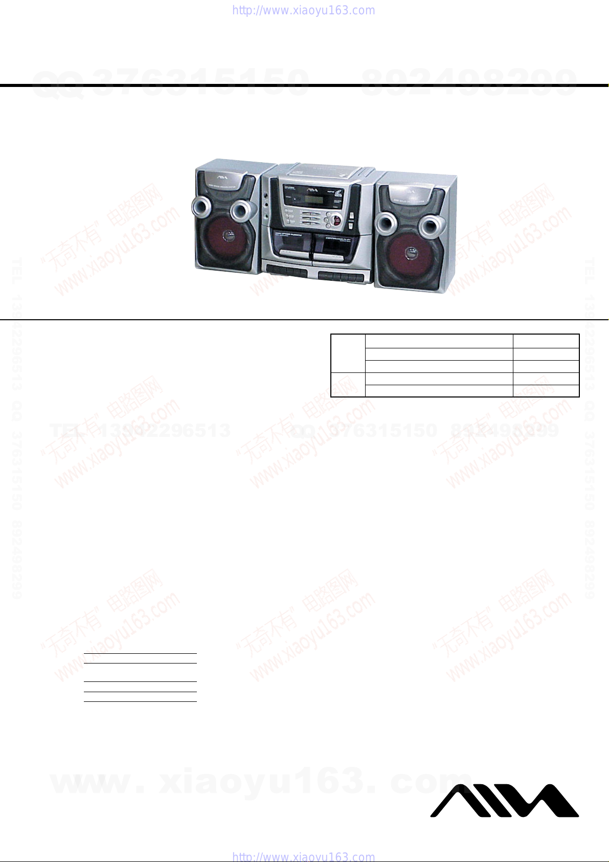
CA-V100
20
GB
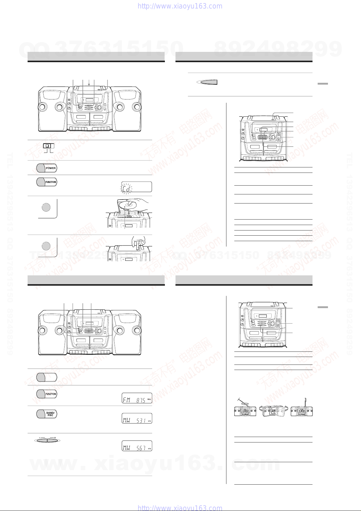
Creating your own
program (Program Play)
You can arrange the playing order of up to
30 tracks on an audio CD.
N
BAND
VOL
FOLDER
MARK
RETURN
DIGEST
KEY KARAOKE
SLOW
OSD PBC
FUNCTION
CD/RADIO
CD
VCD
DISPLAY
(AC ONLY)
POWER
12 3
45
0/10
10
6
789
.,>
FUNCTION
x
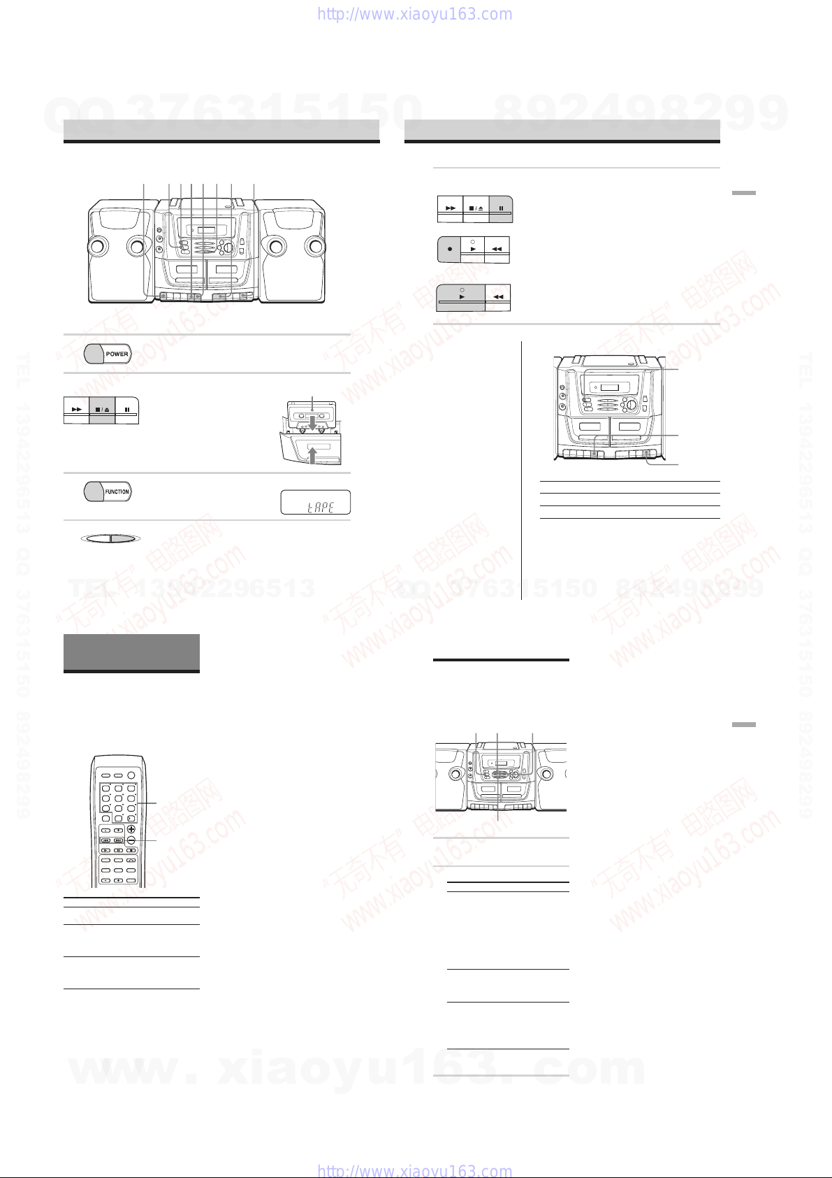
1Press FUNCTION repeatedly to select
the CD function.
2Hold down xin stop mode until “M”
flashes in the display.
3Press the number button for the track
you want to program.
Alternatively, press .or >to
select the track you want to program,
then press x.
After showing the programed track and
its playing order for a few seconds, the
display changes to show the next
playing order.
Repeat this step.
4Hold down xuntil “M” is lit
continuously.
5Press Nto start program play.
To clear the program
In stop mode, hold xuntil “M” disappears
from the display.
You can also clear the program by opening
the CD compartment.
To check the order of tracks
before play
In stop mode, press .or >repeatedly.
Each time you press the button, the track
numbers and their playing order appear in
succession.
To change the current program
Clear the program, and then follow all the
steps again.
Tips
•You can play the same program again, since the
program is saved until you open the CD
compartment.
•You can record your own program. After you
have created the program, insert a blank tape
into deck 1 and press zon deck 1 to start
recording.
Number
buttons
Programed track
Playing order
Next playing order
The Timer
29
GB
The Timer
Falling asleep to music
You can set the player to turn off
automatically after 10, 20, 30, 60, 90, and
120 minutes, allowing you to fall asleep
while listening to music.
.,>POWER
SLEEP
1Play the music source you want.
2Hold down SLEEP until “60” flashes in
the display.
3Press ./>or SLEEP repeatedly
to select the minutes until the player
goes off automatically.
Each time you press >or SLEEP,
the indication changes as follows:
“60” t“90” t“120” t“OFF” t
“10” t“20” t“30” t“60”…
If you press ., the indication
changes in reverse order.
If 4 seconds have passed after you
pressed the button, the minutes in the
display are entered. While the sleep
timer is activated, “z” flashes in the
display.
When the preset time has passed, the
player goes off automatically.
To check the time remaining
until the player is turned off
Hold down SLEEP for about 2 seconds. The
remaining time is displayed for 4 seconds.
To cancel the sleep timer
While the remaining time is flashing in the
display, press SLEEP repeatedly until “OFF”
is displayed.
Note
When you are playing a tape using this function:
If the tape length of one side is longer than the set
time, the player will not go off until the tape
reaches the end.
30
GB
Setting Up
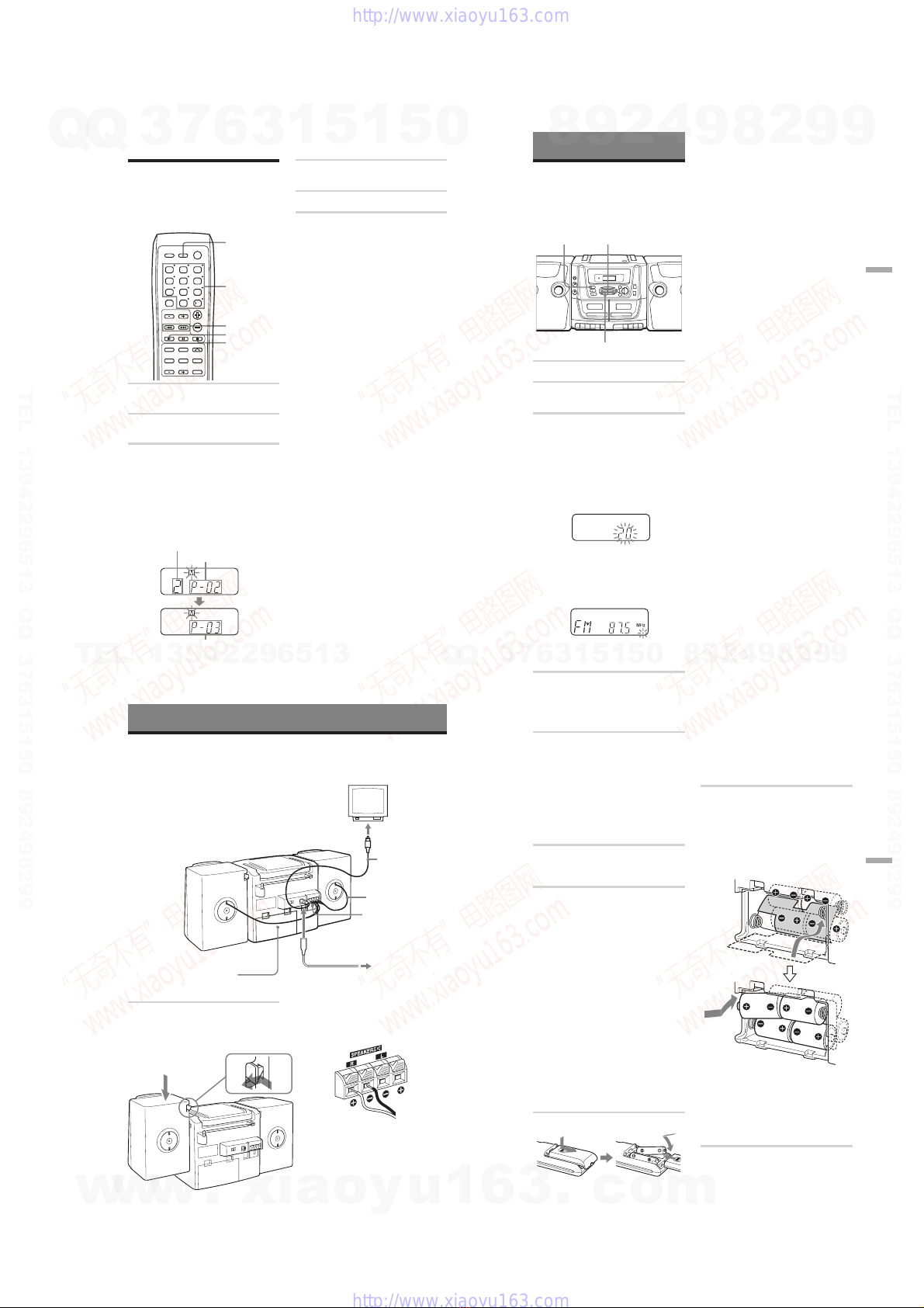
Hooking up the system
Make sure you turn off the power before making any connections.
Right speaker
1Hooking up the speakers
1Align the grooves and slide the
speaker box down until it snaps into
place A.
A
B
2Connect the black wires to Eand the
red wires to eterminals; the right
speaker wires to the R and the left
speaker wires to the L terminals.
Tips
•To detach the speakers, unlock speaker (see
B on the diagram) and slide the speaker
box all the way up and away from the
player.
•Connect the speakers for this unit only to
the speaker terminals of this unit. If you
connect any other speakers or equipment,
malfunction may occur.
Left speaker
TV
1Speaker terminals
Speaker cord
2to the video
input jack
Video cord
3Voltage selector
4to a wall outlet
6
Battery compartment
Setting Up
31
GB
2Connecting the TV
To use the VIDEO CD, connect the TV
equipped with the video input jack in
the following way:
1Connect the supplied video cord to
the VIDEO OUT jack of the player
and the video input jack of the TV.
2Turn on the TV and set the input
mode selector on the TV to the proper
position.
3Adjusting the voltage
Set the voltage selector to your local
power supply.
4Connecting the AC power cord
Insert one end of the supplied AC
power cord to the AC IN socket located
on the rear of the player, and the other
end to the wall outlet.
Changing the MW tuning interval
The MW tuning interval is preset to 9 kHz at
the factory. Perform the following to change
the setting to 10 kHz step.
1Press FUNCTION repeatedly to select the
tuner function.
2While holding down BAND on the player,
press and hold xon the player for about 2
seconds to change the setting to 10 kHz
step.
To set the tuning interval back to 9 kHz step,
follow the same procedure again.
After changing the tuning interval, you need
to reset your MW preset radio stations.
5Inserting batteries into the remote
Insert two R6 (size AA) batteries (not
supplied).
Replacing batteries
With normal use, the batteries should last for
about six months. When the remote no
longer operates the player, replace all the
batteries with new ones.
6Using the player on batteries
Insert eight R20 (size D) batteries (not
supplied) into the battery compartment.
Before inserting the outer four batteries,
close the inner lid as illustrated below.
To use the player on batteries,
disconnect the AC power cord from the
player.
Replacing batteries
Replace the batteries when the OPR/BATT
indicator dims or when the player stops
operating. Replace all the batteries with new
ones. Before you replace the batteries, be
sure to take out the CD from the player.
Note
When you operate the player on batteries, you
cannot turn on the player using the
remote.
w
w
w
.
x
i
a
o
y
u
1
6
3
.
c
o
m
Q
Q
3
7
6
3
1
5
1
5
0
9
9
2
8
9
4
2
9
8
T
E
L
1
3
9
4
2
2
9
6
5
1
3
9
9
2
8
9
4
2
9
8
0
5
1
5
1
3
6
7
3
Q
Q
TEL 13942296513 QQ 376315150 892498299
TEL 13942296513 QQ 376315150 892498299
http://www.xiaoyu163.com
http://www.xiaoyu163.com