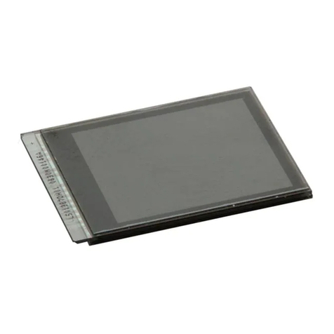
Sharp LS013B7DH07 User manual


Model No. : LS013B7DH07
PAGE
A-
SPEC No. REVISED
No
DATE SUMMARY NOTE
RECORDS OF REVISION
LD-28204A First edition2016/2/22
©Copyright 2016 SHARP All rights reserved

SPEC No.
LD-28204A
MODEL No.
LS013B7DH07
PAGE
1
NOTICE
<<Precautions>>
a) This publication is the proprietary of SHARP and is copyrighted, with all rights reserved.
Under the copyright laws, no part of this publication may be reproduced or transmitted in any form or
by any means, electronic or mechanical for any purpose, in whole or in part, without the express
written permission of SHARP. Express written permission is also required before any use of
this publication may be made by a third party.
b) The application circuit examples in this publication are provided to explain the representative applications of
SHARP's devices and are not intended to guarantee any circuit design or permit any industrial property right
or other rights to be executed. SHARP takes no responsibility for any problems related to any industrial
property right or a third party resulting from the use of SHARP's devices, except for those resulting directly
from device manufacturing processes.
c) When using the products covered herein, please observe the conditions and the precautions written herein.
In no event shall the company be liable for any damages resulting from failure to strictly adhere to these
conditions and precautions.
d) SHARP reserves the right to make changes in the specifications, characteristics, data, materials, structures
and other contents described herein at any time without notice in order to improve design or reliability. Contact
SHARP in order to obtain the latest specification sheets before using any SHARP's device. Manufacturing
locations are also subject to change without notice.
e) The devices in this publication are designed for general electronic equipment use.
f) The appropriate design measures should be taken to ensure reliability and safety when
SHARP's devices are used for equipment such as:
・Transportation control and safety equipment(i.e.,aircraft, trains, automobiles, etc.)
・Traffic signals ・Gas leakage sensor breakers
・Alarm equipment ・Various safety devices etc.
g) SHARP's devices shall not be used for equipment that requires extremely high level of reliability, such as:
・Aerospace equipment ・Military and space applications
・Nuclear power control equipment ・Medical equipment for life support
・Trunk line commucation equipment
SHARP Confidential
technical literature
©Copyright 2016 SHARP All rights reserved©Copyright 2016 SHARP All rights reserved
SPEC No.
LD-28204A
MODEL No.
LS013B7DH07
PAGE
2
h) Contact and consult with a SHARP representative in advance, if there are any questions about the contents
of this publication.
i) Contact a SHARP representative, in advance, when intending to use SHARP’s devices for
any “specific” applications other than those recommended by SHARP.
j) If any problem occurs in relation to the description of this publication, it shall be resolved through discussion
with spirit of cooperation each corporation between each corporation.
k) The ozone-depleting substances are not used.
l) The device in the production is based on RoHS instructions 95/02. And RoHS instructions materials and
chlorinated paraffin are not included intentionally.
[Handling Instructions]
【Handling Precautions】
(1) Treat LCD module in dustless surroundings.
(2) Be sure to turn off the power supply when remove the plugged FPC.
(3) Be careful not to give any physical stress onto the circuit of LCD module when you plug a FPC. Physical
stress will cause a break or worse connection.
(4) Do not touch or scratch the polarizer with items harder than the surface rating or permanent damage can
result.
(5) Since the LCD panel is made of glass, it may break or crack if dropped or bumped on hard surface. Always
handle with care.
(6) Be careful to handle this LCD panel in order to avoid injury yourself as this panel is made of glass and have
sharp edge. When the panel is broken, do not touch the glass. Although the panel is difficult to be scattered,
touching the broken part may hurt your hands.
(7) Since a long contact with water may cause discoloration or spots, wipe it with absorbent cotton or other soft
cloth immediately.
(8) This module contains CGS. Please use appropriate anti-static protection methods for all contact with the
LCD panel and its electrical circuits.
(9) Do not expose to strong ultraviolet rays such as direct sunlight for a long time.
(10) Liquid crystal contained in the panel may leak if the LCD is broken. If LC material should accidently come
in contact with the mouth or eyes rinse with water as soon as possible, following the instructions of the
appropriate MSDS.
SHARP Confidential
technical literature
©Copyright 2016 SHARP All rights reserved©Copyright 2016 SHARP All rights reserved
SPEC No.
LD-28204A
MODEL No.
LS013B7DH07
PAGE
3
(11) Use N2-blower such as ionized nitrogen has anti-electrostatic when you blow dusts on Polarizer.
To clean LCD panel surface, wipe clean with absorbent cotton or soft cloth. If further cleaning is needed,
use IPA(isopropyl alcohol) and wipe clean lightly on surface only.
Do not use organic solvents as it may damage the LCD panel terminal area which uses organic material.
Also, do not directly touch with finger. When the terminals cleaning are needed, those should be wiped by a
soft cloth or a cotton swab without directly touching by hand.
(12) To avoid picture uniformity failure, do not put a seal or an adhesive material on the LCD panel surface.
【Set-Design Precautions】
(1) Disassembly of the LCD panel in any way voids the warranty and may permanently damage the LCD panel.
(2) Do not expose the side of LCD panel and gate driver, etc. on the panel (circuit area outside panel display
area) to light as it may not operate properly. Design that shields the side of LCD panel and gate driver, etc.
from light is required when mounting the LCD module.
(3) Support for the LCD panel should be carefully designed to avoid the outside of stress specification on glass
surface. Be sure to design the cabinet so that the module can be assembled without any extra stress such as
warp or twist.
(4) It causes an irregular display and the defective indication, etc., when always put constant pressure on the
back of the module. Please do not make the structure to press the back of the module.
(5) In case of attaching a cover glass or touch panel to the front surface, use appropriate measures to avoid
degrading optical performance.
(6) To prevent loss of uniformity and prevent the introduction of contamination to the optical path of the LCD
panel, please use fine-pitch filters in the air flow of forced ventilation.
(7) Be sure to follow the absolute maximum rating in the specification. The design should consider the
surrounding temperature, the fluctuating input signal, and tolerance of the electronic parts. Exceeding
values is possible to cause worse characteristic such as burn and/or broken of the parts on LCD module.
(8) Be sure to use LCD module within the recommended Electrical Characteristics and Timing Characteristics of
Input Signals conditions. Operating module out of the recommended range is not guaranteed even if it is in
the absolute maximum rating.
(9) Follow the power, signal, and supply voltage sequence which the specification indicates, regarding on-off
input signal after power on of LCD module.
(10) According to the using application, power circuit protection is recommended at module failure.
(11) When handling LCD modules and assembling them into the cabinet, please avoid long-term storage in the
environment of oxidization or deoxidization gas. The use of materials such as reagent, solvent, adhesive,
resin, etc. which generate these gasses, may cause corrosion and discoloration of the modules.
Do not use the LCD module under such environment.
(12) To avoid picture uniformity failure, do not put a seal or an adhesive material on the LCD panel surface.
SHARP Confidential
technical literature
©Copyright 2016 SHARP All rights reserved©Copyright 2016 SHARP All rights reserved
SPEC No.
LD-28204A
MODEL No.
LS013B7DH07
PAGE
4
(13) Protection film is attached to the module surface to prevent it from being scratched .Peel the film off
slowly, just before the use, with strict attention to electrostatic charges. Blow off 'dust' on the polarizer by
using an ionized nitrogen.
After peeling the protection film off, please do not reattach to the front polarizer. If you reattach and
store it long time, surface of the front polarizer changes in quality and it may cause display
non-uniformity issue.
(14) Panel is susceptible to mechanical stress and such stress may affect the display. Place the LCD panel on
flat surface to avoid stress caused by twist, bend, etc.
(15) To prevent reduction in optical quality and abnormal display, avoid exposure and contamination of the
LCD panel from epoxy resin (mine system curing agent) that comes out from the material and the
packaging material used for the set side, the silicon adhesive (dealcoholization system and oxime system),
and the tray blowing agents ( azo-compound), etc. Please confirm LCD panel compatibility with materials
employed in your manufacturing and shipping processes.
(16) Since the LCD panel is made of glass, it may break or crack if dropped or bumped on hard surface.
Always handle with care.
(17) Please design part arrangement to consider the heat dissipation not to change the local temperature for
module.
(18) There are metal patterns on the outer edge of FPC.
Please design your housing not to contact the conductive part.
(19) This product is not water-proof and dust-proof structure.
(20) As this LCD module is composed electronic circuits, it is sensitive to electrostatic discharge of 200V or
more. Handle with care using cautions for the followings:
O
perators
Operators must wear anti-static wears to prevent electrostatic charge up to and discharge from
human body.
Equipment and containers
Process equipment such as conveyer, soldering iron, working bench and containers may possibly
generate electrostatic charge up and discharge. Equipment must be grounded through 100Mohms
resistance. Use ion blower.
Floor
Floor plays an important role in leaking static electricity generated in human body or equipment. If
the floor is made of insulated material (such as polymer or rubber material), such static electricity
may charge. Proper measure should be taken to avoid static electricity charge (electrostatic earth:
100Mohms).There is a possibility that the static electricity is charged to them without leakage in case
of insulating floor, so the electrostatic earth: 100Mohms should be made.
SHARP Confidential
technical literature
©Copyright 2016 SHARP All rights reserved©Copyright 2016 SHARP All rights reserved

SPEC No.
LD-28204A
MODEL No.
LS013B7DH07
PAGE
5
Humi
dity
Humidity in work area relates to surface resistance of the persons or objects that generate
electrostatics, and it can be manipulated to prevent electrostatic charge. Humidity of 40% or lower
increases electrostatic earth resistance and promotes electrostatic charging. Therefore, the
humidity in the work area should be kept above 40%. Specifically for film peeling process or
processes that require human hands, humidity should be kept above 50% and use electricity removal
blower.
Transportation/Storage
Containers and styroform used in transporation and storage may charge electrostatic (from friction
and peeling) or electrostatic charge from human body, etc. may cause containers and styroform to
have induced charge. Proper electrostatic measure should be taken for containers and storage
material.
【Operation Precautions】
(1) Do not use polychloroprene (CR) with LCD module. It will generate chlorine gas, which will damage the
reliability of the connection part on LCD panel.
(2) Be sure to use LCD module within the recommended operating conditions. Operating module out of the
recommended range is not guaranteed even if it is in the absolute maximum rating.
(3) When handling LCD modules and assembling them into cabinets, please avoid long-term storage in the
environment of oxidization or deoxidization gas. The use of materials such as reagent, solvent,
adhesive, resin, etc. which generate these gasses, may cause corrosion and discoloration of the modules.
Do not use the LCD module under such environment.
(3) To prevent reduction in optical quality and abnormal display, avoid exposure and contamination
of the LCD panel from epoxy resin (amine system curing agent) that comes out from the material
and the packaging material used for the set side, the silicon adhesive (dealcoholization system
and oxime system), and the tray blowing agents ( azo-compound), etc.
Please confirm LCD panel compatibility with materials employed in your manufacturing
and shipping processes.
(4) If stored at the temperatures lower than the rated storage temperature, the LC may freeze
and it may cause LCD panel damage. And If stored at the temperatures higher than
the rated storage temperature, the LC will lose its characteristics, and it cannot recover.
Please keep it at near room temperature.
(5) Do not operate the LCD panel under outside of electrical specification.
Otherwise LCD panel may be damaged.
(6) Do not use the LCD panel under outside of specified driving timing chart.
Otherwise LCD panel may not have proper picture quality.
SHARP Confidential
technical literature
©Copyright 2016 SHARP All rights reserved©Copyright 2016 SHARP All rights reserved
SPEC No.
LD-28204A
MODEL No.
LS013B7DH07
PAGE
6
(7) A still image should be displayed less than two hours, if it is necessary to display still image
longer than two days, display image data must be refreshed
in order to avoid sticking image on LCD panel.
(8) If LCD module takes a static electricity, as the display image which is written into pixel memory might
not be displayed, Data update should be executed frequently.
(9) It is neither a breakdown nor a defective indication though very slight change in black level might be
periodically seen in a black part on the black display image according to the source of light (angle of the
luminance and the source of light).
(10) Be sure to follow the absolute maximum rating in the specification. The design should consider the
surrounding temperature, the fluctuating input signal, and tolerance of the electronic parts. Exceeding
values is possible to cause worse characteristic such as burn and/or broken of the parts on LCD module.
(11) Follow the power, signal, and supply voltage sequence which the specification indicates, regarding on-off
input signal after power on of LCD module.
(12) According to the using application, power circuit protection is recommended at module failure.
(13) Nature of dew consideration prevention is necessary when LCD is used for long time under
high-temperature and high-humidity
SHARP Confidential
technical literature
©Copyright 2016 SHARP All rights reserved©Copyright 2016 SHARP All rights reserved
SPEC No.
LD-28204A
MODEL No.
LS013B7DH07
PAGE
7
[Precautions for Storage]
(1) After opening the package, do not leave the LCD panel in direct sun or under strong ultraviolet ray.
Store in the dark place.
(2) In temperature lower than specified rating, liquid crystal material will coagulate. In temperature higher
than specified rating, it will liquefies. In either condition, the liquid crystal may not recover its original
condition. Store the LCD panel in at or around room temperature as much as possible.
Also, storing the LCD panel in high humidity will damage the polarizer.
Store in normal room temperature as much as possible.
(3) Keeping Method
a. Don't keeping under the direct sunlight. b. Keeping in the tray under the dark place.
SHARP Confidential
technical literature
©Copyright 2016 SHARP All rights reserved©Copyright 2016 SHARP All rights reserved
SPEC No.
LD-28204A
MODEL No.
LS013B7DH07
PAGE
8
[Other Notice]
(1) Operation outside specified environmental conditions cannot be guaranteed.
(2) As power supply (VDD-GND、VDDA-GND) impedance is lowered during use, bus controller should be
inserted near LCD module as much as possible.
(3) Polarizer is applied over LCD panel surface. Liquid crystal inside LCD panel deteriorates with ultraviolet
ray. The panel should not be left in direct sun or under strong ultraviolet ray for prolonged period of time
even with the polarizer.
(4) Disassembling the LCD module will cause permanent damage to the module. Do not disassemble the
module.
(5) If LCD panel is broken, do not ingest the liquid crystal from the broken panel. If hand, leg or clothes
come in contact with liquid crystal, wash off immediately with soap. If mouth or eyes come in contact with
liquid crystal, rinse with water as soon as possible, following the instructions of the appropriate MSDS.
(6) ODS (specific chlorofuorocarbon, specific halon, 1-1-1 trichloroethane, carbon tetrachloride) are not used
or contained in material or all production processes of this product.
(7) Observe all other precautionary requirements in handling general electronic components.
Discarding liquid crystal modules
Follow the regulations when LCD module is scrapped. The government you stay may have some regulations
about it.
LCD Panel : Dispose of as glass waste. This LCD module contains no harmful
substances.
The liquid crystal panel contains no dangerous or harmful substances.
This liquid crystal panel contains only an extremely small amount of liquid
crystal (approximately 100mg) and therefore it will not leak even if the
panel should break.
Its median lethal dose (LD50) is greater than 2,000 mg/kg and a
mutagenetic (Aims test: negative) material is used.
SHARP Confidential
technical literature
©Copyright 2016 SHARP All rights reserved©Copyright 2016 SHARP All rights reserved
SPEC No.
LD-28204A
MODEL No.
LS013B7DH07
PAGE
9
Contents
1. Outline ............................................................................................................................................................ 10
2. Characteristics .............................................................................................................................................. 10
3. Mechanical Specification .............................................................................................................................. 10
4. Input terminal names and functions ........................................................................................................... 11
6. Electrical characteristics
.............................................................................................................................. 13
7. Optical characteristics .................................................................................................................................. 24
8. Pin Assignment ............................................................................................................................................. 26
9. Display Qualities ........................................................................................................................................... 27
10. External capacitors ..................................................................................................................................... 27
11. Marking ......................................................................................................................................................... 28
12. Packaging .................................................................................................................................................... 29
13. Reliability Test Conditions ......................................................................................................................... 31
14. Outline dimensions ..................................................................................................................................... 32
SHARP Confidential
technical literature
©Copyright 2016 SHARP All rights reserved©Copyright 2016 SHARP All rights reserved

SPEC No.
LD-28204A
MODEL No.
LS013B7DH07
PAGE
10
1. Outline
This TFT-LCD module is a reflective active-matrix with slightly transmissive
memory liquid crystal display module with CG silicone thin film transistor.
Module outline is indicated in fig 14-1.
2. Characteristics
・ A reflective active-matrix with slightly transmissive panel of white and black
・ 1.26” screen has 144 x 168 resolusion. (24192 pixels stripe array)
・ Display control by serial data signal communication.
・ Arbitrary line data renewable.
・ 1bit internal memory for data storage within the panel.
・ Thin, light-weight and compact module with monolithic technology.
・ Super low power consumption TFT panel.
3. Mechanical Specification
Table 3-1 Mechanical Specification
Item Specification unit
Screen size 3.2 (1.26”) cm
Active Area 20.88 (Horizontal) × 24.36 (Vertical) mm
Dot configuration 144 (Horizontal) × 168 (Vertical) Dot
Dot pitch 0.145 (Horizontal) × 0.145 (Vertical) mm
Pixel Array Stripe Array -
Outline Dimension 24.68 (W) × 30.00 (H) × 0.745 (D) mm
Mass 1.1 (max) g
Surface Hardness 3H Pencil hardness
Surface treatment AG
(Note) Detail dimension and tolerance are shown in fig. 14-1
SHARP Confidential
technical literature
©Copyright 2016 SHARP All rights reserved©Copyright 2016 SHARP All rights reserved
SPEC No.
LD-28204A
MODEL No.
LS013B7DH07
PAGE
11
4. Input terminal names and functions
Table4-1 Pin description
Terminal Symbol I/O Configurations Function Remark
1 SCLK INPUT NoPull Serial clock signal
2 SI INPUT NoPull Serial data input signal
3 SCS INPUT NoPull Chip select signal ( Active of Hi )
4 EXTCOMIN INPUT NoPull External COM inversion signal input
(Input Square wave or connecttheVSS)
【Note 4-2】
5 DISP INPUT NoPull Display ON/OFF signal 【Note 4-1】
6 NC - - No connection
7 VDDA POWER -Power supply (Analog)
8 VDD POWER -Power supply (Digital)
9 EXTMODE INPUT NoPull Control mode of COM inversion is select terminal
( connect the VDD or VSS )
【Note 4-2】
10 VSS GND -GND (Digital)
11 VSSA GND -GND (Analog)
※ NoPull : Neither Pulled up or Pulled down.
【Note 4-1】 The display ON/OFF signal is only for display. Data in the memory will be saved at the time of
ON/OFF.
When it’s ”Hi”, data in the memory will display, when it’s ”Lo”, white color will diaplay and data in
the memory will be saved.
【Note 4-2】 When EXTMODE is ”Hi”, EXTCOMIN signal is enable.
When EXTMODE is ”Lo” ,serial input flag is enable.
“Hi”mode ; connect the EXTMODE to VDD,
”Lo” mode ; connect the EXTMODE and EXTCOMIN to VSS.
4-1) Recommended Circuit
< EXTMODE=”Lo” > < EXTMODE=”Hi” >
COM Signal Serial Flag Input External COM Signal Input
Figure 4-1 Recommended circuit
1 SCLK 1 SCLK
2 SI 2 SI
3 SCS 3 SCS
4 EXTCOMIN 4 EXTCOMIN
5 DISP 5 DISP
6 NC 6 NC
7 VDDA 7 VDDA
8 VDD 8 VDD
9 EXTMODE 9 EXTMODE
10 VSS 10 VSS
11 VSSA 11 VSSA
SHARP Confidential
technical literature
©Copyright 2016 SHARP All rights reserved©Copyright 2016 SHARP All rights reserved
SPEC No.
LD-28204A
MODEL No.
LS013B7DH07
PAGE
12
5. Absolute Maximum Rating
Table5-1 Absolute Maximum Rating ( VSS=0V , VSSA=0V )
Item Symbol MIN. MAX. Unit Remark
Power
supply
voltage
Analog VDDA -0.3 +3.6 V
Logic VDD -0.3 +3.6 V [Note 5-1]
Input signal voltage(high) VDD V [Note 5-2]
Input signal voltage(low) -0.3 V
Strage Temperature Tstg -30 +80 ℃ [Note 5-3,4]
Operation Temperature
(at panel surface)
Topr -20 +70 ℃ [Note 5-4,5]
[Note 5-1] Applies to EXTMODE.
[Note 5-2] Applies to SCLK, SI, SCS, DISP, EXTCOMIN.
[Note 5-3] Do not exceed this temperature in any parts of module.
[Note 5-4] Humidity 95%RH Max.(Ta ≦ 40℃)
Attention should be paid to static electricity
Maximum wet bulb temperature is 39℃ or lower. No condensation is allowed.
Cndensation will cause electeical leak and may cause the module to not meet this specification.
[Note 5-5] Operating temperature is the temperature that guarantees only for the operation.
For contrast, response time, and other display quality determination, use Ta=+25℃.
SHARP Confidential
technical literature
©Copyright 2016 SHARP All rights reserved©Copyright 2016 SHARP All rights reserved
SPEC No.
LD-28204A
MODEL No.
LS013B7DH07
PAGE
13
6. Electrical characteristics
6-1) TFT LCD panel drive
Table6-1 Recommended operating Condition VSS=0V、VSSA=0V、Ta=+25℃
Item symbol MIN. TYP. MAX. Unit Remark
Power supply Analog VDDA +2.7 +3.0 +3.3 V
Logic VDD +2.7 +3.0 +3.3 V [Note 6-1]
Input signal voltage Hi VIH +2.70 +3.00 *VDD V [Note 6-2]
Lo VIL VSS VSS VSS+0.1 V
*It can be operated below VDD voltage, however, operation around 3V is recommended.
[Note 6-1] Applies to EXTMODE=”Hi”
[Note 6-2] Applies to SCLK, SI, SCS, DISP, EXTCOMIN.
SHARP Confidential
technical literature
©Copyright 2016 SHARP All rights reserved©Copyright 2016 SHARP All rights reserved

SPEC No.
LD-28204A
MODEL No.
LS013B7DH07
PAGE
14
6-2) Power supply sequence
※Refer to timing chart and AC timing characteristics for detail
※1 ③ and ④ may be opposite (however, TCOM polarity inversion will not occur even with EXTCOMIN
between DISP=”Lo”. Also, when DISP and EXTCOMIN are simultaneously started up, allow 30us or
more before SCS starts up (It may be less than 60us).
※2 Setting value for pixel memory initialization
SCS=Driving accordingly to clear pixel internal memory method (use all clear flag or write all screen white)
S1=M2 (all clear flag) = “Hi” or write white
SCLK: Normal Driving
[Remark] Precaustions at ehte time of power on and power off.
Remark 1)When power on , VDDand VDDA are same timem or VDD should be faster than the VDDA.
Remark 2) When power off, VDD and VDDA are same time or VDDA shoud be faster than the VDD.
①②
③※1④※1⑤⑥⑦
VDD/VDDA(5V)
GND GND
DISP
GND GND
EXTCOMIN
GND GND
SCS
GND
※2※2
GND
Others
GND
※2※2
GND
Normal operation
Normal operation
Normal operation
T1
Off sequenceNormal operation
T2 T3 T4 T5 T6 T7
On Sequence
[ON Sequence]
(1) 3V rise time (depends on IC)
(2) Pixel memory initialization
T2: 1time or more Initialize with M2 (all clear flag) or write all screen white
(3) Release time for initialization of TCOM latch T3: 30us or more
Time required to release COM related latch circuit initialization which is initializing using DISP signals
(4) TCOM polarity initialization time T4: 30us or more
Time required initializing TCOM polarity accordingly to EXTCOMIN input
[Normal Operation]
Duration of normal driving
[Off Sequence]
(5) Pixel memory initialization time T5: 1time or more
(6) VA, VB, VCOM initialization time T6: 30us or more
SHARP Confidential
technical literature
©Copyright 2016 SHARP All rights reserved©Copyright 2016 SHARP All rights reserved
SPEC No.
LD-28204A
MODEL No.
LS013B7DH07
PAGE
15
6-3) Input signal characteristics
Table6-3-1 Recommend Operating Cunditions and DC Characteristics
VDDA=+3.0V、VDD=+3.0V、VSS=0V、VSSA=0V、Ta=25℃
Item Symbol MIN TYP MAX Unit Remark
Frame frequency fSCS 57 60 66 Hz When EXTMODE = Lo
【Note 6-3】
- - 66 Hz When EXTMODE = Hi
【Note 6-3】
Clock frequency fSCLK 1 1.1 MHz
Vertical Interval tV 15.15 - 17.54 ms
COM Frequency fCOM 28.5 - 33 Hz
【Note 6-3】 Please use afram frequency in the range where there are no problems with the display quality.
Table 6-3-2 Input Signal timing Parameters VDDA=+3.0V、VDD=+3.0V、VSS=0V、VSSA=0V、Ta=25℃
Item Symbol MIN TYP MAX Unit Remark
SCS Rising time trSCS - - 50 ns
SCS Falling Time tfSCS - - 50 ns
SCS High duration twSCSH 168 - - us
22.54 - - us
SCS Low duration twSCSL 6 - - us
SCS set up time tsSCS 6 - - us
SCS hold time thSCS 2 - - us
SI Rising time trSI - - 50 ns
SI Folling time tfSI - - 50 ns
SI set up time tsSI 250 - - ns
SI hold time thSI 350 - - ns
SCLK Rising time trSCLK - - 50 ns
SCLK Folling time tfSCLK - - 50 ns
SCLK High duration twSCLKH 404.55 450 - ns
SCLK Low duration twSCLKL 404.55 450 - ns
EXTCOMIN signal frequency fEXTCOMIN 57 60 66 Hz
EXTCOMIN signal rising time trEXTCOMIN - - 50 ns
EXTCOMIN signal folling time twEXTCOMIN - - 50 ns
EXTCOMIN signalHigh duration thlEXTCOMIN 2 us
DISP Rising time trDISP - - 50 ns
DISP Folling time tfDISP - - 50 ns
SHARP Confidential
technical literature
©Copyright 2016 SHARP All rights reserved©Copyright 2016 SHARP All rights reserved
SPEC No.
LD-28204A
MODEL No.
LS013B7DH07
PAGE
16
6-4) Signal Timing
COM signal serial input (EXTMODE=”Lo”)
※SCS,SI,SCLK、DISP、EXTCOMIN: 3V input voltage
Figure 6-4 Signal Timing
SHARP Confidential
technical literature
©Copyright 2016 SHARP All rights reserved©Copyright 2016 SHARP All rights reserved

SPEC No.
LD-28204A
MODEL No.
LS013B7DH07
PAGE
17
6-5) Power consumption
Table6-5 Current Consumption Ta=25℃,SCS SCLK,SI,DISP,EXTCOMIN=+3V ,VDD=+3V, VDDA=+3V
Operating Mode Power consumption Min Typ Max unit Remark
Condition 1 Display mode
(no display data update)
Display pattern : Black display
- 25 125 uW [Note 6-4]
Condition 2 Data update mode
with display update 1Hz
(1fram/sec)
Display pattern : Vertical stripe display
- 35 150 uW [Note 6-5]
[Note 6-4]
a) SCLK=Lo 、 SCS=Lo 、 SI=Lo (after writed Black data)
b) It measures after writed Black data.
[Note 6-5]
a) fSCS=1.0Hz (Except in the time of writing, it is set to SCS=Lo .)
b) SCLK=Lo 、 SCS=Lo 、 SI=Lo (after writed Vertical stripe data)
Common inversion with VDD=3.0V、VDDA=3.0V、fCLK=1.0MHz、EXTMODE=VDD、EXTCOMIN=60Hz
( Common Note)
This is value in steady condition, not the falue of peak power at the time of COM operation.
Some marging for power supply is recommended.
We recommend capacitor for VDD and VDDA.
(If VDD and VDDA are on separate systems, we recommend capacitor for each.)
Formula for computation
(
Ivd
d + Ivdda )[uA] × 3[V]
*LC inversion : LC material is needed alternative polarity driving as changing timing which should be 60Hz.
( LC inversion frequency 60Hz is COM frequency 30Hz)
as shown fig6-5.
F
iqu
re 6-5 COM inversion frequency
【Remark 6-6】 This is value in steady condition, not the falue of peak power at the time of COM operation.
Some marging for power supply is recommended. We recommend capacitor for VDD and VDDA.
(If VDD and VDDA are on separate systems, we recommend capacitor for each.)
COM inversion frequency
Hi
LC inversion frequency
60Hz(16.7ms)
Lo
SHARP Confidential
technical literature
©Copyright 2016 SHARP All rights reserved©Copyright 2016 SHARP All rights reserved
SPEC No.
LD-28204A
MODEL No.
LS013B7DH07
PAGE
18
6-6) Input Signal Timing Chart
6-6-1 Data update mode (1 line)
Updates data of only one specified line. (M0=”Hi”、M2=”Lo”)
Figure 6-6 Data update mode by 1line
M0: Mode flag. Set for “Hi”. Data update mode (Memory internal data update)
When “Lo”, display mode (maintain memory internal data).
M1: Frame inversion flag.
When “Hi”, outputs VCOM=”Hi”, and when “Lo”, outputs VCOM=”Lo”.
When EXTMODE=”Hi”, it can be “Hi” or “Lo”.
M2: All clear flag.
Refer to 6-6-4) All Clear Mode to execute clear.
DUMMY DATA: Dummy data. It can be “Hi” or “Lo” (“Lo” is recommended.)
※For gate line address setting, refer to 6-7) Input Signal and Display.
※M1: Frame inversion flag is enaled when EXTMODE=”Lo”.
※When SCS becomes “Lo”, M0 and M2 are cleared.
※ Data write period
Data is being stored in 1st latch block of binary driver on panel.
※ Data transfer period
Data written in 1st latch is being transferred (written) to pixel internal memory circuit.
SHARP Confidential
technical literature
©Copyright 2016 SHARP All rights reserved©Copyright 2016 SHARP All rights reserved
Table of contents
Other Sharp Control Unit manuals

Sharp
Sharp ND-AH330H User manual

Sharp
Sharp NU-JC400B User manual

Sharp
Sharp NB-JD575 User manual

Sharp
Sharp LQ197V3DZ81 Application guide

Sharp
Sharp ND-RK270 User manual

Sharp
Sharp NU-JC375 User manual

Sharp
Sharp NU-JC415B User manual

Sharp
Sharp NU-JC410 User manual

Sharp
Sharp LS013B7DH01 User manual

Sharp
Sharp LS013B7DH01 User manual

Sharp
Sharp MX-PEX1 User manual

Sharp
Sharp PN-ZB03 Series User manual

Sharp
Sharp NU-AK300 User manual

Sharp
Sharp NU-JC365B User manual

Sharp
Sharp ND-123UJF Guide

Sharp
Sharp ND-AH330 User manual

Sharp
Sharp LQ058T5DRQ1 User manual

Sharp
Sharp JW Series Instruction manual

Sharp
Sharp NB-JD580 User manual

Sharp
Sharp ND-AK270 User manual