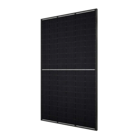
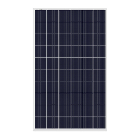
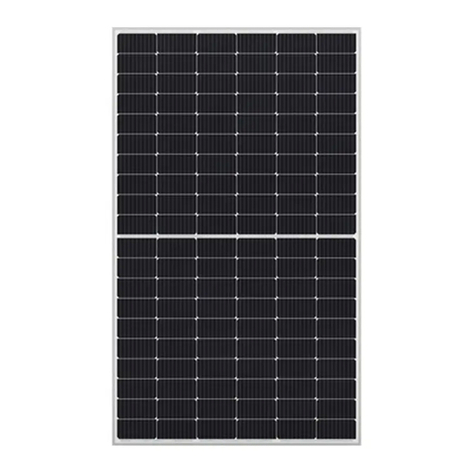
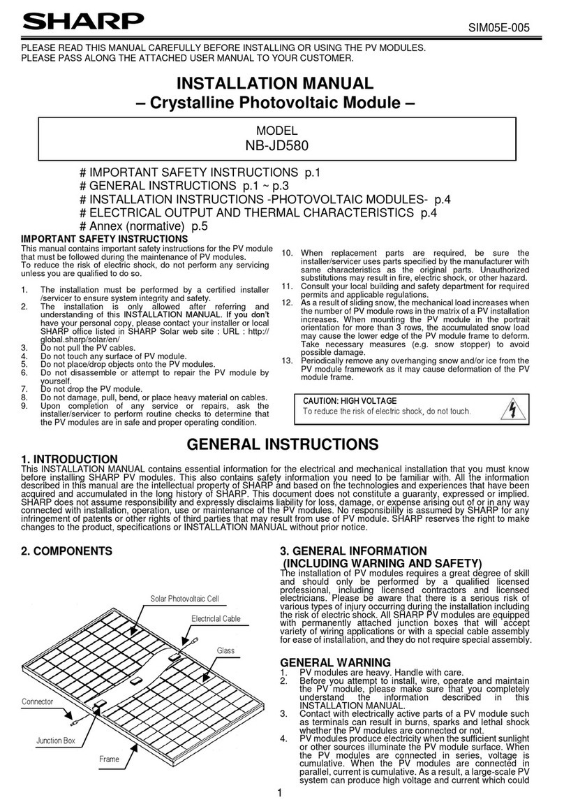
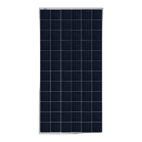
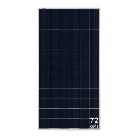
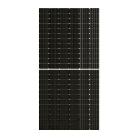
Sharp NU-JC410 User manual

SIM02E-011
1
PLEASE READ THIS MANUAL CAREFULLY BEFORE INSTALLING OR USING THE PV MODULES.
PLEASE PASS ALONG THE ATTACHED USER MANUAL TO YOUR CUSTOMER.
INSTALLATION MANUAL
– Crystalline Photovoltaic Module –
# IMPORTANT SAFETY INSTRUCTIONS p.1
# GENERAL INSTRUCTIONS p.1 ~ p.3
# INSTALLATION INSTRUCTIONS -PHOTOVOLTAIC MODULES- p.4
# ELECTRICAL OUTPUT AND THERMAL CHARACTERISTICS p.4
# A ex ( ormative) p.5
IMPORTANT SAFETY INSTRUCTIONS
This ma ual co tai s importa t safety i structio s for the PV module
that must be followed duri g the mai te a ce of PV modules.
To reduce the risk of electric shock, do ot perform a y servici g
u less you are qualified to do so.
1. The i stallatio must be performed by a certified i staller
/servicer to e sure system i tegrity a d safety.
2. The i stallatio is o ly allowed after referri g a d
u dersta di g of this INSTALLATION MANUAL. If you do ’t
have your perso al copy, please co tact your i staller or local
SHARP office listed i SHARP Solar web site : URL : http://
global.sharp/solar/e /
3. Do ot pull the PV cables.
4. Do ot touch a y surface of PV module.
5. Do ot place/drop objects o to the PV modules.
6. Do ot disassemble or attempt to repair the PV module by
yourself.
7. Do ot drop the PV module.
8. Do ot damage, pull, be d, or place heavy material o cables.
9. Upo completio of a y service or repairs, ask the
i staller/servicer to perform routi e checks to determi e that
the PV modules are i safe a d proper operati g co ditio .
10. Whe replaceme t parts are required, be sure the
i staller/servicer uses parts specified by the ma ufacturer with
same characteristics as the origi al parts. U authorized
substitutio s may result i fire, electric shock, or other hazard.
11. Co sult your local buildi g a d safety departme t for required
permits a d applicable regulatio s.
12. As a result of slidi g s ow, the mecha ical load i creases whe
the umber of PV module rows i the matrix of a PV i stallatio
i creases. Whe mou ti g the PV module i the portrait
orie tatio for more tha 3 rows, the accumulated s ow load
may cause the lower edge of the PV module frame to deform.
Take ecessary measures (e.g. s ow stopper) to avoid
possible damage.
13. Periodically remove a y overha gi g s ow a d/or ice from the
PV module framework as it may cause deformatio of the PV
module frame.
GENERAL INSTRUCTIONS
. INTRODUCTION
This INSTALLATION MANUAL co tai s esse tial i formatio for the electrical a d mecha ical i stallatio that you must k ow
before i stalli g SHARP PV modules. This also co tai s safety i formatio you eed to be familiar with. All the i formatio
described i this ma ual are the i tellectual property of SHARP a d based o the tech ologies a d experie ces that have bee
acquired a d accumulated i the lo g history of SHARP. This docume t does ot co stitute a guara ty, expressed or implied.
SHARP does ot assume respo sibility a d expressly disclaims liability for loss, damage, or expe se arisi g out of or i a y way
co ected with i stallatio , operatio , use or mai te a ce of the PV modules. No respo sibility is assumed by SHARP for a y
i fri geme t of pate ts or other rights of third parties that may result from use of PV module. SHARP reserves the right to make
cha ges to the product, specificatio s or INSTALLATION MANUAL without prior otice.
2. COMPONENTS
3. GENERAL INFORMATION
(INCLUDING WARNING AND SAFETY)
The i stallatio of PV modules requires a great degree of skill
a d should o ly be performed by a qualified lice sed
professio al, i cludi g lice sed co tractors a d lice sed
electricia s. Please be aware that there is a serious risk of
various types of i jury occurri g duri g the i stallatio i cludi g
the risk of electric shock. All SHARP PV modules are equipped
with perma e tly attached ju ctio boxes that will accept
variety of wiri g applicatio s or with a special cable assembly
for ease of i stallatio , a d they do ot require special
assembly.
GENERAL WARNING
1. PV modules are heavy. Ha dle with care.
2. Before you attempt to i stall, wire, operate a d mai tai
the PV module, please make sure that you completely
u dersta d the i formatio described i this
INSTALLATION MANUAL.
3. Co tact with electrically active parts of a PV module such
as termi als ca result i bur s, sparks a d lethal shock
whether the PV modules are co ected or ot.
4. PV modules produce electricity whe the sufficie t su light
or other sources illumi ate the PV module surface. Whe
the PV modules are co ected i series, voltage is
cumulative. Whe the PV modules are co ected i
parallel, curre t is cumulative. As a result, a large-scale PV
MODEL
NU-JC410
CAUTION: HIGH VOLTAGE
To reduce the risk of electric shock, do not touch.
Solar Photovoltaic Cell
Junction Box
Glass
Frame
Connector
Electriclal Cable

SIM02E-011
2
system ca produce high voltage a d curre t which could
prese t a i creased hazard a d may cause serious i jury
or death.
5. Do ot co ect the PV modules directly to the loads such
as motor si ce the variatio of the output power depe di g
o the solar irradiatio causes damage for the co ected
motor.
1: I the case of a brushless motor, the lock fu ctio
becomes active a d the hall IC is most likely to be
damaged.
2: I the case of a brush type motor, the coil is most likely
to be damaged.
6. I case of s ow build-up, s ow would slide easier o the
smooth surface of the PV module tha other parts of the
roof. S ow may sudde ly slide, fall off the roof a d hit
earby objects/areas. Take preve tive measures (e.g.
s ow stopper) whe there is possible risk such case would
cause a i jury or a damage.
GENERAL SAFETY
1. Co sult local codes a d other applicable laws co cer i g
required permits o regulatio s for i stallatio a d
i spectio requireme ts.
2. Before i stalli g a PV module, co tact appropriate
authorities to determi e permit, i stallatio a d i spectio
requireme ts that should be followed.
3. I stall PV modules a d grou d frames i accorda ce with
applicable rules a d regulatio s.
4. PV modules should be i stalled a d mai tai ed by
qualified perso el. O ly i staller/servicer perso el
should have access to the PV module i stallatio site.
5. No matter where the PV modules are i stalled, either roof
mou ted co structio or a y other type of structures above
the grou d, appropriate safety practices should be
followed a d required safety equipme t should be used i
order to avoid possible safety hazards. Note that the
i stallatio of some PV modules o roofs may require the
additio of fireproofi g, depe di g o local buildi g/fire
codes.
6. I the case that the PV modules are o -i tegral type, the
PV module is to be mou ted over a fire resista t roof.
7. Use PV modules with the same cell size withi series.
8. Follow all safety precautio s of other compo e ts that are
used i the system.
9. I order to avoid a risk of i jury or electrical shock, do ot
allow a yo e to approach the PV module if the perso has
little k owledge o PV module or o the measures that
should be take whe PV modules are damaged.
10. Do ot shade portio s of the PV module surface from the
su light for a lo g time. The shaded cell may become hot
(hot spot phe ome o ) which results i solder joi ts
peeli g off. Shadi g causes drop i ge erated power
a d/or operatio failure of the PV modules.
11. Do ot clea the glass surface with chemicals. Do ot let
water collect o the glass surface for a lo g time. This
creates a risk of white effloresce ce (glass disease) which
may result i the deterioratio of e ergy ge eratio .
12. Do ot i stall the PV module horizo tally. It may cause dirt
or white effloresce ce (glass disease) due to water.
13. Do ot cover the water drai gap of the frame. There is a
risk of frost damage whe the frame is filled with water
cumulatio .
14. If there is a risk of slidi g s ow, a appropriate measure
has to be take so that PV module frames o lower edge
of PV modules will ot be damaged.
15. Do ot expose PV module to su light co ce trated with
mirrors, le ses or similar mea s.
16. Tur off i verters a d circuit breakers immediately, should
a problem occur.
17. I case the glass surface of a PV module is broke , wear
goggles a d tape the glass to keep the broke pieces i
place.
18. A defective PV module may ge erate power eve if it is
removed from the system. It may be da gerous to ha dle
the PV module while exposed to su light. Place a defective
PV module i a carto so PV cells are completely shaded.
19. I case of series co ectio , the maximum ope circuit
voltage must ot be greater tha the specified maximum
system voltage. The voltage is proportio al to the umber
of modules i series. I case of parallel co ectio , please
be sure to take proper measure (e.g. fuse for protectio of
PV module a d cable from over curre t, a d/or blocki g
diode for preve tio of u bala ced stri gs voltage) to block
the reverse curre t flow. The curre t may easily flow i a
reverse directio .
20. Keep PV modules away from childre .
HANDLING SAFETY
1. Do ot cause a excessive load o the surface of PV
module or twist the frame. The glass surface or cells i the
PV module ca easily break.
2. Do ot sta d or step o the PV module. The surface glass
of PV module is slippery. Besides, the weight may cause
PV module damage.
3. Do ot hit or put excessive load o the glass or back sheet.
The PV cell is very thi a d ca be easily broke .
4. Do ot scratch or hit at the back sheet. The back sheet is
vul erable.
5. Do ot damage the ju ctio boxes or do ot pull the cables.
The ju ctio boxes ca crack a d break.
6. Never touch ju ctio box or the e d of output cables with
bare ha ds whe the PV module is irradiated. Cover the
surface of PV module with cloth or other suitable
sufficie tly opaque material to isolate the PV module from
i cide t light a d wear rubber gloves whe ha dli g the
wires to avoid electric shock.
7. Do ot scratch the output cable or be d it with force. The
i sulatio of output cable ca break a d may result i
electricity leakage or shock.
8. Do ot pull the output cable excessively. The output cable
may u plug a d cause electricity leakage or shock.
9. Do ot drill holes i the frame. It may compromise the
frame stre gth a d cause corrosio .
10. Do ot scratch the i sulatio coati g of the frame (except
for grou di g co ectio ). It may cause corrosio of the
frame or compromise the framework stre gth.
11. Do ot touch the PV module with bare ha ds. The frame
of PV module has sharp edges a d may cause i jury.
12. Do ot drop PV module or allow objects to fall dow o the
PV module.
13. Do ot co ce trate su light artificially o the PV module.
14. Do ot hold the PV module o o e side. The frame may
be d or twist. Hold the PV module at opposite sides.
INSTALLATION SAFETY
1. Always wear protective head gear, i sulati g gloves a d
safety shoes (with rubber soles). Do ot wear metallic
jewelry to preve t electric shock duri g i stallatio .
2. Keep the PV module packed i the carto u til i stallatio .
3. Do ot touch the PV module u ecessarily duri g
i stallatio . The glass surface a d the frames get hot.
There is a risk of bur , or electric shock.
4. Do ot work u der rai , s ow or wi dy co ditio s.
5. Use dry i sulated tools.
6. Do ot drop tools or hard objects o PV modules
7. Whe worki g at heights, wear a safety belt a d take care
ot to drop a y items (e.g., PV module or tools).
8. Make sure flammable gases are ot ge erated ear the
i stallatio site.
9. Completely cover the PV module surface with a opaque
material duri g PV module i stallatio a d wiri g.
10. Plug i the co ector tight a d e sure the wiri g work.
Make sure that the co ectors have bee locked by a
s ap-i latch. A y treatme ts over the co ectors which
may allow to u lock the s ap-i latch shall ot be do e.
11. Due to the risk of electrical shock, do ot perform a y work
if the termi als of PV module are wet.
12. Do ot touch the ju ctio box a d the e d of output cables,
the cable e ds (co ectors) , with bare ha ds duri g
i stallatio or u der su light, regardless of whether the PV
module is co ected to or disco ected from the system.
13. Do ot u plug the co ector if the system circuit is
co ected to a load.
14. Do ot stomp o the glass at work. There is a risk of i jury
or electric shock if glass is broke .
15. Do ot work alo e (always work as a team of 2 or more
people).
16. Do ot damage the back sheet of PV modules whe setti g
the mou ti g a d/or equipote tial bo di g by bolts.
17. Do ot damage the surrou di g PV modules or mou ti g
structure whe replaci g a PV module.
18. Bi d cables by the i sulatio locks. Droopi g dow of
cables from the ju ctio box could possibly cause various
problems such as a imal biti g, electricity leakage i
puddle.
19. Take proper measures for preve ti g the lami ate
(co sisted of resi , cells, glass, back sheet, etc.) from
droppi g out of the frame i case the glass is broke .
20. Plastic compo e ts such as cables or co ectors shall be
located so that they will ot be exposed to direct su light
after i stallatio to preve t degradatio of them.
21. If batteries are used with PV modules, follow safety
precautio s of the battery ma ufacturer.
22. I case of extreme s ow build-up, the weight of the s ow
may cause the PV module’s frame to deform. Take
appropriate preve tive measures to mi imize a y possible
resulti g damage.
SIM02E-011
3
4. SITE SELECTION
I most applicatio s, the PV modules should be i stalled i a
locatio where there is o shadi g throughout the year. I the
Norther Hemisphere, the PV modules should typically face
south, a d i the Souther Hemisphere, the PV modules should
typically face orth.
Please make sure that there are o obstructio s i the
surrou di gs of the site of i stallatio . TAKE PROPER STEPS
i order to mai tai reliability a d safety, i case the PV
modules are used i areas such as: Heavy s ow areas /
Extremely cold areas / Stro g wi d areas / I stallatio s over, or
ear, water / Areas where i stallatio s are pro e to salt water
damage/corrosive gas e viro me t/ Small isla ds or desert
areas.
The results of the ammo ia test a d the salt-mist-corrosio test
o the PV modules, carried out u der such strict test co ditio s,
should be disclosed for refere ce purposes o ly. The decisio
o whether the PV modules are suitable a d compatible for
each i stallatio field will depe d o the user’s judgeme t a d
respo sibility.
5. TILT ANGLE
The tilt a gle is the measureme t betwee the PV module a d
a horizo tal grou d surface. The PV module ge erates the
maximum output power whe it faces the su directly.
5 degrees or more is recomme ded for the tilt a gle of the PV
module for the mai te a ce (See 9. Mai te a ce).
For the sta dalo e systems with a battery where the PV
modules are attached to a perma e t structure, the tilt a gle of
the PV modules should be determi ed to optimize the
performa ce whe the su light is the scarcest. I ge eral, if the
electric power ge eratio is adequate whe the su light is the
scarcest, the the a gle chose should be adequate duri g the
rest of the year. For grid-co ected i stallatio s where the PV
modules are attached to a perma e t structure, it is
recomme ded to tilt the PV module at the a gle equal to the
latitude of the i stallatio site so that the power ge eratio from
the PV module will be optimum throughout the year.
6. WIRING
To e sure proper system operatio a d to mai tai your
guara ty, observe the correct cable co ectio polarity (Figures
1 & 2) whe co ecti g the PV modules to a battery or to other
PV modules. If ot co ected correctly, the bypass diodes could
be destroyed.
PV modules ca be wired i series to i crease voltage. Co ect
wires from the positive termi al of o e PV module to the
egative termi al of the ext PV module. Figure 1 shows PV
modules co ected i series.
Co ect PV modules i parallel to i crease curre t. Co ect
wires from the positive termi al of o e PV module to the positive
termi al o the ext PV module. Figure 2 shows PV modules
co ected i parallel.
7. GROUNDING
The frame grou di g must co sider the local requireme t a d
regulatio at the i stallatio site. Whe grou di g is required,
please refer to below example co ectio (Figure 3). Please
be careful i arra gi g the system grou d so that the removal
of o e PV module from the circuit will ot i terrupt the grou di g
of a y other PV modules.
The PV modules should be grou ded to the same electrical
poi t as described below.
You ca use a hole with the appropriate symbol for equipote tial
bo di g o the side frame for either a bolt, ut a d washer
grou di g the PV module to the frame, a grou d lug faste ed
by bolt or screw, or appropriate screw (hardware ot provided).
A example of acceptable grou d co ectio usi g a bolt, ut
a d washer retai i g a grou d lug is show i Figure 3. I a
co ectio of this type, the hardware (such as a toothed locked
washer / star washer) must score the frame surface to make
electrical co tact with the frame. The grou d wire must be
co sidered withi the local requireme t of local a d regulatio
at the site of i stallatio .
8. MOUNTING
Please make sure that all the i formatio described i the
INSTALLATION MANUAL is still valid a d proper for your
i stallatio . The mou ti g method has bee verified by SHARP
a d NOT CERTIFIED by a third party orga izatio .
The approved way to mou t SHARP PV modules to a support
structure is described i this INSTALLATION MANUAL.
Although SHARP does ot specify or warra t frame clamps or
clips, usi g frame clamps ( ot provided) or clips ( ot provided)
is possible whe they are desig ed for PV modules a d with
mi imum dime sio s o the sides of the PV module i
accorda ce with the i structio s a d drawi gs provided. If usi g
frame clamps or clips, the PV modules should be fixed rigidly
a d there shall be o damage to the PV modules by deformi g
mou ti g structure agai st desig load.
The SHARP PV module guara ty may be void if customer-
selected frame clamps are improper or i adequate for PV
module properties (i cludi g stre gth or material) or i stallatio .
Note that if metal clamps are used, there must be a path to
grou d from the clamps, (for i sta ce, usi g star washers i the
clamp hardware set).Please review the descriptio s a d
drawi gs carefully; ot mou ti g the PV modules accordi g to
o e of these methods may void your guara ty. The PV module
has passed the test seque ce which co tai s 3 cycles each
performed at 5,400 Pa positive a d 2,400 Pa egative loadi g
i accorda ce with IEC61215-2. The system desig er shall be
respo sible to e sure protective structures so that the module
ca bear to the loads that are differe t from the test co ditio
defi ed i the IEC sta dard.
Support structures that PV modules are mou ted o should be
rigid. SHARP PV modules are desig ed to e sure optimal
electrical performa ce u der the co ditio that they are
mou ted o rigid support structures. Deformatio of support
structure may damage PV module with its electric performa ce.
Whe mou ti g the PV module o structure, e sure that o
cor er has a displaceme t of more tha 2mm per every
1000mm of the diago al.
The mou ti g structure shall e able
the PV module to deflect freely u der wi d a d/or s ow load ot
to make direct impact to the ce ter of the PV module.(i.e. mi .
10 cm from the roof surface to the bottom face of PV module
frame). The i staller shall be respo sible for the selectio a d
co structio of support structure.
9. MAINTENANCE
The PV modules are desig ed for lo g life a d require very little
mai te a ce. If the a gle of the PV module is 5 degrees or
more, ormal rai fall is sufficie t to keep the PV module glass
surface clea u der most weather co ditio s. If dirt build-up
becomes excessive, use o ly a soft, damp cloth a d water to
clea the glass. If clea i g the back of the PV module is
required, take utmost care ot to damage the back side
materials. I order to e sure the operatio of the system, check
the co ectio of wiri g a d the state of the jacket of wires
occasio ally.
The PV modules is equipped with a ti-reflective coati g glass,
do ot touch the glass si ce fi ger pri ts or stai s will easily
mark. If dirt build-up becomes excessive, clea the glass
surface with water o ly.
Bypass Diode
(Built-i Ju ctio Box)
Bypass Diode
(Built-i Ju ctio Box)

SIM02E-011
4
INSTALLATION INSTRUCTIONS -PHOTOVOLTAIC MODULES-
. INSTALLATION
Mounting Using Clamps:
The P modules can be mounted with clamps (clips) as defined in the
following. Note that the mounting clamps should meet the required
dimensions as defined in the Figure1. Note that the CLAMP CENTER
POSITION from the module corner should be located in the range as
specified in the Annex. All clamps shall hold the module frame completely
within their width. Please be aware that the module under heavy load would
get serious deflection which could cause cell cracks that affects power
degradation. The P module must be supported on the array system and
must overlap the array rail by at least 10mm.
Mounting Using F ame Bolt Holes:
The modules may be fastened to a support using the bolt holes in the bottom
of the frames at any of locations shown in the Annex. The module should be
fastened with four (4) M8 bolts. Recommended torque is 12.5 Nm.
2. ELECTRICAL INSTALLATION INSTRUCTION
Cable cha acte istics
Co ductor size: 4.0mm
2
, Cable type: XLPE cable (H1Z2Z2-K)
Maximum DC voltage: 1.5kV
Ambie t temperature: -40°C to +90°C
Maximum co ductor temperature: 120 °C
PV module configu ation (Recommend)
# Maximum series co figuratio : please refer to Table 1
# Maximum parallel co figuratio : (Parallel co ectio of each
stri g shall be co ducted with followi g two optio s. A y other
parallel co ectio s are prohibited.)
a) Case of usi g the diodes; 1 diode per maximum 2 parallel
stri gs (Co ect a diode or more i series for every stri g or
every 2 parallel stri gs for protectio of PV module from
reverse curre t over load.)
b) Case of usi g the fuses; 1 fuse per every stri g (Co ect a
fuse for every si gle stri g for protectio of PV module from
reverse curre t over load.)
Connection cables equi ement
The PV module shall be mated to the same co ectors;
Type: MC4 (System voltage 1,000V)
Bra d: Staubli Electrical Co ectors
I case co ectors will be replaced by qualified perso el
accordi g the mou ti g i structio s of the ma ufacturer of the
ew co ectors, the guara tees o the module itself, will
remai valid accordi g the applicable terms.
3. WARNING
Keep all PV MODULES a d electrical CONNECTORS clea &
dry before i stallatio .
4. Disposal
Dispose PV modules properly. For
I formatio about the proper
disposal, co tact your local recycli g
site.
ELECTRICAL OUTPUT AND THERMAL CHARACTERISTICS
Rated electrical characteristics are withi ±10 perce t of the i dicated values of Voc, Isc a d +5/-0 perce t of Pmax , u der STC
(sta dard test co ditio s) (irradia ce of 1000W/m
2
, AM 1.5 spectrum, a d a cell temperature of 25°C (77°F)).
T able-1. Electrical characteristics (at S T C )
Model
name
Max imum
Power
(Pmax )
Tolerance
Open-Curcuit
oltage
( oc)
Short-Circuit
Current
(Isc)
oltage at point
of max . Power
( mpp)
Current at point
of max. Power
(Impp)
Max imum
system voltage
Over-Current
Protection
Class for protection
against elecrical
shock
Maximum series
configuration(*)
NU-JC410 410W +5%/-0% 37.79 13.81A 31.30 13.10A 1,000 25A Ⅱ22
* The maximum series number of modules depends on the local conditions. These values are calculated under the condition of oc at -40 °C.
U der ormal co ditio s, a PV module is likely to experie ce co ditio s that produce more curre t a d/or voltage tha reported
at Sta dard Test Co ditio s. Accordi gly, the values of Isc a d Voc marked o this PV module should be multiplied by a factor
of 1.25 whe determi i g compo e t voltage rati gs, co ductor curre t rati gs, fuse sizes a d size of co trols co ected to the
PV module output.
The PV module has bee qualified i a e viro me tal temperature ra ge of -40 °C to +40 °C a d up to 100% relative humidity
as well as rai , a d the altitude up to 2,000m i accorda ce with IEC61730.
Class for protection against electric shock
This PV module is classified as “Class Ⅱ” accordi g to
IEC61730. These PV modules are i te ded for i stallatio
where ge eral user access a d co tact to i sulated live parts is
a ticipated.
FIRE RATING
This PV module is rated as “Fire safety class C” accordi g to
IEC61730-2:2004 or UL790.
Figure1. Clamps (Clips) requireme t
1) Clamp: Al alloy, 3 mm Mi . thick ess
2) Catch le gth (50 mm Mi .)
3) Coveri g depth (7 mm Mi . o the frame)
4) Supporti g depth (10 mm Mi .)
5) Frame (applicable to all frame sectio s)
6) Array rail
(applicable to parallel or crossed mou ti g)

SIM02E-011
5
Annex
(normative)
【Test load】 【Design load】
Table.A1-1 Test load using clamps on long frames (see Fig. A1)
Table.A1 Design load using clamps on long frames (see Fig. A1)
clamp center position
(e: mm)
downward force
upward force
(e: mm)
downward force
upward force
234 < e <326
5,400Pa
2,400Pa
234 < e <326
3,600Pa
1,600Pa
0 < e <430
2,400Pa
2,400Pa
0 < e <430
1,600Pa
1,600Pa
Table.A2-1 Test load using clamps on short frames (see Fig. A2)
Table.A2 Design load using clamps on short frames (see Fig. A2)
clamp center position
(e: mm)
downward force
upward force
(e: mm)
downward force
upward force
0< e <255
1,800Pa*
1,800Pa*
0< e <255
1,200Pa
1,200Pa
Table.A3-1 Test load using clamps on long & short frames (see Fig. A3)
Table.A3 Design load using clamps on long & short frames (see Fig. A3)
clamp center position
(L, S: mm)
downward force
upward force
(L, S: mm)
downward force
upward force
0< L <430 , 0< S <255
1,800Pa*
1,800Pa*
0< L <430 , 0< S <255
1,200Pa
1,200Pa
Table.B-1 Test load using Bolt Holes (see Fig. B,B1)
Table.B Design load using Bolt Holes (see Fig. B,B1)
bolts & nuts
bolts & nuts
(position of using holes)
downward force
upward force
(position of using holes)
downward force
upward force
4points at "a" holes
5,400Pa
2,400Pa
4points at "a" holes
3,600Pa
1,600Pa
The Test load has been calculated with a safety factor of 1.5 from the design load.
* Test procedure according to IEC 61215-2:2016. The test results are based on internal evaluation.
design load
test load according to IEC61215
design load according to
design load according to IEC61215
design load
test load according to IEC61215
design load according to IEC61215
e
e
1. Spri g washer 2. Washer
Material: Stai less steel Material: Stai less steel
Diameter: M8 8.2/15.4mm Diameter: M8 8.5/15.5mm
Thick ess: 2 mm (refere ce value) Thick ess: 1.6 mm (refere ce value)
3. Bolt 4. Nut
Material: Stai less steel Material: Stai less steel
Size: M8 Size: M8
Diameter: M8 x 20mm
Fig.
B
1
: The compo e ts for BOLT & NUT
Table of contents
Other Sharp Control Unit manuals

Sharp
Sharp ND-AH330H User manual

Sharp
Sharp ND-AR325H User manual

Sharp
Sharp NU-JC400B User manual

Sharp
Sharp ND-AH330 User manual

Sharp
Sharp ND-158E1F User manual

Sharp
Sharp LQ058T5DRQ1 User manual

Sharp
Sharp LS013B7DH01 User manual

Sharp
Sharp NU-JC375 User manual

Sharp
Sharp MX-PEX1 User manual

Sharp
Sharp LS013B7DH01 User manual

Sharp
Sharp ND-123UJF Guide

Sharp
Sharp LS013B4DN02 User manual

Sharp
Sharp LS013B7DH07 User manual

Sharp
Sharp PN-ZB03PC User manual

Sharp
Sharp NB-JD575 User manual

Sharp
Sharp JW Series Instruction manual

Sharp
Sharp NU-JC365B User manual

Sharp
Sharp NB-JD580 User manual

Sharp
Sharp PN-ZB03 Series User manual

Sharp
Sharp NU-JC415B User manual