Sharp A260 - UX B/W Thermal Transfer User manual

UX-A260U
No. 00ZUXA260USME
CHAPTER 1. GENERAL DESCRIPTION
[1] Specifications ............................................ 1-1
[2] Operation panel......................................... 1-2
[3] Refer to the service manual of UX-P100U.
[4] Refer to the service manual of UX-P100U.
[5] Quick setup guide ..................................... 1-3
[6] Quick reference guide ............................... 1-4
[7] Option imaging film specifications
(UX-5CR) ............................................1-4
CHAPTER 2. ADJUSTMENTS
[1] Adjustments............................................... 2-1
[2] Diagnostics and service soft switch .......... 2-2
[3] Refer to the service manual of UX-P100U.
[4] Refer to the service manual of UX-P100U.
CHAPTER 3. MECHANISM BLOCKS
[1] Refer to the service manual of UX-P100U.
[2] Refer to the service manual of UX-P100U.
CHAPTER 4. DIAGRAMS
[1] Block diagram ............................................4-1
[2] Wiring diagram .......................................... 4-2
[3] Point-to-point diagram............................... 4-3
CHAPTER 5. CIRCUIT DESCRIPTION
[1] Circuit description...................................... 5-1
[2] Circuit description of control PWB..............5-2
[3] Circuit description of TEL/LIU PWB ........ 5-10
[4] Circuit description of
power supply PWB............................5-13
[5] Circuit description of CIS unit...................5-13
CHAPTER 6. CIRCUIT SCHEMATICS AND
PARTS LAYOUT
[1] Control PWB circuit ................................... 6-1
[2] TEL/LIU PWB circuit ................................. 6-9
[3] Power supply PWB circuit ...................... 6-14
[4] Operation panel PWB circuit ................... 6-16
CHAPTER 7. OPERATION FLOWCHART
[1] Refer to the service manual of UX-P100U.
[2] Refer to the service manual of UX-P100U.
CHAPTER 8. OTHERS
[1] Service tools.............................................. 8-1
[2] Refer to the service manual of UX-P100U.
[3] Refer to the service manual of UX-P100U.
PARTS GUIDE
CONTENTS
FACSIMILE
UX-A260
Parts marked with " " are important for maintaining the safety of the set. Be sure to replace these parts with specified ones for
maintaining the safety and performance of the set.
This document has been published to be used
for after sales service only.
The contents are subject to change without notice.
SHARP CORPORATION
SERVICE MANUAL
MODEL
MODEL SELECTION CODE DESTINATION
UX-A260 U U.S.A.
Chapters 1, 2, 3, 7 and 8 of this manual are omitted because they are partly common to the UX-P100U.
Please refer to previous service manual (00ZUXP100USME) for these chapters.
Illustration: UX-A260U

UX-A260U
(Danish) ADVARSEL !
Lithiumbatteri-Eksplosionsfare ved fejlagtig håndtering.
Udskiftning må kun ske med batteri af samme fabrikat og type.
Levér det brugte batteri tilbage til leverandoren.
(English) Caution !
Danger of explosion if battery is incorrectly replaced.
Replace only with the same or equivalent type
recommended by the equipment manufacturer.
Discard used batteries according to manufacturer’s
instructions.
(Finnish) VAROITUS
Paristo voi räjähtää, jos se on virheellisesti asennettu.
Vaihda paristo ainoastaan laitevalmistajan suosittelemaan
tyyppiin. Hävitä käytetty paristo valmistajan ohjeiden
mukaisesti.
(French) ATTENTION
Il y a danger d’explosion s’ il y a remplacement incorrect
de la batterie. Remplacer uniquement avec une batterie du
même type ou d’un type recommandé par le constructeur.
Mettre au rébut les batteries usagées conformément aux
instructions du fabricant.
(Swedish) VARNING
Explosionsfare vid felaktigt batteribyte.
Använd samma batterityp eller en ekvivalent
typ som rekommenderas av apparattillverkaren.
Kassera använt batteri enligt fabrikantens
instruktion.
(German) Achtung
Explosionsgefahr bei Verwendung inkorrekter Batterien.
Als Ersatzbatterien dürfen nur Batterien vom gleichen Typ oder
vom Hersteller empfohlene Batterien verwendet werden.
Entsorgung der gebrauchten Batterien nur nach den vom
Hersteller angegebenen Anweisungen.
CAUTION FOR BATTERY REPLACEMENT
manuals4you.commanuals4you.com

1 – 1
UX-A260U
As a part of our policy of continuous improvement, SHARP reserves the right to make design and specification changes for product
improvement without prior notice. The performance specifications figures indicated are nominal values of production units. There may be some
deviations from these values in individual units.
CHAPTER 1. GENERAL DESCRIPTION
[1] Specifications
Automatic dialing: 40 numbers
Imaging film: Initial starter roll: (included with
machine): 32 ft. (10 m) (approx. 30
letter-size pages)
Replacement roll (not included):
UX-5CR 164 ft. (50 m) roll (one roll
yields approx. 150 letter-size pages)
Memory size* : 448 KB (approx. 24 average pages
with no voice messages recorded, or 20
minutes of voice message (including
OGMs) with no documents in memory)
Modem speed: 14,400 bps with automatic fallback to
lower speed
Transmission time* : Approx. 6 seconds
(only when ECM is on)
Resolution: Horizontal:
203 pixels/inch (8 dots/mm)
Vertical:
Standard: 98 lines/inch
(3.85 lines/mm)
Fine/Halftone: 196 lines/inch
(7.7 lines/mm)
Super fine: 391 lines/inch
(15.4 lines/mm)
Automatic document feeder: 10 pages max. (letter/A4, 20 lb paper)
Recording system: Thermal transfer recording
Halftone (grayscale): 64 levels
Compression scheme: MH, MR, MMR
Display: 16-digit LCD display
Applicable telephone line: Public switched telephone network
Paper tray capacity: Letter: Approx. 50 sheets (20-lb. copier
paper at room temperature; maximum
stack height should not be higher than
the line on the tray)
Legal: 5 sheets
Recommended paper weight is 20-lb.
Copy Bond
Compatibility: ITU-T (CCITT) G3 mode
Input document size: Automatic feeding:
Width: 5.8 to 8.5"
(148 to 216 mm)
Length: 5.5 to 11"
(140 to 279 mm)
Manual feeding:
Width: 5.8 to 8.5"
(148 to 216 mm)
Length: 5.5 to 23.6"
(140 to 600 mm)
Effective scanning width: 8.3" (210 mm) max.
Effective printing width: 8.3" (210 mm) max.
Contrast control: Automatic/Dark selectable
Reception modes: TEL/FAX/TAD
Copy function: Single/Multi (99 copies/page)
Telephone function: Yes
(cannot be used if power fails)
Power requirements: 120 V AC, 60 Hz
Operating temperature: 41 - 95°F (5 - 35°C)
Humidity: 25 - 85 % RH
Power consumption: Stand-by: 3.6 W
Maximum: 100 W
Dimensions (without Width: 12.9" (327 mm)
attachments): Depth: 7.6" (193 mm)
Height: 6.4" (163 mm)
Weight (without Approx. 6.2 lbs. (2.8 kg)
attachments):
* Based on Sharp Standard No.1 Chart at standard resolution, exclud-
ing time for protocol signals (i.e., ITU-T phase C time only).
justmanuals.com

1 – 2
UX-A260U
[2] Operation panel
15
14
13 16
1452 3
12
10 11
1. SPEAKER key
Press this key to listen to the line and fax tones through the
speaker when faxing a document.
Note: This is not a speakerphone. You must pick up the
handset to talk with the other party.
2. RESOLUTION / RECEPTION MODE key
When a document is in the feeder, press this key to adjust the
resolution for faxing or copying. At any other time, press this
key to select the reception mode (an arrow in the display will
point to the currently selected reception mode).
3. FLASH key
This key is used for Call Waiting and other special services
that require subscription from your phone company. Your
phone company will provide you with details on how to use the
key.
4. REC/MEMO key
Press this key to record an outgoing message, phone
conversation, or memo.
5. PLAY/HOLD key
Press this key to play recorded messages. At any other time,
press this key to put the other party on hold during a phone
conversation.
6. Display
This displays messages and prompts to help you operate the
machine.
7. UP and DOWN arrow keys
Enlarge/Reduce setting: When marking a copy of a
document, press these keys to select an enlarge/reduce
setting.
Volume setting: When a document is not in the feeder, press
these keys to change the handset volume when the handset is
lifted, the speaker volume when the SPEAKER key has been
pressed, or the ringer volume at any other time.
FUNCTION key setting: Press these keys after pressing the
FUNCTION key to scroll through the FUNCTION MODE
settings.
8. Number keys
Use these keys to dial numbers, and enter numbers and
letters when storing auto-dial numbers.
9. Panel release
Press this release to open the operation panel.
10. STOP key
Press this key to cancel operations before they are completed.
11. COPY/HELP/POLL key
When a document is in the feeder, press this key to make a
copy of a document. When a document is not in the feeder,
press this key to print out the Help List, a quick reference
guide to the operation of your fax machine. This key is also
used after dialing to poll (request fax transmission from)
another machine.
12. START/MEMORY key
Press this key after dialing to begin fax transmission. Press
this key before dialing to send a fax through memory. The
key can also be pressed in the date and time display to show
the percentage of memory currently used.
13. SPEED key
Press this key to dial a fax or voice number using an
abbreviated 2-digit Speed Dial number.
14. Left and right arrow keys
Auto-dial numbers: When sending a fax or making a phone
call, press these keys to scroll through your auto-dial
numbers, the "REVIEW CALLS" list (only available if you
have Caller ID), and the last number dialed (redial).
FUNCTION key settings: Press the right arrow key after
scrolling with the up and down arrow keys to select a
FUNCTION key setting.
15. FUNCTION key
Press this key to followed by the arrow keys select special
functions and setting.
16. REPEAT key
Press this key while listening to a message to play it again.
17. SKIP key
Press this key while listening to a message to skip to the next
message.
18. DELETE key
Press this key to erase recorded messages.
6
17 18
JKL
ABC
1
DEF
WXYZ
9
GHI
45
MNO
6
PQRS
7
TUV
8
0
2 3
RESOLUTION/
RECEPTION MODE
FUNCTION
STOP
SPEED
COPY/HELP/POLL
START/MEMORY
ZA
TEL FAX
TAD
SPEAKER
FLASH
REDIAL
PLAY/
HOLD
DELETEREPEAT
SKIP
REC/
MEMO
789
manuals4you.commanuals4you.com

1 –3
UX-A260U
13
Plug the power cord
into a 120 V grounded
outlet.
Connect the telephone
line cord to the TEL.
LINE jack and a wall
telephone jack.
Attach the paper tray
and document support.
Load the imaging film.
1. Open the operation panel (press ). 3. Insert the green gears.
IMPORTANT: Do NOT discard the
green gears. They are not included
with replacement imaging film.
Note: To enter your name and fax number and set the date and time so that they
appear at the top of each fax you send, see pages 17 - 20 of your operation manual.
5
2. Remove the imaging film from its packaging.
Cut the band that holds the rolls together.
2
Connect the handset
and place it on the
handset rest.
4. Insert the film into the print compartment. 5. Rotate the front spool as shown
until the film is taut. 6. Close the operation panel (press
down on both sides to make sure it
clicks into place).
6
Load paper.
Note: If you loaded legal paper, see page 16 of the
operation manual to change the paper size setting
to LEGAL.
8
Select the reception mode for incoming faxes
and voice calls:
FAX mode: The machine automatically
answers all calls and begins fax reception.
TEL mode: Lift the handset when the machine
rings. Press to begin fax reception.
TAD mode: Select this mode when you go out
to receive both voice messages and faxes.
(Note: To select TAD mode, you must first
record an outgoing message.)
START/MEMORY
TEL.LINE
Click!
Fit ends of
rolls onto hubs
The arrow in the
display points to
the selected
reception mode.
RESOLUTION/
RECEPTION MODE
1 slot
2 slots
Make sure
the gears fit
into the slots
in the ends of
the rolls.
Insert the paper
print side down.
1
2
4
The stack
should not
be higher
than this line
•
GENTLY LOAD PAPER INTO THE PAPER TRAY.
•
DO NOT FORCE IT DOWN INTO THE FEED SLOT.
FAX
TEL
JAN-01 10:30
FAX
TEL
JAN-01 10:30
FAX
TEL
JAN-01 10:30
TAD
TAD
TAD
7
Record an outgoing
message (greeting) for TAD
mode inviting callers to leave
a message.
(Note: ìTADîstands for
ìTelephone Answering
Deviceî.)
1. Press , , and .
2. Lift the handset, press
, and speak into the
handset.
3. When finished, press .
REC/
MEMO
START/MEMORY
STOP
Note: If the
support does
not go in,
turn it over.
1
[5] Quick setup guide
[3] Transmittable documents
Refer to the service manual of UX-P100U. [4] Installation
Refer to the service manual of UX-P100U.

1 –4
UX-A260U
[6] Quick reference guide
SENDING FAXES
Placeyourdocument(upto10 pages) face down in the document feeder.
Normal Dialing
1. Lift the handset or press
SPEAKER
.
2. Dial the fax number.
3. Wait for the reception tone (if a person answers, ask them to press
their Start key).
4. Press
START/MEMORY
.
Search Dialing
1. Press or until the desired destination appears in the display.
2. Press
START/MEMORY
.
Speed Dialing
1. Press
SPEED
and enter the Speed Dial number.
2. Press
START/MEMORY
.
RECORDING AN OGM
1. Press
REC/
MEMO
, , and .
2. Lift the handset, press
START/MEMORY
, and speak into the handset.
3. When finished, press
STOP
.
RECEIVING FAXES
Press the
RESOLUTION/
RECEPTION MODE
until the arrow in the display points to the desired re-
ception mode.
FAX mode:The faxmachine automatically answers andreceives faxes.
TEL mode: Answer all calls (even faxes) by picking up the handset. To
begin fax reception, press
START/MEMORY
.
TAD mode: Select this mode when you go out to receive both voice
messages and faxes.
STORING AUTO DIAL NUMBERS
1. Press
FUNCTION
once and once.
2. Enter a 2-digit Speed Dial number (01 to 40).
3. Enter the fax number and press
START/MEMORY
.
4. Enter the name by pressing number keys. (To enter two letters in
succession that require the same key, press after entering the first
letter.)
5. Press
START/MEMORY
and then
STOP
.
[7] Option imaging film specifications
(UX-5CR)
1. Structure
Thisarticleiscomposed of polyester film coated with heat-resistant layer,
matt layer and hot melt ink layer, leader film and paper core. Ink film
specification is "DNP standard ink film HC".
Heading Requirements Measuring method
Material Polyethylene-
terephthalate –
Heading Requirements Measuring method
Grade HR Mixer P-5 –
Heading Requirements Measuring method
Grade ML Sumi –
Heading Requirements Measuring method
Grade #507W –
2. Details of compositions
2-1. Base film
2-2. Heat resistant layer
2-3. Matt layer
2-4. Hot melt ink layer
;;;;
;;;;
;;
;;;;
1
2
3
4
1
2
3
4
Heat Resistant Layer
Base Film
Matt Layer
Hot melt Ink Layer
RESOLUTION/
RECEPTION MODE
FAX
TEL
JAN-01 10:30
FAX
TEL
JAN-01 10:30
FAX
TEL
JAN-01 10:30
TAD
TAD
TAD
A =
B =
C =
D =
E =
F =
G =
H =
I =
J =
K =
L =
M =
N =
O =
P =
Q =
R =
S =
T =
U =
V =
W =
X =
Y =
Z =
SPACE =
manuals4you.commanuals4you.com

UX-A260U
4. Volume adjustment
You can adjust the volume of the speaker, handset, and ringer using the
UP and DOWN arrow keys.
(1) Speaker
1. Press the SPEAKER key.
2. Press the UP or DOWN key until the display shows the desired vol-
ume level.
• Press SPEAKER key again to turn off the speaker.
(2) Handset
1. When talking through the handset, press UP or DOWN key until the
display shows the desired volume level.
Display:
RECEIVER: HIGH
RECEIVER: MIDDLE
RECEIVER: LOW
(3) Ringer
1. Press the UP or DOWNkey. (Make sure SPEAKER key has not been
pressed, the handset is not lifted, and a document is not loaded in the
feeder.)
Display:
RINGER: HIGH
RINGER: MIDDLE
RINGER: LOW
RINGER OFF: OK?
2. If you selected RINGER OFF: OK?, press START/MEMORY key.
CHAPTER 2. ADJUSTMENTS
[1] Adjustments
General
Sincethefollowing adjustments and settingsareprovided for this model,
make adjustments and/or setup as necessary.
1. Adjustments of output voltage (FACTORY ONLY)
1. Install the power supply unit in the machine.
2. Set the recording paper and document.
3. When the document is loaded, power is supplied to the output lines.
Confirm that outputs are within the limits below.
Output voltage settings
3. Settings
(1) Dial mode selector
DIAL mode (Soft Switch No. SW-B4 DATANo. 3)
Output Voltage limits
+5V 4.25V ~ 5.75V
+24V 23.3V ~ 24.7V
2. IC protectors replacement
ICPs (IC Protectors) are installed to protect the motor driver circuit.
ICPsprotect various ICs andelectronic circuits from anovercurrent con-
dition.
The location of ICPs are shown below:
1 +24V
2 +24V
3MG
4MG
5DG
6+5V
Connector
No. CNPW
Pin No.
2 – 1
CONTROL PWB
(BOTTOM SIDE)
CNLIUA
FU100
CNPW
TEL/LIU PWB
(BOTTOM SIDE)
POWER
SUPPLY
PWB
(BOTTOM SIDE)
CONTROL
PWB
(TOP SIDE)
CNMT
CNLIUA
CNLIUA
CNPS
CNPW
CNPN CNCIS
CNSP
CNCSW
CNTH CNPRG
(step 1) Select "OPTION SETTING".
KEY : FUNCTION
DISPLAY: OPTION SETTING NUMBER OF RING
(step 2) Select "DIAL MODE".
KEY: Push until DIAL MODE is
indicated because the number of
's changes by the model.
DISPLAY: DIAL MODE 1=TONE, 2=PULSE
(step 3) Select, using "1" or "2".
KEY: 1
DISPLAY: TONE SELECTED
KEY: 2
DISPLAY: PULSE SELECTED
(step 4) End, using the "STOP" key.
KEY:
STOP
(1)FU100 (KAB3202) is installed in order to protect IC’s from an over-
current generated in the motor drive circuit. If FU100 is open, re-
place it with a new one.
↔
↔
↔
↔
•Theringer will ring once at the
selected level, then the date
and time will reappear in the
display.
↔
•Note: The volume reverts to
MIDDLE each time you
replace the handset.
manuals4you.commanuals4you.com

UX-A260U
2. Diagnostic items
1 SOFT SWITCH MODE Soft switches are displayed and changed. List can be output.
2 ROM & RAM CHECK ROM is sum-checked, and RAM is matched. Result list is output.
3 AGING MODE 10 sheets of check patterns are output every 5 minutes per sheet.
4 PANEL KEYTEST Panel keys are tested. Result list is output.
5 CHECK PATTERN Check pattern is output.
6 SIGNAL SEND MODE Various signals of FAX communication are output.
7 MEMORY CLEAR Back-up memory is cleared, and is set at delivery.
8 SHADING MODE Shading compensation is performed in this mode.
9 ALL BLACK PRINT To check the print head, whole dots are printed over the interval of 2 m.
10 AUTO FEEDER MODE Insertion and discharge of document are tested.
11 ENTRY DATA SEND Registered content is sent.
12 ENTRY DATARECEIVE Registered content is received, and its list is output.
13 FLASH MEMORY CHECK Checks flash memory write/read.
14 FLASH MEMORY CLEAR Checks flash memory clearing.
[2] Diagnostics and service soft switch
1. Operating procedure
(1) Entering the diagnostic mode
Press FUNC →9 → → 8 →# →7 , and the following display will appear.
ROM Ver. TB40 After 2 sec: DIAG MODE
TB40
Then press the START key. Select the desired item with the key or the # key or select with the rapid key. Enter the mode with the STARTkey.
(Diag•specifications)
If the diag mode cannot be set, repeat the diag mode operation, per-
forming the following operation.
After the power is turned on and "WAITAMOMENT" is indicated, press
the STOP key.
2 –2
In relation with the process response (request from Production
Engineering)"WAITAMOMENT" clockindicationmayappeardepending
on STOP keytiming.Ifthe STOP keyisheld down,"MEMORY CLEAR?"
appears.
START
KEY
STOP
KEY
+
"Power ON"
Memory clear
(Work + Backup)
FUNC DIAG MODE
9 8 7
STARTSoft switch mode
START
ROM & RAM check
START
Aging mode
START
Panel key test
START
Check pattern
STARTSignal send mode
START
TB40
STARTMemory clear
Entry data send
START
Entry data receive
START
START
Flash memory chec
k
Flash memory clear
START
Auto feeder mode
START
All black print
START
Shading mode
START
ITEM No. Contents Function
manuals4you.commanuals4you.com

UX-A260U
3. Diagnostic items description
3. 1. Soft switch mode
Used to change the soft switch settings.
The soft switch which is stored internally is set by using the keys.
The available soft switches are SW-A1 to SW-O6.
The content of soft switches is shown in page 2-5 to 2-19.
The contents are set to factory default settings.
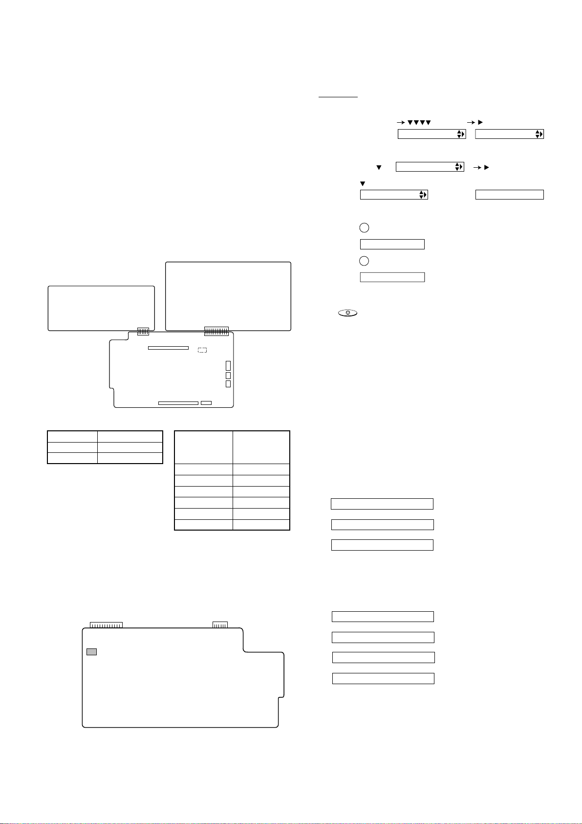
3. 2. ROM & RAM check
ROM executes the sum check, and RAM executes the matching test.
The result will be notified with the number of short sounds of the buzzer
as well as by printing the ROM & RAM check list.
Number of short sounds of buzzer 0 →No error
1 → ROM error
2 → RAM error (4 Kbyte SRAM or
512 Kbyte DRAM)
3. 3. Aging mode
If any document is present, copying will be executed sheet by sheet. If
no document is present,the checkpattern willbe printed sheetby sheet.
This operation will be executed at a rate of one sheet per 5 minutes, and
will be ended at a total of 10 sheets.
3. 4. Panel key test
This mode is used to check whether each key operates properly. Press
the key on the operation panel, and the key will be displayed on the
display. Therefore, press all keys. At this time, finally press the STOP
key.
When the STOP key is pressed, the keys which are not judged as
"pressed" will be printed on the result list.
•LED part of the contact image sensor (CIS) is kept on during the term
fromwhen "START"ofthe panel test mode to end withthe STOPkey.
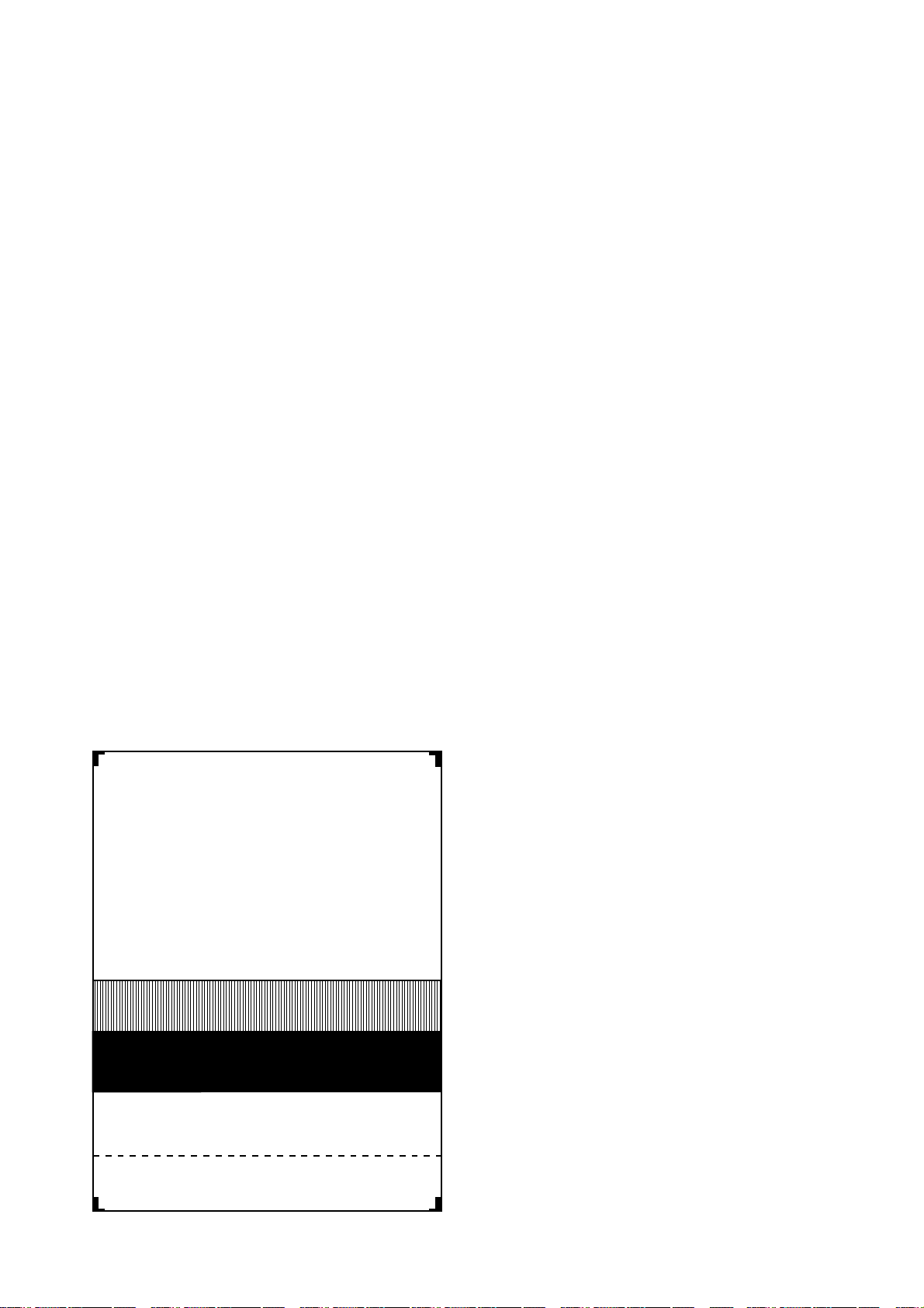
3. 5. Check pattern
This mode is used to check the state of the printing head. It is ended
with the following pattern printed on one printing sheet.
3. 6. Signal send mode
This mode is used to send various signals to the circuit during FAX com-
munication. Every push of START key sends a signal in the following
sequence.Moreover, the signal sound isalsooutput to the speaker when
the line monitor of the soft switch is on.
[1] No signals
[2] 14400BPS (V.33)
[3] 12000BPS (V.33)
[4] 14400BPS (V.17)
[5] 12000BPS (V.17)
[6] 9600BPS (V.17)
[7] 7200BPS (V.17)
[8] 9600BPS (V.29)
[9] 7200BPS (V.29)
[10] 4800BPS (V27ter)
[11] 2400BPS (V27ter)
[12] 300BPS (FLAG)
[13] 2100Hz (CED)
[14] 1100Hz (CNG)
3. 7. Memory clear
This mode is used to clear the backup memory and reset to the default
settings.
3. 8. Shading mode
The mode is used for the shading compensation. For reading, set up the
special original paper.
The compensation memorizes the reference data of white and black for
reading.
Moreover, the memorized data is not erased even if memory clear mode
is executed.
3. 9. All black print
This mode is used to check the state of the printing head and to inten-
tionally overheat it. Whole dots are printed over the interval of 2 m. If it is
overheatedor theprintingsheetis jammed,pressSTOP keyfor the end.
3. 10. Auto feeder mode
In this mode, a document is inserted and discharged to check the auto
feed function.
After this mode is started, set a document, and the document feed will
be automatically tested.
3. 11. Entry data send
This mode is used to send the registered data to another machine and
make the other machine copy the registered content.
Before sending in this mode, it is necessary to set the other machine at
the entry data receive mode.
The following, information will be sent to the remote machine:
1. Telephone list data
2. Sender register data
3. Optional setting content
4. Soft switch content
5. Junk fax number list
6. Recording setting list data
2 –3
1
B B B B B B B B B B B B B B B B B B B BB B B B B B B B B B B B B B B B B B B BB
2
3
4
1 DOT
2 DOTS
3 DOTS
4 DOTS

UX-A260U
3. 12. Entry data receive
In this mode, the registered data sent from the other machine is receiv-
ed and the received data is registered in the machine. When this mode
is used for receiving, the other machine must be in the entry data send
mode.
After receiving is completed, the following lists are printed.
1. Telephone list data
2. Sender register data (*)
3. Optional setting list (*)
4. Soft switch content
5. Junk fax number list (*)
6. Recording setting list data (*)
(*): Refer to SETUP LIST
2 –4
Press FUNCTION 9 8 7 STARTSTART
Press FUNCTION key.
Press key.
Press key.
Bit1 - 8 are set.
Soft SW-A2 - SW-O6 are set.
S F T SW-A1 = 1 0 0 0 0 0 0 0
S F T SW-A2 = 0 0 0 0 0 0 0 0
S F T SW-O6 = 0 0 0 0 0 0 0 0
Press key during setting.
To finish the settings halfway between
SW-A1 and SW-O6, press the STOP
key. In this case, the setting being done
to the SW No. on display will be nullified
while settings done to the preceding
SW No. remain in effect.
The soft switch mode is terminated.
S F T SW-A1 = 0 0 0 0 0 0 0 0
START
DATA No. 1 2 3 4 5 6 7 8
When the COPY key is pressed, the
contents of soft switches are printed.
4. How to make soft switch setting
To enter the soft switch mode, press the following key entries in se-
quence.
3. 13. Flash memory check
Data is written into and read from the flash memory to check data con-
formity. When the unit enters this mode, the check is started.
3. 14. Flash memory clear
Data in the flash memory is cleared (memory clear). When the unit en-
ters this mode, the check is started.
*Operation of hardware and signal in the flash memory check mode and
flash memory clear mode, and the result of check.
The result is announced by the buzzer beeps. The result of check is
printed.
Beeps
0 →No error
1 →Memory error
manuals4you.commanuals4you.com

UX-A260U
5. Soft switch description
•Soft switch
2 –5
1 Protect from echo No Yes 0
2 Forced 4800 BPS reception Yes No 0
3 Footer print Yes No 0
4 Length limitation of copy/send/receive No limit Copy/send: 60cm 0
Receive: 1m
5 CSI transmission No transmitted Transmitted 0
6 DIS receive acknowledgement during G3 Twice NSF: Once 0
transmission DIS: Twice
7 Non-modulated carrier for V29 transmission Yes No 0
mode
8 EOL detect timer 25 s 13 s 0
Modem speed V.33 V.17 V.29 V.27 ter
14400 12000 14400 12000 9600 7200 9600 7200 4800 2400
1 0011110000 1
2 1100000000 0
3 0101010110 0
4 0000111100 0
5 Sender’s information transmit No Yes 0
6 Reserved 0
7 Communication error treatment in RTN No communication error Communication error 0
sending mode (reception)
8 CNG transmission No Yes 0
CED tone signal interval 1000ms 750ms 500ms 75ms
1 No. 1 1 1 0 0 0
2 No. 2 1 0 1 0 0
3 MR coding No Yes 0
4 ECM mode No Yes 0 OPTION
5 ECM MMR mode No Yes 0
6 Reserved 0
7 Reserved 0
8 Reserved 0
1 Signal transmission level Binary input 0
2 No. = 16 8 4 2 1 1
3 1 2 3 4 5 0
4 0 1 0 0 0 0
5 0
6 Protocol monitor (error print) Printed at com. error Not printed 0
7 Protocol monitor Yes No 0
8 Line monitor Yes No 0
Digital line equalization setting (Reception) 7.2km 3.6km 1.8km 0km
1 No.1 11000
2 No.2 10101
Digital line equalization setting 7.2km 3.6km 1.8km 0km
3 (Transmission) No. 3 11000
4 No.4 10101
Digital cable equalizer setting (Reception 7.2km 0km
5 for Caller ID) No. 5 1 0 0
6 No. 6 1 0 0
7 Error criterion 10 ~ 20 % 5 ~ 10 % 0
8 Anti junk fax check Yes No 1
SW
NO. DATA
NO. ITEM Switch setting and function
10
Remarks
Initial
setting
SW
l
A1
SW
l
A2
SW
l
A3
SW
l
A5
SW
l
A4

UX-A260U
2 –6
1 Reserved 0
2 End Buzzer Yes No 1
3 Disconnect the line when DIS is received in No Yes 1
RX mode
4 Equalizer freeze control (MODEM) On Off 0
5 Equalizer freeze control 7200 BPS only No Yes 0
6 CNG transmission in manual TX mode Yes No 1
7 Reserved 0
8 Modem speed automatic fallback when RX Yes No 0
level is under -40dBm
1 Recall interval Binary input 0
2 No. = 8 4 2 1 1
3 1 2 3 4 0
4 0 1 0 1 1
5 Recall times Binary input 0
6 No. = 8 4 2 1 0
7 5 6 7 8 1
8 0 0 1 1 1
1 Dial pausing (sec/pause) 4 sec 2 sec 0
2 Dial tone detection (before auto dial) No Yes 1
3 Reserved 0
4 Busy tone detection (after auto dial) No Yes 0
Waiting time after dialing
45 seconds 55 seconds 90 seconds 140 seconds
5 No.5 00110
6 No.6 01010
7 Reserved 0
8 Reserved 0
1 Reserved 0
2 Reserved 0
3 Reserved 0
4 Reserved 0
5 Reserved 0
Auto dial mode delay timer of before line
0 second 1.5 seconds 3.0 seconds 4.5 seconds
6 connect No.6 00110
7 No.7 01010
8 Hold key Enable Disable 1
Auto dial mode delay timer of after line
1.7 seconds 3.0 seconds 3.6 seconds 4.0 seconds
1 connect No.1 00110
2 No.2 01010
3 Dial mode Tone Pulse 1 OPTION
4 Pulse →Tone change function by key Enable Disable 1
5 Dial pulse make/break ratio (%) 40/60 33/67 1
6 Reserved 0
7 Reserved 0
8
Recalling fixed only one time when dialing was
Yes No 1
unsuccessful without detecting busy tone signal
1 DTMF signal transmission level (Low) Binary input 0
2 No. = 16 8 4 2 1 1
3 1 2 3 4 5 0
4 0 1 0 0 1 0
5 1
6 Reserved 0
7 Reserved 0
8 Reserved 0
SW
NO. DATA
NO. ITEM Switch setting and function
10
Remarks
Initial
setting
SW
l
B5
SW
l
B4
SW
l
B3
SW
l
B2
SW
l
B1
SW
l
A6
manuals4you.commanuals4you.com

UX-A260U
2 –7
1 DTMF signal transmission level (High) Binary input 0
2 No. = 16 8 4 2 1 0
3 1 2 3 4 5 1
4 0 0 1 0 1 0
5 1
6 0
7 Reserved 0
8 Reserved 0
Reading slice (Binary) Factory Light Dark Darker in
setting dark
1 No.1 0 1 0 1 0
2 No. 2 0 0 1 1 0
Reading slice (Half tone) Factory Light Dark Darker in
setting dark
3 No.3 0 1 0 1 0
4 No.4 0 0 1 1 0
5 Line density selection Fine Standard 0
6 Reserved 0
7 MTF correction in half tone mode No Yes 0
8 Reserved 0
1 Number of rings for auto receive Binary input 0 OPTION
2 No. = 8 4 2 1 1
3 1 2 3 4 0
4 0 1 0 0 0
5 Automatic switching manual to auto receive Reception after 5 rings No reception 0
mode
6 Reserved 0
Cl detect frequency
As PTT 11.5Hz 13.0Hz 20.0Hz
7 No.7 0 0 1 1 0
8 No.8 0 1 0 1 0
Distinctive ringing setting No.1 No.2 No.3 OPTION
(PATTERN 4 and 5 are for CANADA only) OFF 0 0 0
STANDARD 0 0 1
PATTERN1 0 1 0
PATTERN2 0 1 1
1 PATTERN3 1 0 0 0
2 PATTERN4 1 0 1 0
3 PATTERN5 1 1 0 0
4 Reserved 0
5 Caller ID function Yes No 0 OPTION
6 Caller ID detect during CI off All times Only first 0
7 Reserved 0
8 Reserved 0
1 Cl off detection timer (0-1550ms setting by Binary input 0
2 50ms step) No.= 16 8 4 2 1 1
3 1 2 3 4 5 1
4 0 1 1 1 0 1
5 0
6 Reserved 0
7 Reserved 0
8 Reserved 0
SW
NO. DATA
NO. ITEM Switch setting and function
10
Remarks
Initial
setting
SW
l
B6
SW
l
C1
SW
l
D2
SW
l
D1
SW
l
D3

UX-A260U
1 Reserved 0
2 Reserved 0
3 Reserved 0
4 Reserved 0
5 Reserved 0
6 Reserved 0
7 Reserved 0
8 Reserved 0
1 Reserved 0
2 Reserved 0
3 Reserved 0
4 Reserved 0
5 Reserved 0
6 Reserved 0
7 Reserved 0
8 Reserved 0
1 Reserved 0
2 Reserved 0
3 Reserved 0
4 Reserved 0
5 Reserved 0
6 Reserved 0
7 Reserved 0
8 Reserved 0
DTMF detection time 50ms 80ms 100ms 120ms
1 No.1 0 0 1 1 0
2 No. 2 0 1 0 1 0
3 Protection of remote reception (5 ) detect Yes No 1
4 Remote reception with GE telephone Compatible Not compatible 1
5 Remote operation code figure by external Binary input 0
6 TEL (0~9) No. = 8 4 2 1 1
7 5 6 7 8 0
8 0 1 0 1 1
1 CNG detection in STAND-BY mode Yes No 1 OPTION
Number of CNG detect (AM mode) 1pulse 2pulses 3pulses 4pulses
2 No.2 0 0 1 1 0
3 No. 3 0 1 0 1 1
Number of CNG detect (STAND-BY mode) 1pulse 2pulses 3pulses 4pulses
4 No.4 0 0 1 1 0
5 No. 5 0 1 0 1 1
6 Reserved 0
7 Reserved 0
8 Reserved 0
1 Reserved 0
2 Reserved 0
3 Reserved 0
4 Reserved 0
5 Reserved 0
6 Reserved 0
7 Reserved 0
8 Reserved 0
2 –8
SW
l
E1
SW
NO. DATA
NO. ITEM Switch setting and function
10Remarks
Initial
setting
SW
l
E2
SW
l
E3
SW
l
F1
SW
l
F2
SW
l
G1
manuals4you.commanuals4you.com

UX-A260U
2 –9
1 Reserved 0
2 Reserved 0
3 Reserved 0
4 Reserved 0
5 Reserved 0
6 Reserved 0
7 Reserved 0
8 Reserved 0
1 Reserved 0
2 Reserved 0
3 Reserved 0
4 Reserved 0
5 Reserved 0
6 Reserved 0
7 Reserved 0
8 Reserved 0
Busy tone detection ON/OFF time (Lower 150ms 200ms 250ms 350ms
1 duration) No. 1 0 0 1 1 0
2 No.2 0 1 0 1 1
Busy tone detection ON/OFF time (Upper 650ms 900ms 1500ms 2700ms
3 duration) No.3 0 0 1 1 0
4 No.4 0 1 0 1 1
5 Busy tone detect continuation sound detect No Yes 0
during OGM
6 Busy tone detect continuation sound detect No Yes 0
7 Busy tone detect intermittent sound detect No Yes 0
during OGM
8 Busy tone detect intermittent sound detect No Yes 0
Busy tone detection pulse number 2pulses 4pulses 6pulses 10pulses
1 No. 1 0 0 1 1 0
2 No. 2 0 1 0 1 1
3 Fax switching when A.M. full Yes No 0 OPTION
4 Busy tone detect continuation sound detect 320Hz - 570Hz 320Hz - 460Hz 0
frequency
5 Reserved 0
6 Reserved 0
7 AM OGM announce only mode Yes No 0 OPTION
8 Busy tone continuous sound detect time 5s 10s 1
ICM recording time 4min 15s 30s 60s OPTION
1 No. 1 0 0 1 1 0
2 No. 2 0 1 0 1 0
A.M. quiet time 1 2s 3s 4s 5s
3 No. 3 0 0 1 1 0
4 No. 4 0 1 0 1 0
A.M. quiet time 2 0s 1s 2s 3s
5 No. 5 0 0 1 1 1
6 No. 6 0 1 0 1 0
7 Key input buzzer on/off switch (Two way On Off 0
recording mode)
8 CPC signal detection Yes No 1 OPTION
SW
l
G2
SW
NO. DATA
NO. ITEM Switch setting and function
10Remarks
Initial
setting
SW
l
G3
SW
l
H1
SW
l
H2
SW
l
I1

UX-A260U
1 A.M. quiet detect time Binary input 0
2 No. = 16 8 4 2 1 0
3 1 2 3 4 5 1
4 00110 1
5 0
CPC detection time
4ms 20ms 40ms 70ms 140ms 160ms 200ms 290ms
6 No.6 0 0 0 0 1111 1
7 No.7 0 0 1 1 0011 1
8 No.8 0 1 0 1 0101 1
1 Reserved 0
2 Max OGM record time 15s 60s 0
3 Two way record function Disable Enable 0
4 Toll saver Disable Enable 0 OPTION
5 Reserved 0
6 Reserved 0
7 Reserved 0
8 Transfer dial recall No Yes 0
1 AGC maximum gain (line) Binary input 0
2 (10 ~ 25 dB) (1 dB step) No. = 8 4 2 1 1
3 1 2 3 4 0
4 0101 1
5 AGC maximum gain (Mic) Binary input 0
6 (10 ~ 25 dB) (1 dB step) No. = 8 4 2 1 1
7 5 6 7 8 1
8 0110 0
1
AGC energy refrence level access code (line)
Binary input 1
2 (-0 ~ -30 dB) (2 dB step) No. = 8 4 2 1 0
3 1 2 3 4 1
4 1011 1
5
AGC energy refrence level access code (Mic)
Binary input 1
6 (-0 ~ -30 dB) (2 dB step) No. = 8 4 2 1 1
7 5 6 7 8 0
8 1101 1
1 AGC again adaptation threshold (line) Binary input 1
2 No. = 8 4 2 1 1
3 1 2 3 4 1
4 1111 1
5 AGC again adaptation threshold (Mic) Binary input 1
6 No. = 8 4 2 1 1
7 5 6 7 8 1
8 1111 1
AGC slew rate (line) Slow Normal Little fast Fast
1 No. 1 0 0 1 1 0
2 No. 2 0 1 0 1 1
AGC slew rate (Mic) Slow Normal Little fast Fast
3 No. 3 0 0 1 1 1
4 No. 4 0 1 0 1 1
5 Reserved 0
6 Reserved 0
7 Reserved 0
8 Reserved 0
2 –10
SW
l
I3
SW
l
I4
SW
l
I5
SW
l
I6
SW
NO. DATA
NO. ITEM Switch setting and function
10Remarks
Initial
setting
SW
l
I7
SW
l
I2
manuals4you.commanuals4you.com

UX-A260U
2 –11
1 Reserved 0
2 Reserved 0
3 Sender’s phone number setting Cannot change Change allowed 0
4 Reserved 0
5 Reserved 0
6 Summer time setting No Yes 1 OPTION
Ringer volume Off Low Middle High OPTION
7 No. 7 0 0 1 1 1
8 No. 8 0 1 0 1 0
1 Reserved 0
2 Reserved 0
3 Reserved 0
Handset receiver volume Low Low Middle High OPTION
4 No. 4 0 0 1 1 1
5 No. 5 0 1 0 1 0
Speaker volume (5 stages)
Very Low
Low Middle High
Very High
OPTION
6 No. 6 000010
7 No. 7 001101
8 No. 8 010100
1 Reserved 0
Communication results printout E/T/M
Send only
Always No print Err only OPTION
2(Transaction report) No. 2 000011
3 No. 3 001100
4 No. 4 010100
5 OGM/ICM output level to speaker Binary input 0
6 (0 dB ~ -15 dB) (1 dB step) No. = 8 4 2 1 0
7 5 6 7 8 1
800111
1 Reserved 0
2 Reserved 0
3 OGM/ICM output level Binary input 0
4 (0 dB ~ -32 dB) (1 dB step) No. = 32 16 8 4 2 1 0
5 3 45678 1
6 0 01001 0
7 0
8 1
1 Reserved 0
2 Reserved 0
3 Reserved 0
4 Reserved 0
5 Cut off mode (COPY mode) Yes No 1 OPTION
6 A4 paper enable Enable Disable 0
7 LEGAL & LETTER paper enable Enable Disable 1
8 Reserved 0
SW
l
J2
SW
l
J3
SW
l
K1
SW
l
L1
SW
NO. DATA
NO. ITEM Switch setting and function
10Remarks
Initial
setting
SW
l
J1

UX-A260U
2 –12
Paper set size LETTER LEGAL A4 OPTION
1 No. 1 0 0 1 0
2 No. 2 0 1 0 0
3 Automatic reduce of receive Auto 100 % 1 OPTION
Print contrast Normal Lighter Light Dark Darker OPTION
4 No. 4 000011
5 No. 5 001100
6 No. 6 010100
7
Reception reduction ratio in case of memory ful
100 % 93 % 0
8 Reserved 0
1 Reserved 0
2 Reserved 0
3 Reserved 0
4 Reserved 0
5 Reserved 0
6 Reserved 0
7 Reserved 0
8 Reserved 0
1 Reserved 0
2 Reserved 0
3 Reserved 0
4 Reserved 0
5 Reserved 0
6 Reserved 0
7 Reserved 0
8 Reserved 0
1 Reserved 0
2 Reserved 0
3 Reserved 0
4 Reserved 0
5 Reserved 0
6 Reserved 0
7 Reserved 0
8 Reserved 0
1 Reserved 0
2 Reserved 0
3 Reserved 0
4 Reserved 0
5 Reserved 0
6 Reserved 0
7 Reserved 0
8 Reserved 0
1 Reserved 0
2 Reserved 0
3 Reserved 0
4 Reserved 0
5 Reserved 0
6 Reserved 0
7 Reserved 0
8 Reserved 0
SW
l
M2
SW
l
N1
SW
NO. DATA
NO. ITEM Switch setting and function
10Remarks
Initial
setting
SW
l
N2
SW
l
N3
SW
l
M1
SW
l
L2
manuals4you.commanuals4you.com

UX-A260U
2 –13
1 Reserved 0
2 Reserved 0
3 Reserved 0
4 Reserved 0
5 Reserved 0
6 Reserved 0
7 Reserved 0
8 Reserved 0
1 Reserved 0
2 Reserved 0
3 Reserved 0
4 Reserved 0
5 Reserved 0
6 Reserved 0
7 Reserved 0
8 Reserved 0
1 Reserved 0
2 Reserved 0
3 Reserved 0
4 Reserved 0
5 Reserved 0
6 Reserved 0
7 Reserved 0
8 Reserved 0
1 Reserved 0
2 Reserved 0
3 Reserved 0
4 Reserved 0
5 Reserved 0
6 Reserved 0
7 Reserved 0
8 Reserved 0
1 Reserved 0
2 Reserved 0
3 Reserved 0
4 Reserved 0
5 Reserved 0
6 Reserved 0
7 Reserved 0
8 Reserved 0
1 Reserved 0
2 Reserved 0
3 Reserved 0
4 Reserved 0
5 Reserved 0
6 Reserved 0
7 Reserved 0
8 Reserved 0
SW
l
O3
SW
l
O4
SW
NO. DATA
NO. ITEM Switch setting and function
10
Remarks
Initial
setting
SW
l
O5
SW
l
O6
SW
l
O2
SW
l
O1

UX-A260U
TX RX
CED
DIS
T
2 –14
•Soft switch function description
SW-A1 No. 1 Protect from echo
Used to protect from echo in reception.
SW-A1 No. 2 Forced 4800BPS reception
When line conditions warrant that receptions take place at 4800 BPS
repeatedly.
It may improve the success of receptions by setting at 4800BPS.
This improves the receiving document quality and reduces handshake
time due to fallback during training.
SW-A1 No. 3 Footer print
When set to "1", the date of reception, the sender machine No., and the
page No. are automatically recorded at the end of reception.
SW-A1 No. 4 Length limitation of copy/send/receive
Used to set the maximum page length.
To avoid possible paper jam, the page length is normally limited to 0.6
meter for copy or transmit, and 1 meters for receive.
It is possible to set it to "No limit" to transmit a long document, such as a
computer print form, etc. (In this case, the receiver must also be set to
no limit.)
SW-A1 No. 5 CSI transmission
(CSITRANSMISSION) is a switch to set whether the machine sends or
does not send the signal (CSI signal) informing its own telephone No. to
theremotefaxmachinewheninformationisreceived.When "nonsending"
is set, the telephone No. is not output on the remote transmitting ma-
chine if the remote transmitting machine has the function to display or
print the telephone No. of receiving machine, using this CSI signal.
SW-A1 No. 6 DIS receive acknowledgment during G3 transmission
Used to make a choice of whether reception of DIS (NSF) is acknowl-
edgedafter receiving two DISs(NSFs) or receiving one DIS (two NSFs).
It may be useful for overseas communication to avoid an echo sup-
pression problem, if set to 1.
SW-A1 No. 7 Non-modulated carrier for V29 transmission mode
Thoughtransmissionof a non-modulated carrier isnotrequiredfor trans-
mission by the V29 modem according to the CCITTrecommendation, it
may be permitted to a send non-modulated carrier before the image
signal to avoid an echo suppression problem. It may be useful for over-
seas communication to avoid an echo suppression problem, if set to 1.
SW-A1 No. 8 EOL (End Of Line) detect timer
Used to make a choice of whether to use the 25-second or 13-second
timer for detection of EOL.
This is effective to override communication failures with some facsimile
models that have longer EOL detection.
SW-A2 No. 1 ~ No. 4 Modem speed
Used to set the initial modem speed. The default is 14400BPS.
It may be necessary to program it to a slower speed when frequent line
fallback is encountered, in order to save the time required for fallback
procedure.
SW-A2 No. 5 Sender’s information transmit
(SENDER’S INFORMATION TRANSMISSION) is a switch to set the
functiontoprintthecontentofHEADERPRINTdescribedinthepasscode
list at the front end of receiver’s original when original is sent to the
remote machine.
If this switch is set to "NO", the HEADER PRINT is not output at the
receiving machine.
SW-A2 No. 6 Reserved
Set to "0".
SW-A2 No. 7 Communication error treatment in RTN sending mode
(Reception)
Used to determine communication error treatment when RTN is sent by
occurrence of a received image error in G3 reception. When it is set to
"1", communication error is judged as no error.
SW-A2 No. 8 CNG transmission
When set to "0" , this model allows CNG transmission by pressing the
Start key in the key pad dialing mode. When set to "1", CNG transmis-
sion in the key pad dialing mode cannot be performed. In either case.
CNG transmission can be performed in the auto dial mode.
SW-A3 No. 1, No. 2 CED tone signal interval
For international communication, the 2100Hz CED tone may act as an
echo suppression switch, causing a communication problem.
ThoughSW-A3No.1 and No. 2 are normally setto 0, this setting is used
to change the time between the CED tone signal to eliminate the com-
munication caused by echo.
SW-A3 No. 3 MR Coding
MR Coding is enable.
SW-A3 No. 4 ECM mode
Used to determine ECM mode function. Refer to following table.
(Depending on remote machine)
SW-A3 No. 5 ECM MMR mode
See SW-A3 No. 4.
SW-A3 No. 6 ~ No. 8 Reserved
Set to "0".
SW-A4 No. 1 ~ No. 5 Signal transmission level
Used to control the signal transmission level in the range of-0dB to-
31dB.
SW-A4 No. 6 Protocol monitor (Error print)
If set to "1", protocol is printed at communication error.
SW-A4 No. 7 Protocol monitor
Normally set to "0". If set to "1", communication can be checked, in case
of trouble, without using a G3 tester or other tools.
When communication FSK data transmission or reception is made, the
data is taken into the buffer. When communication is finished, the data
is analyzed and printed out. When data is received with the line monitor
(SW-A4 No. 8) set to "1" the reception level is also printed out.
SW-A4 No. 8 Line monitor
Normally set to "0". If set to "1", the transmission speed and the recep-
tion level are displayed on the LCD. Used for line tests.
SW-A5 No. 1, No. 2 Digital line equalization setting (Reception)
Line equalization when reception is to be set according to the line char-
acteristics.
Setting should be made according to distance between the telephone
and the telephone company central switching station.
SW-A5 No. 3, No. 4 Digital line equalization setting (Transmission)
Line equalization when transmitter is to be set according to the line
characteristics.
Setting should be made according to distance between the telephone
and the telephone company central switching station.
SW-A3 No.4 ECM MODE 0 0 1 1
SW-A3 No.5 ECM MMR MODE 0 1 0 1
Compression ECM MMR mode Yes No No No
method ECM MH mode Yes Yes No No
MR Mode Yes Yes Yes Yes
manuals4you.commanuals4you.com
This manual suits for next models
1
Table of contents
Other Sharp Fax Machine manuals

Sharp
Sharp AR-F151 User manual

Sharp
Sharp UX-108 User manual

Sharp
Sharp UX-E800 User manual

Sharp
Sharp UX-P410 User manual

Sharp
Sharp XUX-510 User manual

Sharp
Sharp UX-51 User manual

Sharp
Sharp FO-IS110N User manual

Sharp
Sharp FO-4450 User manual

Sharp
Sharp FO-2970M User manual

Sharp
Sharp FO-3150 User manual