1 – 4
FO-2950MGR/GH/MY/TH
[4] Installation
1. Site selection
Take the followingpoints into considerationwhen selecting asite for this
model.
ENVIRONMENT
•The machine must be installed on a level surface.
•Keep the machine away from air conditioners, heaters, direct sun-
light, and dust.
•Provide easy access to the front, back, and sides of the machine. In
particular, keep the area in front of the machine clear, or the original
document may jam as it comes out after scanning.
•The temperature should be between 10°and 30°C (50°and 86°F).
•The humidity should be between 20% and 85% (without condensa-
tion).
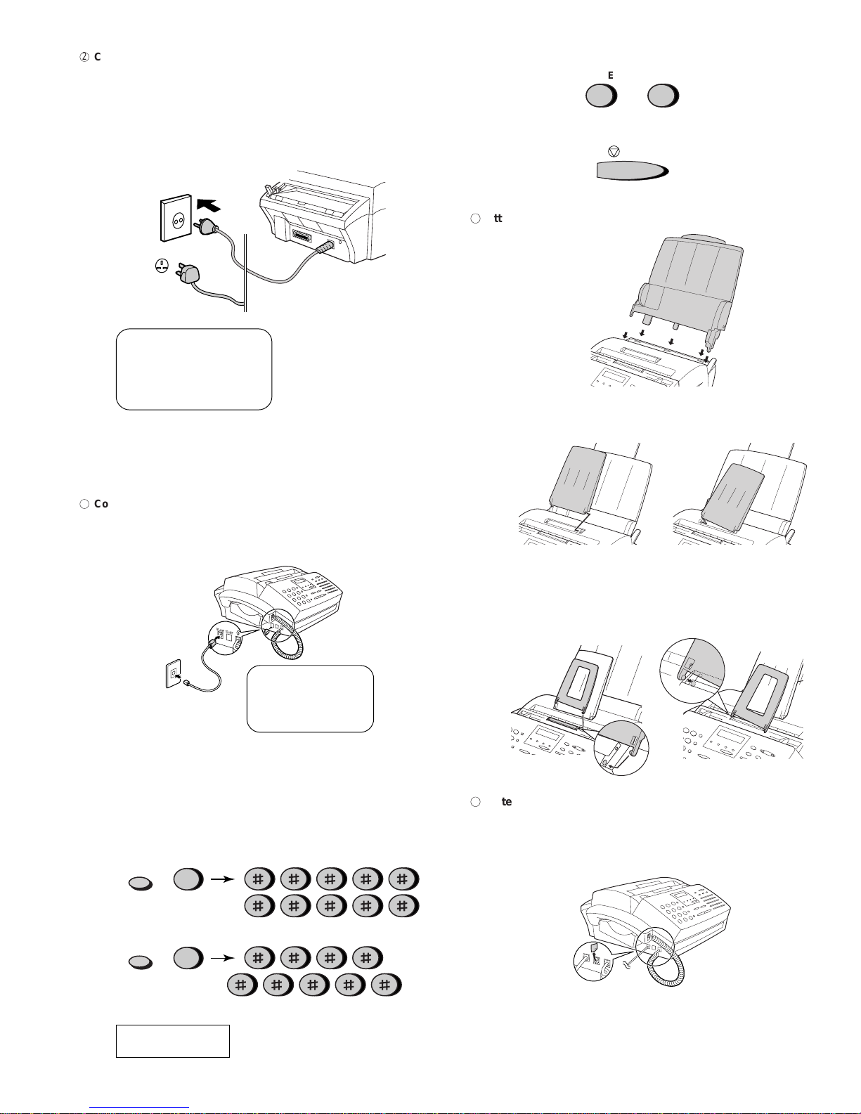
ELECTRICITY
FO-2950MGR/GH/TH
AC 220-240 V, 50/60 Hz, earthed (2-prong) AC outlet is required.
FO-2950MMY
AC 220-240 V, 50/60 Hz, earthed (3-prong) AC outlet is required.
Caution!
•Connection to a power source other than that specified will cause
damage to the equipment and is not covered under the warranty.
•Ifyourareaexperiencesa high incidence of lightning or power surges,
we recommend that you install a surge protector for the power and
telephonelines.Surgeprotectorscanbepurchasedatmosttelephone
speciality stores
TELEPHONE SOCKET
Astandard telephone socket must be located near the machine. This is
the telephone socket commonly used in most homes and offices.
•Plugging the fax machine into a socket which is not a socket may
result in damage to the machine or your telephone system. If you do
not know what kind of socket you have, or need to have one in-
stalled, contact the telephone company.
If the machine is moved from a cold to a warm place...
If the machine is moved from a cold to a warm place, it is possible that
thereading glass mayfog up, preventingproper scanning ofdocuments
for transmission. To remove the fog, turn on the power and wait approxi
mately 2 hours before using the machine.
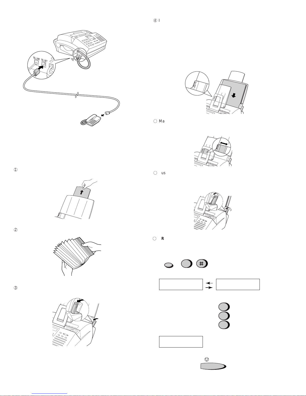
The laser printer in your fax machine uses a toner cartridge and a
drum cartridge. The drum cartridge comes pre-installed, and the
toner cartridge must be installed.
• The drum cartridge can print approximately 20,000 A4-size
pages. When replacing the drum cartridge, use a Sharp
FO-29DR drum cartridge.
Follow the steps below to install the toner cartridge and prepare the
drum cartridge.
1
Grasp the print compartment cover at both sides as shown, and
pull up to open the cover.
•Caution! The fusing unit inside the print compartment becomes
very hot during operation. Do not touch the inside of the
compartment or the paper guide on the underside of the print
compartment cover.
2
The drum cartridge has been installed at the factory. Gently pull
the paper tab to remove the black sheet of protective paper from
the cartridge.
• Be careful not to tear the paper nor leave any pieces of paper in
the machine.
The starter toner cartridge
included with your fax can
print approximately 1,875
A4-size pages at 4% page
coverage.
When replacing the toner
cartridge, use a Sharp
FO-29DC toner cartridge.
One cartridge can print about
3,750 A4-size pages.
2. Installing the toner cartridges