Sharp FO-DC600 User manual

1 - 1
FO-DC600U
No. 00ZFDC600USME
Parts marked with " " is important for maintaining the safety of the set. Be sure to replace these parts with specified ones for
maintaining the safety and performance of the set.
This document has been published to be used
for after sales service only.
The contents are subject to change without notice.
SHARP CORPORATION
SERVICE MANUAL
Laser Wave Length : 770-795 nm
Laser Pulse Times : 51.3 ns
Laser Output Power : 5 mW
CAUTION
This laser printer is a class 1 laser product that complies with 21CFR 1040.10 and 1040.11 of the CDRH or IEC60825-1 standard. This
means that this machine does not produce a hazardous laser radiation. The use of controls, adjustments or performance of procedures
other than those specified herein may result in hazardous radiation exposure.
This laser radiation is not a danger to the skin, but when an exact focusing of the laser beam is achieved on the eyes retina, there is
danger of spot damage to the retina.
The following cautions must be observed to avoid exposure of the laser beam to your eyes at the time of servicing.
1) When a problem in the laser optical unit has occurred, the whole optical unit must be exchanged as a unit.
2) Do not look into the machine with the Main Switch turned on after removing the Toner/Developer unit and Drum Cartridge.
3) Do not look into the laser beam exposure slit of the Laser Optical Unit with the connector connected when removing and installing
the Optical Unit.
4) The cover of Laser Printer Unit contains the Safety Interlock Switch.
Do not defeat the safety interlock by inserting wedges or other items into the switch slot.
MODEL SELECTION CODE DESTINATION
FO-DC600 U U.S.A./Canada
OPTION
Toner cartridge: FO-50ND
Drum cartridge: FO-47DR
Option memory: FO-8MK
Verification stamp: FO-45VS
Paper cassette: FO-CS1
LAN Network interface kit: FO-LN1
Network printer kit: FO-NP1
Network scanner kit: FO-NS2
Dual line kit: FO-60DL
NOTE:
• FO-NP1 (Network Printer Kit) and FO-60DL (Dual Line Kit) can not
be mounted simultaneously.
• FO-LN1 (LAN Network Interface Kit) and FO-60DL (Dual Line Kit)
can be mounted simultaneously. However, multi-operation of
2 line communication and network scan is not possible.
FACSIMILE
FO-DC600
MODEL
Chapters 1, 2, 3, 7 and 8 of this manual are omitted because they are partly common to the FO-4400U/
FO-DC500U. Please refer to previous service manual (00ZFO4400USME) / (00ZFODC500SME) for these
chapters.

1 –2
FO-DC600U CONTENTS
• CAUTION FOR BATTERY REPLACEMENT
• PRECAUTIONS FOR USING LEAD-FREE SOLDER
CHAPTER 1. GENERAL DESCRIPTION
[1] Specifications . . . . . . . . . . . . . . . . . . . . . . . . . . . . . . . . . . . . . . . . . . . . . . . . . . . . . . . . . . . . . . . . . . 1-1
[2] Life of consumable . . . . . . . . . . . . . . . . . . . . . . . . . . . . . . . . . . . . . . . . . . . . . . . . . . . . . . . . . . . . . . 1-1
[3] Operation panel . . . . . . . . . . . . . . . . . . . . . . . . . . . . . . . . . . . . . . . . . . . . . . . . . . . . . . . . . . . . . . . . 1-2
[4] Refer to the service manual of FO-DC500U.
[5] Refer to the service manual of FO-DC500U.
[6] Refer to the service manual of FO-DC500U.
[7] Installing the Dual Line Kit (FO-60DL) . . . . . . . . . . . . . . . . . . . . . . . . . . . . . . . . . . . . . . . . . . . . . . . 1-4
[8] Installing the Third Paper Cassette (FO-CS1) . . . . . . . . . . . . . . . . . . . . . . . . . . . . . . . . . . . . . . . . . 1-5
CHAPTER 2. ADJUSTMENTS
[1] Adjustments . . . . . . . . . . . . . . . . . . . . . . . . . . . . . . . . . . . . . . . . . . . . . . . . . . . . . . . . . . . . . . . . . . . 2-1
[2] Diagnostics and service soft switches . . . . . . . . . . . . . . . . . . . . . . . . . . . . . . . . . . . . . . . . . . . . . . . 2-2
[3] Refer to the service manual of FO-4400U.
[4] Refer to the service manual of FO-4400U.
[5] Refer to the service manual of FO-4400U.
[6] Refer to the service manual of FO-4400U.
CHAPTER 3. MECHANICAL DESCRIPTION
[1] Refer to the service manual of FO-DC500U.
[2] Refer to the service manual of FO-DC500U.
[3] Disassembly and assembly procedures . . . . . . . . . . . . . . . . . . . . . . . . . . . . . . . . . . . . . . . . . . . . . . 3-1
[4] Refer to the service manual of FO-4400U.
CHAPTER 4. DIAGRAMS
[1] Block diagram . . . . . . . . . . . . . . . . . . . . . . . . . . . . . . . . . . . . . . . . . . . . . . . . . . . . . . . . . . . . . . . . . 4-1
[2] Wiring diagram . . . . . . . . . . . . . . . . . . . . . . . . . . . . . . . . . . . . . . . . . . . . . . . . . . . . . . . . . . . . . . . . . 4-2
[3] Point-to-point diagram and connector signal name . . . . . . . . . . . . . . . . . . . . . . . . . . . . . . . . . . . . . 4-3
CHAPTER 5. CIRCUIT DESCRIPTION
[1] Circuit description . . . . . . . . . . . . . . . . . . . . . . . . . . . . . . . . . . . . . . . . . . . . . . . . . . . . . . . . . . . . . . . 5-1
[2] Circuit description of control PWB . . . . . . . . . . . . . . . . . . . . . . . . . . . . . . . . . . . . . . . . . . . . . . . . . . 5-1
[3] Circuit description of CIS unit . . . . . . . . . . . . . . . . . . . . . . . . . . . . . . . . . . . . . . . . . . . . . . . . . . . . . 5-15
[4] Circuit description of LIU PWB . . . . . . . . . . . . . . . . . . . . . . . . . . . . . . . . . . . . . . . . . . . . . . . . . . . . 5-16
[5] Circuit description of operation panel PWB . . . . . . . . . . . . . . . . . . . . . . . . . . . . . . . . . . . . . . . . . . 5-18
[6] Circuit description of power supply PWB . . . . . . . . . . . . . . . . . . . . . . . . . . . . . . . . . . . . . . . . . . . . 5-19
[7] Circuit description of Dual Line Kit (FO-60DL) . . . . . . . . . . . . . . . . . . . . . . . . . . . . . . . . . . . . . . . . 5-20
CHAPTER 6. CIRCUIT SCHEMATICS AND PARTS LAYOUT
[1] Control PWB circuit . . . . . . . . . . . . . . . . . . . . . . . . . . . . . . . . . . . . . . . . . . . . . . . . . . . . . . . . . . . . . 6-1
[2] LIU PWB circuit . . . . . . . . . . . . . . . . . . . . . . . . . . . . . . . . . . . . . . . . . . . . . . . . . . . . . . . . . . . . . . . 6-18
[3] Printer PWB circuit . . . . . . . . . . . . . . . . . . . . . . . . . . . . . . . . . . . . . . . . . . . . . . . . . . . . . . . . . . . . . 6-21
[4] Power supply PWB circuit . . . . . . . . . . . . . . . . . . . . . . . . . . . . . . . . . . . . . . . . . . . . . . . . . . . . . . . 6-25
[5] Operation panel PWB circuit . . . . . . . . . . . . . . . . . . . . . . . . . . . . . . . . . . . . . . . . . . . . . . . . . . . . . 6-27
[6] LCD Relay PWB circuit . . . . . . . . . . . . . . . . . . . . . . . . . . . . . . . . . . . . . . . . . . . . . . . . . . . . . . . . . 6-31
CHAPTER 7. OPERATION FLOWCHART
[1] Refer to the service manual of FO-4400U.
[2] Refer to the service manual of FO-4400U.
[3] Refer to the service manual of FO-4400U.
CHAPTER 8. OTHERS
[1] Service Tools . . . . . . . . . . . . . . . . . . . . . . . . . . . . . . . . . . . . . . . . . . . . . . . . . . . . . . . . . . . . . . . . . . 8-1
[2] Refer to the service manual of FO-4400U.
PARTS GUIDE

1 - 3
FO-DC600U
(Danish) ADVARSEL !
Lithiumbatteri-Eksplosionsfare ved fejlagtig håndtering.
Udskiftning må kun ske med batteri af samme fabrikat og type.
Levér det brugte batteri tilbage til leverandoren.
(English) Caution !
Danger of explosion if battery is incorrectly replaced.
Replace only with the same or equivalent type
recommended by the equipment manufacturer.
Discard used batteries according to manufacturer’s instructions.
(Finnish) VAROITUS
Paristo voi räjähtää, jos se on virheellisesti asennettu.
Vaihda paristo ainoastaan laitevalmistajan suosittelemaan
tyyppiin. Hävitä käytetty paristo valmistajan ohjeiden mukaisesti.
(French) ATTENTION
Il y a danger d’explosion s’ il y a remplacement incorrect
de la batterie. Remplacer uniquement avec une batterie du
même type ou d’un type recommandé par le constructeur.
Mettre au rébut les batteries usagées conformément aux
instructions du fabricant.
(Swedish) VARNING
Explosionsfare vid felaktigt batteribyte.
Använd samma batterityp eller en ekvivalent
typ som rekommenderas av apparattillverkaren.
Kassera använt batteri enligt fabrikantens
instruktion.
(German) Achtung
Explosionsgefahr bei Verwendung inkorrekter Batterien.
Als Ersatzbatterien dürfen nur Batterien vom gleichen Typ oder
vom Hersteller empfohlene Batterien verwendet werden.
Entsorgung der gebrauchten Batterien nur nach den vom
Hersteller angegebenenAnweisungen.
11
11
1
Employing lead-free solder
The Power supply PWB of this model employs lead-free solder. This is indicated by the “LF” symbol printed on the PWB
and in the service manual.
The suffix letter indicates the alloy type of the solder.
Example:
Indicates lead-free solder of tin, silver and copper.
22
22
2
Using lead-free solder
When repairing a PWB with the “LF” symbol, only lead-free solder should be used. (Using normal tin/lead alloy solder may
result in cold soldered joints and damage to printed patterns.)
As the melting point of lead-free solder is approximately 40ºC higher than tin/lead alloy solder, it is recommended that a
dedicated bit is used, and that the iron temperature is adjusted accordingly.
33
33
3
Soldering
As the melting point of lead-free solder (Sn-Ag-Cu) is higher and has poorer wettability (flow), to prevent damage to the land
of the PWB, extreme care should be taken not to leave the bit in contact with the PWB for an extended period of time.
Remove the bit as soon as a good flow is achieved.
The high content of tin in lead free solder will cause premature corrosion of the bit.
To reduce wear on the bit, reduce the temperature or turn off the iron when it is not required.
Leaving different types of solder on the bit will cause contamination of the different alloys, which will alter their
characteristics, making good soldering more difficult.
It will be necessary to clean and replace bits more often when using lead-free solder. To reduce bit wear, care should be
taken to clean the bit thoroughly after each use.
CAUTION FOR BATTERY REPLACEMENT
PRECAUTIONS FOR USING LEAD-FREE SOLDER

FO-DC600U
<IMPORTANT PLEASE READ FIRST>
To avoid problems with supplies, please don’t use supplies from other units. Please use new supplies, when supply changes are required.
CHAPTER 1. GENERAL DESCRIPTION
[1] Specifications
• GENERAL
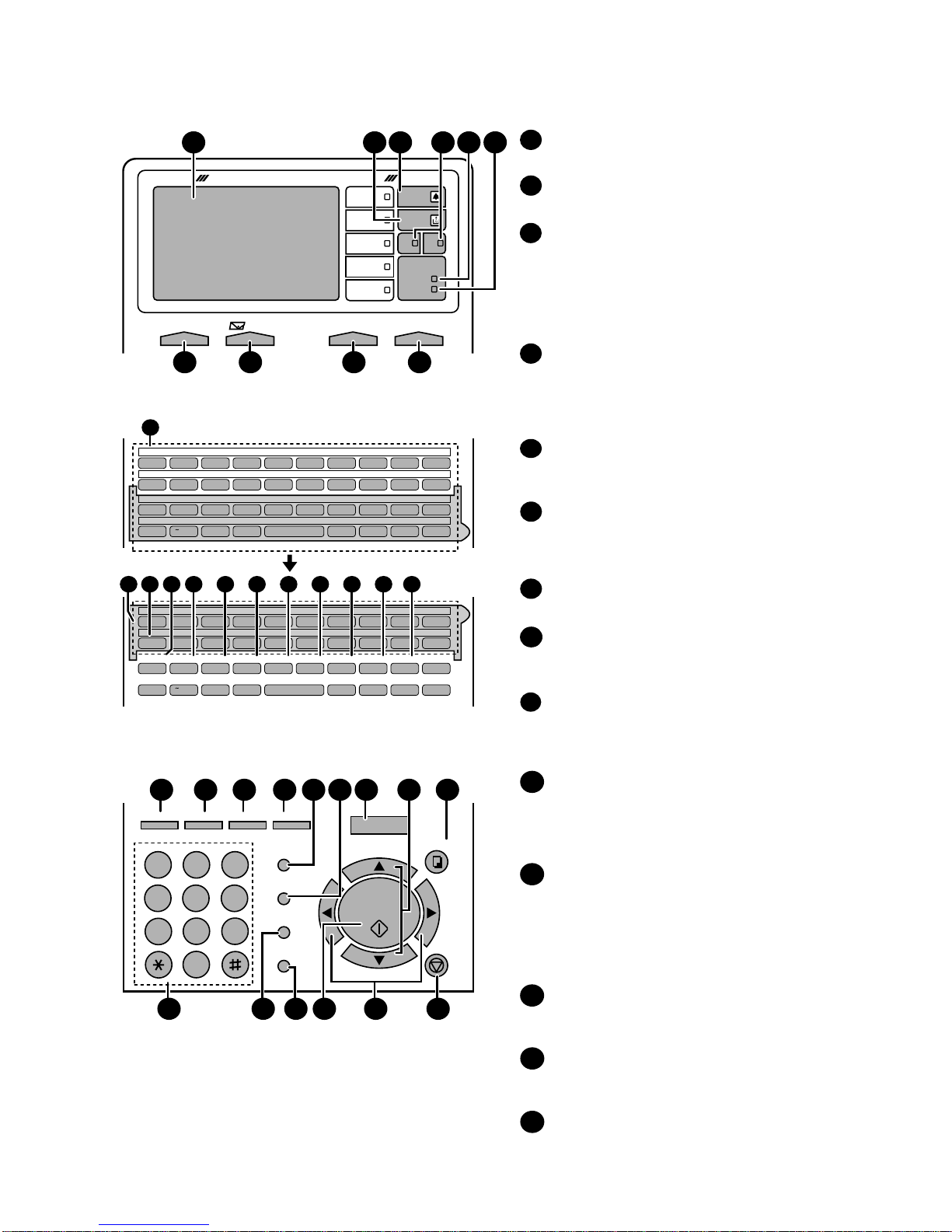
Automatic dialing: Conventional Auto Dialing:
Rapid Key Dialing: 59 numbers
Speed Dialing: 200 numbers
Personal Auto Dial Books: 40 books
(59 Rapid Keys, 16 Speed Dial
numbers per book)
Memory size* : 16 MB (approx. 1,000 pages)
Optional memory: FO-8MK (8 MB;
approx. 500 pages)
Modem speed: 33,600 bps (max.) with automatic
fallback to lower speeds
Transmission time* : Approx. 2 seconds
Toner cartridge yield: Initial starter cartridge (included with
(continuous printing, fax machine): Approx. 3000 pages
4% page coverage, Replacement cartridge (FO-50ND):
letter paper) Approx. 6000 pages
Drum cartridge yield: Initial starter cartridge (included with
fax machine): 20,000 pages (avg.)
Replacement cartridge (FO-47DR):
20,000 pages (avg.)
Resolution: Standard: 203 x 98 lines/inch
(8 x 3.85 lines/mm)
Fine/Halftone: 203 x 196 lines/inch
(8 x 7.7 lines/mm)
Super fine: 203 x 391 lines/inch
(8 x 15.4 lines/mm)
Ultra fine: 406 x 391 lines/inch
(16 x 15.4 lines/mm)
Halftone (grayscale): 64 levels
Automatic document feeder: Letter paper (20 lb): Max. 50 pages
Legal paper: Max. 20 pages
(Note: 11” x 17” paper must be loaded
one page at a time.)
Paper capacity: 750 sheets (20 lb)
(500-sheet cassette available as option)
Compression scheme: MMR, MR, MH, Sharp (H2), JBIG
Applicable telephone line: Public switched telephone network
Compatibility: ITU-T (CCITT) G3 mode, Super G3
mode
Printing resolution: Horizontal: 406 dots/inch (16 dots/mm)
Vertical: 391 lines/inch (15.4 lines/mm)
600 x 600 dpi (Network Print: FO-NP1)
Input document size: Automatic feeding:
Width: 5.8 to 10.1” (148 to 256mm)
Length: 5.0 to 14.3” (128 to 364 mm)
Manual feeding:
Width: 5.8 to 11.0” (148 to 279 mm)
Length: 5.0 to 19.0” (128 to 483 mm)
Effective scanning width: 10.1” (256 mm) max.
Effective printing width: 8.0” (203 mm) max.
Printing speed: 16 ppm
Reception modes: Auto/Manual
Instascan speed: 1.3 sec/page (letter paper; scan time
only, excludes document feeding time)
Full Dual Access: Yes
Copy function: Single/Multi/Sort (99 copies/page)
Power requirements: 120 VAC, 60 Hz
Operating temperature: 50 - 86°F(10 - 30°C)
Humidity: 20 to 85 % RH
Power consumption: Stand-by: 9 W
Stand-by(all options installed: 16W
Maximum: 800 W
Dimensions: Width: 21.5” (546 mm)
Depth: 16.2” (412 mm)
Height: 17.0” (431 mm)
(Not including paper tray or attachments)
Weight: Approx. 48.5 lbs. (22.0 kg)
(Not including supplies paper tray or
attachments)
* Based on ITU-TTest Chart #1 at standard resolution, excluding time for
protocol signals (i.e., ITU-T phase C time only).
1 – 1
Toner cartridge Replacement cartridge 6,000 prints User
(FO-50ND) (at Letter/4% chart)
Drum cartridge Replacement cartridge 20,000 prints User
(FO-47DR) (at Letter/4% chart)
Paper feed Transfer roller
(Refer to the P/G No. 10-8)
50,000 prints Service Engineer
(0KW4127410302)
Fuser Fusing unit
(Refer to the P/G No. 9-14)
50,000 prints Service Engineer
(0KW4127035501)
Paper transport
Paper transfer roller (Refer to the P/G No. 8-6)
Cleaning as needed ———————
(0KW4127300101)
[2] Life of consumable
Section Part Estimated Life Replaced by

FO-DC600U
[3] Operation panel (1)
Display
This displays messages and prompts to help you operate
the machine.
TONER indicator
This blinks when the toner cartridge nears empty, and lights
steadily when the toner cartridge needs replacement.
ALARM indicator
This blinks when one of the paper sources is empty or the
drum cartridge is near the end of its life (printing is still
possible). This lights steadily when the drum cartridge has
reached the end of its life, all paper sources are empty, the
print compartment cover is open, or a paper jam has
occurred (printing is not possible). A message will appear in
the display to indicate the problem.
1
2
3
Q / ! W / " E / # R / $ T / % Y / & U / ' I / ( O / ) P / =
SYMBOL
A / |S D F G / { H / } J / [ K / ] L / +
Caps Lock
Z / < X / > C V B N / * M / ? @ .com
SHIFT / ^ / / \ ; / : Space _- . / , DEL
Q / ! W / " E / # R / $ T / % Y / & U / ' I / ( O / ) P / =
SYMBOL
A / |S D F G / { H / } J / [ K / ] L / +
Caps Lock
PAGE COUNTER
CONFIDENTIAL
TIMER
COVER SHEET
LIFE
MEM.STATUS
REPORT
DOCUMENT
Z / < X / > C V B N / * M / ? @ .com
SHIFT / ^ / / \ ; / : Space _- . / , DEL
01 02 03 04 05 06 07 08 09 10
11 12 13 14 15 16 17 18 19 20
40 41 42 43 44 45 46 47 48 49
50 51 52 53 54 55 56 57 58 59
21 22 23 24 25 26 27 28 29 30
31 32 33 34 35 36 37 38 39
JKL
ABC
1
DEF
WXYZ
9
GHI
45
MNO
6
PQRS
7
TUV
8
0
2 3
OPER
PERSONAL
BOOK
SPEED DIAL
REDIAL
SPEAKER
JOB STATUS
DUPLEX SCAN
PRIORITY
BROADCAST
MENU
UP
ZA
DOWN
START/
ENTER
COPY/HELP
STOP
22 2923 24 25 30
31 35 3632 34
28
33
2726
DATAlight
This blinks when the machine is receiving a print job over
the network (only when the network printer option is
installed).
FAX 1 / FAX 2 lights
When the dual line option is installed, FAX 1 lights when
Line 1 is being used and FAX 2 lights when Line 2 is being
used. When the dual line option is not installed, only FAX 1
lights when the telephone line is being used (the FAX 2
light does not operate).
4
5
ON LINE light
When this light is on, the machine can receive data (print
jobs) over the network. The light is turned on or off with the
ON LINE key. (Only available when the network printer
option is installed).
CONTRAST key
Press this key to adjust the contrast before sending or
copying a document.
E-mail key
Press this key to send a scanned document to an e-mail
recipient. (Only available when the network scanner option
is installed).
RESOLUTION key
Press this key to adjust the resolution before sending or
copying a document. An indicator will light next to the
selected setting (HALFTONE, STANDARD, FINE, SUPER
FINE or ULTRA FINE).
ON LINE key
Press this key to select whether the machine is online or
off-line (the ON LINE light is on when the machine is
online). The machine must be online to receive print
jobs over the network. (Only available when the network
printer option is installed).
6
10
9
8
7
11
Rapid Dial Keys
Press one of these keys to dial a fax number automatically,
or specify an e-mail recipient if the network scanner option
is installed. Note that you must attach the Rapid Key labels.
When navigating through the display menu, a Rapid Key
can also be pressed in place of the numeric keys to enter
a two-digit number (for example, you can press Rapid Key
01 to enter the number "01").
SYMBOL key
When entering a name, press this key to enter the symbol
on a letter key (the character to the right of the slash).
Press the key again to turn off symbol entry mode.
PAGE COUNTER key
Press this key to include a slash and the total number of
pages after each page number on the pages of a
transmitted document.
CONFIDENTIAL key
Press this ke
y
to send or
p
rint out a confidential document.
14
12
13
SUPER FINE
DOCUMENT COMMUNICATION SYSTEM
HALF TONE
CONTRAST RESOLUTION
e-mail
ON LINE
STANDARD
FINE
ULTRA FINE
DATA
ON LINE
Network
FAX2FAX1
ALARM
TONER
1 3 4 5 62
7 98 10
LINE
11
11 14 15 16 17 18 19 2012 13 21
1 –2

FO-DC600U
1 –3
15
TIMER key
Press this key to set a fax operation to be performed
automatically at a later time.
COVER SHEET key
Press this key to include a cover sheet when sending a fax.
LIFE key
Press this key, followed by , to check the total number of
pages printed by the fax machine. (Press to return to the
data and time display.
MEM. STATUS key
Press this key to check the status of fax transmission jobs,
copy jobs, and fax receptions. This key can also be used to
cancel a job.
REPORT key
Press this key to print out a report on the most recently
completed transmission or reception.
DOCUMENT key
Press this key to transmit a document directly from the feeder
without reading it into memory.
16
18
19
17
20
23
22
START/
ENTER
STOP
JOB STATUS key
Press this key to display the FAX-STATUS screen, which
shows information on the fax job that is currently in progress.
If the dual line option is installed, the fax status will appear
separately for each line. If the network printer option is
installed, the NETWORK PRINT STATUS screen showing
information on current printer activity will appear following
the FAX STATUS screen (note that "IDLE" will appear if a
print job has been executed but is not yet being printed).
To cancel a job that is in progress, display the job in the
status screen and then press . To move through each of
the screens and return to the date and time display, press
one or more times as needed.
DUPLEX SCAN key
Press this key to transmit or copy a two-sided document.
PRIORITY key
Press this key when you need to transmit a document ahead
of other documents waiting in memory for transmission.
BROADCAST key
Press this key to send a document to a group of fax
machines, or to a group of e-mail recipients if the network
scanner option is installed.
24
25
26
27
STOP
JOB STATUS
PERSONAL BOOK
Press this key to use or store an auto-dial number in a
personal book. If the book has a passcode, enter the
passcode; otherwise, select the book with or and
press .
SPEED DIAL key
Press this key to dial a Speed Dial number.
MENU key
Press this key to select special functions and setting.
UP and DOWN arrow keys
Volume setting: Press these keys to change the speaker
volume when the SPEAKER key has been pressed, or the
ringer volume at any other time.
MENU key settings: Press these keys after pressing the
MENU key to scroll through the MENU key settings.
29
28
START/
ENTER
Dial keypad (numeric keys)
Use these keys to dial and program fax numbers.
REDIAL key
Press this key to automatically redial the last number dialed.
SPEAKER key
Press this key when transmitting a document by Normal
Dialing to listen to the line and verify the response of the
receiving fax machine.
START/ENTER key
Press this key to begin fax transmission when using Speed
Dialing, Direct Keypad Dialing, or Normal Dialing. This key is
also used to select settings in the MENU key menu and
complete entries when storing names and numbers.
Left and right arrow keys
Auto-dial numbers: Press these keys to search for an
auto-dial number when sending a fax.
STOP key
Press this key to cancel an operation before it is completed.
31
32
33
34
35
36
COPY/HELP key
When a document is in the feeder, press this key to make a
copy of a document. At any other time, press this key to print
out the Help List, a quick reference guide to the operation of
your fax machine.
30
LINE key
When the dual line option has been installed, press this key
before dialing to select the line.
21
Operation panel (2)
[4] Transmittable documents
Refer to the service manual of FO-DC500U.
[5] Installation
Refer to the service manual of FO-DC500U.
[6] Quick reference guide
Refer to the service manual of FO-DC500U.

FO-DC600U
[7] Installing the Dual Line Kit (FO-60DL)
Note: The FO-60DL Dual Line Kit cannot be installed if the FO-NP1
Network Printer Kit is installed.
Important! The following procedure is to be performed only by a quali-
fied service technician. Be sure to turn off the power, unplug the power
cord,andunplugthetelephone line before proceeding. In addition, touch
a grounded piece of metal to discharge any static electricity that may be
on your body. Make sure that an extension phone is not connected to
the machine.
1
Press the cover release to open the print compartment cover.
2
Remove 6 screws from the rear cover.
(Remember which screw secures the small cover on the left side of
the rear cover, as it must be replaced in the same position).
Remove the small cover, and then remove the screw underneath.
Remove the rear cover.
3
Remove 6 screws and then remove the metal plate.
4
Remove the screw that holds the small side plate to metal plate that
was removed Step 3. Slide the small side plate up and remove it
from the metal plate. (Note: The small side plate is not no longer
needed, however, the screw is used again in “b” of Step 5.)
6
Replace the metal plate and secure with screws in the order shown.
7
Attach the dual line control board.
a. Insert the bushing into the hole in the dual line control board from
the outer side and secure it with the collar on the inner side.
b. Insert the winged end of the pin spacers into the metal plate, with
wings extended out vertically.
c.Attach the board so that the connector inserts into the connector in
the metal plate. Make sure that the pin spacers go into the holes
in the board. Secure the board with the 18 mm screw (which goes
into the bushing) and the remaining 6 mm screw. Tighten the
screws in the order shown.
1 – 4
8
Fasten the band to the core as shown and cut off the excess end.
Insert the cable through the core and wind it around the core twice.
5
a. Attach the LIU board to the metal plate, positioning the modular
jacks as shown. The bottom edge of the board should fit into the
slots indicated by the arrows. Secure the LIU board with two of the
6 mm screws.
b. Attach the provided metal side plate.
a
b
1
2
3
4
b
a
c
1
2

FO-DC600U
[8]
Installing the Third Paper Cassette (FO-CS1)
Important! Be sure to turn off the power and unplug the power cord
before proceeding.
1
Removethe packing material and tapefrom the third papercassette.
2
Remove the covers from the sides of the second cassette (the cas-
settealreadyinstalled on the machine), using a flat-headscrewdriver
to pry each of the catches at the bottom of the covers free (2 on the
right cover, 3 on the left cover).
1 –5
F
Replace the rear cover.
(Be sure to replace the screw that secures the small cover in the
same position, as it is for plastic.)
9
Connect the cable to the LIU board and the dual line control board.
Secure the core band with the 10 mm screw.
For plastic
G
Affix the “”LINE 2”label above the new jack.
LINE 2
3
Insert the green gear into the third cassette as shown. The side of
the gear that has the small thirdly gear should face the inside of the
cassette, and should fit onto the metal shaft. Push the gear in until
the tab on the outer side goes into the slot on the metal shaft. (Note:
The gear is only used in the third cassette.)
4
Place the machine on top of the third cassette, and remove the small
cover from the rear of the second cassette. Connect the 10-pin cable
as shown, and insert it behind the guide indicated by the white arrow.
5
Change the positions of the connectors on the circuit board of the
third cassette as shown (do not change the connectors on the sec-
ond cassette). Replace the small cover on the rear of the second
cassette, and attach the provided small cover on the rear of the third
cassette.
6
Attach the large support plate and then the small support plate to the
right side of the cassettes. Use 6 mm screws for the holes marked
with “A”, and 10 mm screws for the holes marked with “P”. Secure
the screws in the order indicated by the numbers.
A2A2 A1A1
P3P3A3A3
A3A3
A4A4 P4P4
A4A4
2
1
7
Attach the support plate to the left side of the cassette. Use 6 mm
screwsforholesmarkedwith“A”,and10mmscrewsforholesmarked
with “P”, securing the screws in the order indicated by the numbers.
(Note that the top hole on the right does not require a screw.)
A1
A3
A4
A2
P6 P5

FO-DC600U
Output Voltage limits Note
+5V MAIN 4.947V~5.25V CN5 7pin ↔8pin
+24V SUB 23.04V~24.96V CN5 1pin ↔2pin
CHAPTER 2. ADJUSTMENTS
[1] Adjustments
General
Sincethefollowingadjustments and settings are provided for this model,
make adjustments and/or setup as necessary.
1. Adjustments
Adjustments of output voltage (FACTORY ONLY)
1. Install the power supply unit in the machine.
2. Set the recording paper and document.
3. When the document is loaded, power is supplied to the output lines.
Confirm that outputs are within the limits below.
Output voltage settings
Fig. 1
POWER
SUPPLY
PWB
CONTROL PWB
PRINTER PWB
HIGH VOLTAGE
PWB
CN5 CN1
CNPW1 CNPRT1
1
112 130
CN1
130
12
CN1
VR51
[DO NOT TOUCH!]
1
10
CN7 CN4
1
8
1
10
1
8
2
DISPLAY:
KEY:
22: DIAL MODE
1=TONE, 2=PULSE
(step 2) Select "DIAL MODE".
2
2
(step 1) Select "OPTIONAL SETTING".
DISPLAY:
DISPLAY:
DISPLAY: TONE SELECTED
KEY:
MENU 4
KEY:
4:OPTIONAL SETTING
ENTER #(01-36, , )
KEY:
22: DIAL MODE
KEY:
KEY:
DISPLAY:
(step 4) End, using the "STOP" key.
(step 3) Select, using "1" or "2".
(step 2) Select "DIAL MODE".
1
2
PULSE SELECTED
2
STOP
1
DISPLAY:
KEY:
1: LINE-1
1=TONE, 2=PULSE
Select line using "1" or "2"
2
DISPLAY:
KEY:
2: LINE-2
1=TONE, 2=PULSE
<With optional line unit>
22: DIAL MODE
1=LINE-1, 2=LINE-2
2. IC protectors replacement
ICPs (IC Protectors) are installed to protect the CIS unit, panel PWB
unit,TX motor drive circuit and verification stamp drive circuit. ICPs pro-
tect various ICs and electronic circuits from an overcurrent condition.
The location of ICPs are shown below:
(1) F1 (ICP-S0.5) F2 (ICP-S1.0) is installed in order to protect IC’s from an
overcurrent generated in the CIS unit. If F1 or F2 are open, replace it with a
new one.
(2) F5 (ICP-S1.0) is installed in order to protect IC’s from an overcurrent gener-
ated in the panel PWB unit. If F5 is open, replace it with a new one.
(3) F100 (ICP-S1.0) is installed in order to protect IC’s from an overcurrent gen-
erated in the verification stamp drive circuit. If F100 is open, replace it with a
new one.
(4) F101 (ICP-S1.8) is installed in order to protect IC’s from an overcurrent gen-
erated in the TX motor drive circuit. IfF101 is open, replace itwith a new one.
(5) F102 (ICP-S0.7) is installed in order to protect IC’s from an overcurrent gen-
erated in the LCD drive circuit. If F102 is open, replace it with a new one.
In addition to the replacement of F1, F2, F5, F100, F101 andF102 the factor
causing F1, F2, F5, F100, F101 and F102 to open must also be repaired. If
not, F1, F2, F5, F100, F101 and F102 will open again.
Replacement parts
ICP-S0.5 (Sharp code: VHViCPS05//-1)
ICP-S0.7 (Sharp code: VHViCPS07//-1)
ICP-S1.0 (Sharp code: VHViCPS10//-1)
ICP-S1.8 (Sharp code: VHViCPS18//-1)
Fig. 2
CONTROL PWB
(TOP SIDE)
CNLIU1
CNSP1
CNSEN1
CNCIS1 CNPN1
CNSTP1 F1/F2/F5:Top side
F100/F101/F102:Bottom side
CNTXM1
IC3
1
1
8
10 1 11214
27
228
F1 F2 F5 F100 F101
2
CNPW1
12 1
F102
2 – 1
Connector CN4
No.
Pin No. CN1
1 11 +5V
2 10 CH LREM
39TVR
4 8 T MON V
5 7 T MON I
6 6 B VR
7 5 V REM
8 4 C MON
93MG
10 2 +24V
Connector CN1
No.
Pin No. CN7
1 +24V MAIN
2MG
3DG
4DG
5 +5V MAIN
6 +5V MAIN
7 HEATER ON
8 H-RELAY OFF
Connector CN5
No.
Pin No. CNPW1
1 +24V SUB
2MG
3MG
4MG
5 +24V MAIN
6 +24V MAIN
7 +5V MAIN
8DG
9DG
10 DG
11 +5V MAIN
12 +5V MAIN
3. Settings
(1) Dial mode selector
OPTION SETTING: DIAL MODE (Soft Switch No. SW2 DATANo. 1 for
Line-1 and SW24 DATA No.1 for Line-2 with Optional Dual Line Kit)
Use this to set the fax machine to the type of telephone line you are on.
• The factory setting is "TONE".

FO-DC600U
[2] Diagnostics and service soft switches
1. Operating procedure
Two kinds of diagnoses are supported.
1-1. Fax diagnosis
This diagnosis is concerned with the main body of fax which is used for
production and service support.
Entering the diagnostic mode
1-2. Print diagnosis
This diagnosis is concerned with the print which is used for production
and service support.
Entering the diagnostic mode
Memory clear when power is turned on
Pressing the START and STOP keys, turn on the main power, and the
following message will be displayed.
1 =All the data will be deleted including initially registered data.
2 = Delete the image file to be used in transmission. This will delete all
thedata related to communicationsuch as reserved transmission or
intercepting. However, the data initially registered will not be de-
leted.
3 = Memory will not be cleared and the machine enters stand-by mode.
Press , and the following
display will appear.
MENU
9 8 6
PCU ROM VER.:
(Diag
•
specifications)
MENU
986
START
01
AREA PRINT MODE 1
START
02
CHECK PATTERN 1
START
03
CHECK PATTERN 2
START04
CHECK PATTERN 3
START05
CHECK PATTERN 4
START06
PAPER FEED AGING 1
START07
PAPER FEED AGING 2
START
START
08
BIAS ADJUST MODE2
START
09
LIFE SET MODE
START
START
Then press the key. Select the desired item with the
key and the key or select with the rapidkey.
Enter the mode with the key.
START10
LIFE ALL CLEAR
START11
LIFE ENTRY MODE
PCU ROM Ver.:
START12
LIFE CLEAR MODE
MEMORY CLEAR ?
1 = ALL , 2 = IMAGE , 3 = NO
MENU
9 8 7
STARTA SOFT SWITCH MODE
START
B PRINT AREA
START
C ROM & RAM CHECK
START
D AUTO FEEDER MODE
STARTE AGING MODE
START
F PANEL CHECK MODE
START
G OPTICAL ADJUST MODE
START
H PRODUCT CHECK
START
ISIGNAL SEND MODE
START
JCOMM. CHECK MODE
START
KMEMORY CLEAR MODE
START
LFLASH MEMORY CHECK
START
MALL FAX/TEL. ENTRY MODE
START
START
N
O CONF. PASSCODE
START
PSIGNAL SEND MODE 2
START
Q
TA70
START
DEPT. PASSCODE
MENU
9 8 7
Press , and the following
display will appear.
START
Then press the key. Select the desired item with the key
and the key or select with the rapid key.
Enter the mode with the
START
key.
(Diag •specifications)
MEMORY SET MODE
START
RSTAMP AGING MODE
START
SDIAL TEST MODE
START
T
U
COPY DIAG MODE
LCD CHECK MODE
VPERSONAL BOOK LIST
START
WFONT LIST PRINT MODE(*)
START
START
XNO FUNCTION
START
1st
Line
2
nd
Line
3rd
Line F/W version
4th
Line NIC board version
5th
Line PCL board version
6th
Line
7th
Line Memory size
8th
Line GATE arrayA/B version
9th
Line
FAX
: TA70
NIC
:
x.xxx
PRN
:
xxxx
PRN
MEMORY
SIZE
=
16(MB)
GAA
:
ESx
GAB
:
ESx
*: FONT LIST PRINT MODE can be used only when the
network function is effective.
2 –2

FO-DC600U
2. Diagnostic items description
2-1. Fax diagnosis
A) Soft switch mode
In this mode, the soft switch are set and the soft switch list is printed.
•OFF to ON of department control function during use of image
memory.
(Note: In the existing set, the department control function is set
from OFF to ON when the timer communication (including the
batch sending) or the memory hold is set.)
•ON to OFF of continuous serial polling function when the con-
tinuous serial polling is started.
(Note: In the existing set, "ON to OFF of the continuous serial
polling function when the continuous serial polling is registered"
has been applied, but the conditions are now moderated. How-
ever, registration is impossible tothe program of the new continu-
ous serial polling when the continuous serial polling function is
OFF.)
•In addition, change of all soft switches during communication
1
Switch number selection
•Press START key for setting of the next soft switch. If the soft
switch number is the final, pressing START key will exit the soft
switch mode.
•Enter two digits of a soft switch number to set the switch number.
If a switch number of nonexistent soft switch is entered, key error
buzzer sounds to reject the input.
2
Data number selection
The cursor position shows the data to be set.
Pressing # key or →key moves the cursor to the right. If, however,
the cursor is on data number 8, pressing # key or →key shifts the
cursor to data number 1 of the next switch number. If the switch
number is the final, pressing # key or →key will exit the soft switch
mode.
Pressing key or ←key moves the cursor to the left. If, however,
the cursor is on data number 1, pressing key or ←key shifts the
cursor to data number 1 of the former switch number. If the switch
number is 1, pressing key or ←key will not move the cursor and
the error buzzer will sound.
3
Data setting method
Pressthe MENU key, andthe data at the positionof the cursor will be
reversed to 0 when it is 1, or to 1 when it is 0. (If the soft switch can
be changed at the bit (Refer to
6
.), the error buzzer will sound with
the process not received.)
4
Outputting method of soft switch list
In the soft switch mode, press the REPORT key, and the soft switch
list will be output.
If the recording paper runs out or is clogged, the key error buzzer will
sound with the process not received.
5
Storage of data
In the following case, the data of the soft switches set will be stored.
•It is shifted to set the next soft switch by pressing the START
switch.
•It is shifted to set the next soft switch with the [#] key.
•It is shifted to set the last soft switch with the [ ] key.
•It is shifted to set another soft switch by inputting two digits as the
switch number. (When 2 digits are completely input.)
•Output of the soft switch list is started.
6
Inhibition of data change
(This is also applicable for the optional setting.)
In the following case, it is inhibited to change the data with the key
error buzzer.
•Switching ON/OFF of ECM during the use of image memory.
•OFF to ON of telephone billing function which is using the image
memory is used (Note: In the existing set, the telephone billing
codefunction is specified from OFFtoON when the timer system
communication (including the batch communication) is set.)
Here,thememory is usable when the telephone billing code func-
tion is on. It can be set from ON to OFF while the memory is
used. However, if setting is practically changed even once, it can
not be returned from OFF to ON.
S O F T S W I T C H M O D E
S W 0 1 = 0 0 0 0 0 0 0 0
Soft switch mode screen
Switch
No. 1
2
3
4
5
6
7 :DATA No.
8
Data
S O F T S W I T C H M O D E
S W 0 1 = 0 0 0 0 0 0 0 0
E N T E R L A S T D I G I T
S W 1
S O F T S W I T C H M O D E
S W 1 6 = 0 0 0 1 0 1 1 0
1 6
Cursor
ROM SRM DRM1 DRM2
••••
ROM SRM DRM1 DRM2
P P P E
Display during check Display after check
P=PASS E=ERROR
2 –3
No. Device checked
Number of buzzer sound
Remarks
1
ROM (PROGRAM FLASH)
<Short sound> 1 time <Short sound>:
2 SRAM <Short sounds> 2 times
0.5 sec.ON / 0.5 sec.OFF
3 Main D-RAM1 (*1) <Short sounds> 3 times <Long sounds>:
4 D-RAM2 (*2) <Short sounds> 4 times 1.0 sec.ON / 0.5 sec.OFF
5——
*1: Work memory (SDRAM 8 MB)
*2: Page memory (SDRAM 16 MB)
(Example of display) In case that DRAM2 is erroneous.
B) Print area
According to the size of the specified sheet, the effective printing area is
printed.
C) ROM & RAM check
This is an item to check if the loaded memory device acts normally.
•The memory devices shown in the following table are checked.
•In case that an error occurs in the device check, the alarm buzzer
shown in the table sounds.
Check device and alarm buzzer
•After the check is complete, the result is outputted.
•In case that an NIC and a PCL board are mounted, the version
information of the board is also printed on the result.
D) Auto feeder mode
Byexecuting the document insertion anddischarge, the automatic feed-
ing function can be checked. And the document sensor can be checked
as well.
1
Set the document
Beforepressing the “START”key,only the document sensor check is
carried out. And as the document sensor is ON, the document size
(A4/B4) and the sensor information (A4/B4/ORG) are displayed.
2
Theautomaticfeedingstartsby pressing the “START”key.This mode
ends when the document ends, and the result is printed.
AUTO FEEDER MODE
( )
AUTO FEEDER MODE
B4 (A4 B4 ORG)
After setup of the document
Only the sensor which is
activated (fallen down) is displayed.)
The paper sheet size (A4/B4) is
displayed.

FO-DC600U
E) Aging mode
This is a mode to execute the copying action and the check pattern
printing action once every 60 minutes and continue the action until 10
sheets are outputted in total.
1
The printing action on the 1st sheet starts by pressing down the
“START”key and entering the mode. When document is set at the
time of the mode start-up the copy action is carried out, and when
the document is not set the “check pattern 1”of the print dialog is
printed.
2
The number of printouts is displayed after printing.
F) Panel check mode
This is to check that each key acts normally and this is displayed on the
LCD according to the key input. And during execution, the document
readinglampis ON.After inspection start, the LEDs lightonsequentially.
At the mode end with the “STOP”key, all of them go OFF. As to the test
result, it is printed out after the mode end.
When the “NUMERIC”key is pressed during the panel check ex-
ecution,sendingoftheDTMFsignalcorrespondingto the key starts,
andwhenanotherkeyispressedsendingoftheDTMFsignal stops.
(Softswitch change is required. SW80 No.6: 0 →1)
•After inputting all the keys, input the “STOP”key at last, and then the
result is displayed.
a) In case that all the keys are pressed.
•Until the STOP key is pressed, all black 4-split sequential display is
performed.
•After the mode end, the test result is printed.
b) In case that there is a key that is not pressed.
•Until the STOP key is pressed, all black 4-split sequential display is
performed.
•After the mode end, the test result is printed.
G) Optical adjust mode
The optical system is adjusted.
•Bypressingdownthe“START”key,the document reading lamp “100%:
ON”is turned ON.
H) Product check
This is a dialog used in the production process and a mode to execute a
specific mode in the series of the flow.
After the mode end, the rest result as to the checked items is printed.
•After moving to the mode, the following actions are sequentially ex-
ecuted.
1
Memory clear (Same as Diagnosis K)
2
Panel check (Same as Diagnosis F)
3
ROM & RAM test check (Same as the Diagnosis C)
4
Test result print
Memory clear printing
Panel check result printing
ROM & RAM test result printing
5
Print area (The specification of each item is the same as the specifi
cation of the simple mode.)
I) Signal send mode
It can be used to check the modem.
When the START key is pressed, silence signal (make loop) will be
executed. The following signals are sent by pressing the START key
thereafter.
[ 1] No signals (make loop)
[ 2] 4800BPS (V. 27ter)
[ 3] 14400BPS (V. 33)
[ 4] 12000BPS (V. 33)
[ 5] 14400BPS (V. 17)
[ 6] 12000BPS (V. 17)
[ 7] 9600BPS (V. 17)
[ 8] 7200BPS (V. 17)
[ 9] 9600BPS (V. 29)
[10] 7200BPS (V. 29)
[11] 4800BPS (V. 29ter)
[12] 2400BPS (V. 29ter)
[13] 300BPS (FLAG)
[14] 2100Hz (CED)
[15] 1100Hz (CNG)
J) Comm. check mode
1
Turn on the Line Monitor. (SW7 No.7, SW29 No.7)
2
Turn off the Cover Sheet Function. (SW2 No.6, SW24 No.6)
3
Set Line Equivalence at 0 km. (SW8 No.1/No.2, SW30 No.1/No.2)
4
Set the copy cut off mode (SW75 No.2) to “Continue”
5
Set the ringer volume (SW62 No.5/No. 6) to OFF.
After the check, it is necessary to be sure to return the aforementioned
soft switches into the initial state.
(Clear the memory with the diagnosis.)
K) Memory clear mode
Clear the back-up memory to initialize the soft switches.
The Flash Memory will be initialized. Then, the initialized list be output.
1
Memory clear is executed.
2
The result that says initialized is printed.
NOTE: The life counter, and the adjustment values of the top void and
the large LCD contrast are not cleared.
2 –4
PANEL CHECK MODE
ALL KEY OK !!
PANEL CHECK MODE
KEY ERROR !!
L) Flash Memory check
This is a mode to check that the flash memory acts normally. The flash
memories shown in the following table are checked.
•NAND-Flash (optional) is valid only when the optional memory is
mounted.
1
The NOR flash memory test is executed.
2
The concerned alarm buzzer sounds only when the error occurs.
3
The NAND flash memory test is executed.
4
The concerned alarm buzzer sounds only when the error occurs.
5
The result is printed.
NOTE:
•During operation of this diagnosis, dual operation is not possible at all.
•Ifthisisexcessively repeated, it will shorten the life of the flashmemory.
NOR FLASH CHECK
S ———————E
No. Flash memory
Number of buzzer sound
Remarks
1
NOR-Flash (Standard)
<Long sound> 1 time <Short sound>:
2
NAND-Flash (Standard)
<Long sounds> 2 times
0.5 sec.ON / 0.5 sec.OFF
3
NAND-Flash (Option)
<Long sounds> 3 times <Long sounds>:
4——1.0 sec.ON / 0.5 sec.OFF
5——
NAND FLASH CHECK
S ———————E

FO-DC600U
M) All FAX/TEL. entry mode
This is a function to copy the FAX and TEL numbers registered in the
one-touch dialing (RAPID) key [01] to the all one-touch dialing (RAPID)
key and the all abbreviated number (SPEED DIAL) to simplify the FAX
and TELnumber registration at the time of aging. (Only the E-MAIL can
be used for the network models.)
1
Copy the FAX/TEL number or the E-MAIL stored in the RAPID key
[01] to all RAPID keys.
2
Copy the FAX/TEL number or the E-MAIL stored in the RAPID key
[01] to all SPEED DIAL numbers.
3
Ifthe chain dial is not setforthe RAPID key,orRAPID key [01] stores
the E-MAIL, the RAPID keys [02] –[59] and all SPEED DIAL num-
bers are stored in the group number [01].
4
Enter all registered one-touch send (RAPID) keys and speed dial
numbers (SPEED DIAL) on the personal books [01] - [10].
Following this, set the password registration and the password
setting to ON, and set the TTI setting to OFF.
The call-receiver names and book names are specified as follows:
(The letters after 16th letter of the call-receiver’s name registered in the
one-touch dialing [01] are cut off.)
NOTE: Before entering this mode, a FAX/TEL number or an E-MAIL
must be stored in the RAPID key [01]. (This program will not be
executed if there is no data stored, or otherwise a program or a
group is registered.)
N) Dept. passcode
The department passcode list is printed.
O) Conf. passcode
The confidential passcode list is printed.
Differing from printing of one box alone soon after registration, the con-
fidential passcodes of all boxes are printed.
P) Signal send mode 2
The signals concerned with V.34 & V.8 are checked. It can be used to
check the modem.
When the START key is pressed, silence signal (make loop) will be
executed. The following signals are sent by pressing the START key
thereafter.
[ 1] No signal (make loop)
[ 2] 33600BPS (V. 34)
[ 3] 31200BPS (V. 34)
[ 4] 28800BPS (V. 34)
[ 5] 26400BPS (V. 34)
[ 6] 24000BPS (V. 34)
[ 7] 21600BPS (V. 34)
[ 8] 19200BPS (V. 34)
[ 9] 16800BPS (V. 34)
[10] 14400BPS (V. 34)
[11] 12000BPS (V. 34)
[12] 9600BPS (V. 34)
[13] 7200BPS (V. 34)
[14] 4800BPS (V. 34)
[15] 2400BPS (V. 34)
[16] 0 - 300BPS (V. 34)
[17] ANSam
Q) Memory set mode
The set and dump list of the memory content is output.
•The address (8 digits (P) generally including the bank information is
input, and the data of 2 digits is continuously input.
Inputting is done in the hexadecimal mode. The ten-key is used for 0
through 9, and the alphabetic keys A (RAPID 01 through 06) are
used forA through F.
•During data inputting, the address can be moved forward and back-
ward one byte by one byte with " " and "#". (The address prior to the
address 0 is looped as the maximum address.)
•The Validity of the address is not checked.Accordingly, writing/ read-
ing operations are possible in the address of the memory not as-
signed, the address of ROM and so on.
(However, as practical, writing is not done, and the data content runs
short each reading.)
Though writing is possible in the flash memory, a little time is re-
quired.
It is also necessary to take care that the life of the flash memory is
excessively shortened if much data is written in the flash memory.
Since it may run away depending the written content, take minute
care for the writing address.
•When the REPORT key is input, the memory dump list is produced
from the displayed address (here, it is limited at the 16-byte bound-
ary address (address with end 0) which does not exceed the speci-
fied address and is just in front.). The dump list is output to a maxi-
mum of 99 pages. If any data of one page can be repeatedly devel-
oped and printed, the list is sufficient. But it is not desired that the
content of plural pages are developed in the memory once and are
then printed. If the STOP key is pressed, it will pass to the diagnosis
after the page which is now being printed is completed printed.
If the address exceeds the maximum address, it will return to the
address 0 and printing will be continued.
R) Stamp aging mode
This is a mode to execute the continuous drive aging of the Verification
stamp.
1
Set the document and press down the “START”key and the
continuous drive of the Verification stamp starts.
2
Send the document at the interval of 10 mm and stamp the
Verification stamp continuously. The total number of times of
Verification stamp printing after entering this mode is displayed on
the display.
•Displayed screen during execution
3
Bypressingdown the “STOP”key during the action, or when nomore
document is left, the continuous drive of the Verification stamp stops.
NOTE:
•In case that the document is not set, this cannot be executed.
•The normal action aging that one Verification stamp is pressed on one
sheet of document is executed in the normal copying.
Rapid R XX XX : Rapid key send
SPEED DIAL S XXX XXX
: Speed dial number
Personal book BOOK XX XX : Book number
2 –5
MEMORY SET MODE
AD = 00000000
Cursor
MEMORY SET MODE
AD = A02800F6 DATA = 0B
STAMP AGING
TIMES = 13 PAGES = 1
Print total number
of times Page number

FO-DC600U
S) Dial test mode
The mode is used to inspect whether dialing is accurate in two kinds of
dial modes . All data which can be dialed in this mode are automatically
called up in both PB mode and DP mode.
[In case that 2 line optional is not mounted.]
1
Turn on CML, and dial the following in the PB mode.
1, 2, 3, 4, 5, 6, 7, 8, 9, , 0, #
2
Dial the following in the DP mode.
1, 5, 9, 0
3
After dialing, turn off CML.
NOTE:
This mode uses the ordinary auto dial. (Accordingly, the signal sending
time and minimum pause are all the same as ordinary.
The measurement result in this mode is completely all the same as in
the ordinary dial mode.)
T) Copy diag mode
This mode is for automatic mode selection of copy to reduce the time for
treatment at the time of production.
1
Set 2 sheets of document. (No problem if there are 2 sheets or
more.)
2
3 sheet continuous copy: 1st sheet in the FINE AUTO
2nd sheet and after that are copied in the
H-TONE DARK.
NOTE:
Input of the image quality and the darkness keys is invalid in this mode.
U) LCD check mode
This is an item to check that the LCD acts normally.
1
The screen for selecting the contrast adjustment mode and the “H”
display mode appears.
2
Select the mode using the “←”or “→”keys or otherwise dial keys “1”
or “2”.
[When the contrast adjustment mode is selected]
3
Adjust with the “←”or “→”keys so that both right and left halves of
the “A”can be recognized.
[When the “H” display mode is selected]
3
Turn on the backlight so that the whole screen shows “H”.
(26 letters x 9 lines)
V) Personal book list
The PASSCODE of the personal book 00 to 10 are output.
W) Font list print mode
[Only when network function is mounted]
The font list that can be used in the network function is printed.
X) No function
2 –6
2-2. Print diagnosis
Rapid key 01: Area print mode 1
The effective printing area frame is printed in the specified sheet size.
The data pattern used here are as follows and 1 data 30 mm is printed.
The left pattern is repeated.
5. [Longitudinal strip 2 pattern]
Black 2 dot and white 2 dot are repeated in line.
6. [Lateral strip 2 pattern]
Black 2 line and white 2 line are repeated.
7. [Longitudinal strip 1 pattern]
Black 1 dot and white 1 dot are repeated in line.
8. [Full White pattern]
1. [Full black pattern]
2. [Intermediate tone 2 pattern]
3. [Intermediate tone 1 pattern]
4. [Mesh point pattern]
HHHHHHHHHHHHHHHHHHHHHHHHHH
U:LCD CHECK MODE
1=CONT.ADJ 2=TEST DISP
CONTRAST=-9 TEMP=+25
A
1
2
3
4
5
6
7
8

FO-DC600U
2 –7
Rapid key 02: Check pattern 1
The lateral stripe 2 pattern is printed on one sheet.
(Black 2 line and white 2 line are repeated.)
Rapid key 03: Check pattern 2
The lateral stripe 2 pattern is printed on multiple pages.
Press the STOP key to end the printing.
Rapid key 04: Check pattern 3
The intermediate tone 1 is printed on one sheet.
Rapid key 05: Check pattern 4
In this mode, 1 sheet is printed as to the square frame pattern for the
skew measurement.
Rapid key 06: Paper feed aging 1
The mode is used for aging related to the printing. In this mode, the
following modes are provided.
1
Blank paper aging mode (ALL WHITE AGING)
2
Whole black print aging mode (ALL BLACK AGING)
3
5% printing aging mode (5% AGING)
4
4% printing aging mode (4% AGING)
5
Outer frame check pattern
6
4% check pattern
After selecting the paper-pass aging mode in the print diagnosis mode,
input the number of each mode above with the ten-key, and the mode
will beexecuted. The detailed specificationsof each modeare described
as follows. Here, the operation in each mode is stopped only when the
STOP key is pressed by the operator or a printing-impossible error oc-
curs.
•Blank paper aging mode
In the mode, printing is continued in the whole white (white paper)
printing pattern until the STOPkey is pressed by the operator. (In the
printing area)
•Whole black printing aging mode
In the mode, printing is continued in the whole black (whole black)
printing pattern until the STOP key is pressed by the operator. (In the
printing area)
•5% aging mode
Inthismode,the 5% print pattern is repeatedly printeduntilthe[STOP]
key is pressed by the operator.
•Outer frame pattern aging mode
In this mode, the outer frame check pattern is repeatedly printed until
the [STOP] key is pressed by the operator. For the outer frame, only
the frame showing the printing area is printed.
•4% chart aging mode
In this mode, the 4% chart is repeatedly printed until the [STOP] key
is pressed by the operator.
Rapid key 07: Paper feed aging 2
This is a mode that is used for aging related to printing, and there are
following modes. And also as to the print interval 5 sec. –12 hour can
be set.
1. Print pattern
1
Blank paper
2
All black
3
5% print pattern
4
4% print pattern
5
Outer frame check pattern
6
4% chart pattern
2. Print interval (Time between finishing and starting the printing.)
Settable range: 1 –300 seconds
3. Number of print repetitions (Number of repetitions.)
Settable range: 125 –1250 times
4. Number of printouts (Number of serial printings at a time.)
Settable range: 1 –10 sheets
To execute, enter the above items with the ten keys after selecting the
mode. Refer to “Paper feed aging 1”for the details of print patterns.
Inanyof the mode, the operationwillbeinterruptedonlywhen the “STOP”
key is pressed by the operator, or an error which makes printing impos-
sible occurs.
Image printing density Thin ←→Thick
12345 67
Default value
Rapid key 08: Bias adjust mode
The mode is used to adjust the printing density of the printed image.
The image printing density is adjustable in seven steps of 1 to 7.
For details, refer to the following table. (For selection, use the keys 1
through 7.)
Rapid key 09: Life set mode
The mode is used to set the life counter of the printer and the counter of
theauto feeder at desired values.Forsetting, proceed with the following
procedure.
1
When the life counter setting mode is selected, the following will be
is displayed.
The cursor blinks at the top data.
Five counters can be selected with the "#" and " " keys.
2
In the state
1
, input a desired setting number of 6 digits with the ten-
key.
3
After input of 6 digits, shift to another counter with the "#" and " "
keys as necessary. When all necessary counters are completely in-
put, press the START key.
4
"STORED" will be displayed with the set values stored into the
memory. For checking, retry this mode.
NOTE: Thecountershowstheoperational state of the printer (how many
sheets have been printed since start of use?). The ordinary
memory does not reset the counter. Accordingly, it is necessary
to reset this counter in addition to the ordinary memory clear if
the content in the memory on the control PWB is broken be-
cause of PWB repair, etc. (In the production stage, it is neces-
sary to execute this in the last process.)
Rapid key 10: Life all clear
The mode is used to clear the life counter of the printer of the counter
of the auto feeder.
NOTE: Thecountershowstheoperational state of the printer (how many
sheets have been printed since start of use?). The ordinary
memory does not reset the counter. Accordingly, it is necessary
to reset this counter in addition to the ordinary memory clear if
the content in the memory on the control PWB is broken be-
cause of PWB repair, etc. (In the production stage, it is neces-
sary to execute this in the last process.)
MACH I NE
DRUM
L
LIFE
LIFE
IFE1
= 0123
FEEDER L I FE=
=
=
LIFE2=
LIFE3=
0
key
# key
001230
001230
001230
001230
001230
0
FEEDER L I FE= 001230

FO-DC600U
2 –8
Rapid key 11: Life entry mode
(For Serviceman temporary counter)
The mode is used to set a desired value for the judgment value (alarm
judgment counter value) of the general purpose life counters 1 through
3 of the printer. If the life of a consumable part (developer, imprinter, etc)
is set, the model which has the error display and RMS function will in-
form RMS when the counter reaches the set value. For setting, proceed
with the following procedure.
1
When the life counter setting mode is selected, the following will be
displayed.
The cursor blinks at the top data.
Three counters can be selected with the "#" and " " keys.
2
In the state
1
, input a desired setting number of 6 digits with the
ten-key.
3
After input of 6 digits, shift to another counter with the "#" and " "
keys as necessary. When all necessary counters are completely in-
put, press the START key.
4
"STORED" will be displayed with the set values stored into the
memory. For checking, retry this mode.
NOTE: Thecountershowstheoperational state of the printer (how many
sheets have been printed since start of use?). The ordinary
memory does not reset the counter. Accordingly, it is necessary
to reset this counter in addition to the ordinary memory clear if
the content in the memory on the control PWB is broken be-
cause of PWB repair, etc. (In the production stage, it is neces-
sary to execute this in the last process.)
LI FE1= 0000
LI FE2= 0000
LI FE3= 0000
0
0
0
# key key
0
0
0
Rapid key 12: Life clear mode
The mode is used to respectively clear the life counter of the printer and
the counter of the auto feeder. For setting, proceed with the following
procedure.
1
When the life counter clearing mode is selected, the following will be
is displayed.
Seven counters can be selected with the "#" and " " keys.
MACH I NE
DRUM
L
LIFE
LIFE
IFE1
LEAR
FEEDER L I FE LEAR
TONER L I FE LEAR
LEAR
LEAR
LIFE2 LEAR
LIFE3 LEAR
C
C
C
C
C
C
C
key
# key
2
Inthe state
1
,input the DELkey,and the counter will berespectively
cleared.
3
“CLEARED”is displayed and clearing is complete. After ending one
clear, move to another counter to clear with the “#”key, “ ” key, if
necessary. After clearing the necessary counter press down the
“STOP”key.
NOTE: Thecountershowstheoperationalstateofthe printer (how many
sheets have been printed since start of use?). The ordinary
memory does not reset the counter. Accordingly, it is necessary
to reset this counter in addition to the ordinary memory clear if
the content in the memory on the control PWB is broken be-
cause of PWB repair, etc. (In the production stage, it is neces-
sary to execute this in the last process.)

FO-DC600U
2 –9
3. How to make soft switch setting
To enter the soft switch mode, make the following key entries in sequence.
Press MENU 9 8 7 STARTASTART
Press MENU key.
Press key.
Press key.
Bit1 - 8 are set.
Soft SW02 - 99 are set.
S W 01 = 1 0 0 0 0 0 0 0
S W 02 = 0 0 0 0 0 0 0 0
S W 99 = 0 0 0 0 0 0 0 0
Press key during setting.
To finish the settings halfway between
SW01 and SW99, press the STOP key.
In this case, the setting being done to
the SW No. on display will be nullified
while settings done to the preceding
SW No. remain in effect.
The soft switch mode is terminated.
S W 01 = 0 0 0 0 0 0 0 0
START
•SW1 to SW22 : For Line-1
•SW23 to SW44 : For Line-2

FO-DC600U
4. Soft switch description
•Soft switch
SW
NO. DATA
NO. ITEM Switch setting and function Remarks
Initial
setting
10
1 Recall interval Binary input 8 4 2 1 0 OPTION
2 No. = 1 2 3 4 (Data No.) 1 Set to 1~15
3 EX 0101 0
SW1 4 eg. Recall interval is set to 5 min. 1
5 Recall times Binary input 8 4 2 1 0 OPTION
6 No. = 5 6 7 8 (Data No.) 0 Set to 0~14
7 EX 0010 1
8 eg. Recall times is set to 2 times. 0
1 Dial mode PULSE TONE 0
2 Receive mode AUTO MANUAL 1
3 ECM mode Off On 0 OPTION
SW2 4 Reserved 0
5 Polling security On Off 1 OPTION
6 Auto cover sheet No Yes 1 OPTION
7 JUNK-FAX function in manual reception Yes No 0
8 JUNK-FAX function Yes No 0 OPTION
1 Number of rings for auto-receive Binary input 8 4 2 1 0 OPTION
2 (0: No ring receive) No. = 1 2 3 4 (Data No.) 0 Set to 0~9
3 EX 0001 0
SW3 4 eg. Number of rings for auto receive is set to 1 time. 1
5 Switch to auto-receive from manual receive Binary input 8 4 2 1 0 OPTION
6 (0: No switch) No. = 5 6 7 8 (Data No.) 0 Set to 0~9
7 EX 0000 0
8 eg. Switch to auto receive is set to disable. 0
Communication results printout Printed at Printed at Printed at
Not printed
Printed OPTION
error only
error/timer/
transmis- every time
memory sion mode
only only
1 No. 1 0 0 0 1 1 0
2 No. 2 0 0 1 0 1 0
SW4 3 No. 3 1 0 0 0 0 1
4 Image addition function to the communication On Off 1 OPTION
result table (for memory transmission only)
5 Reserved 0
6 TEL billing code function On Off 0 OPTION
7 Billing code position Before After 1 OPTION
8 Multi-TTI feature On Off 0 OPTION
1 Time display format 24 hours 12 hours-AM/PM 0
2 Date display format Month-Day-Year Day-Month-Year 1
3 Header print Off On 0
SW5 4 Footer print On Off 0
5 Reserved 0
6 Substitute reception Off On 0
7 Substitute reception conditions Reception disable without TSI Reception enable without TSI 0
8 CSI transmission Off On 0
2 –10

FO-DC600U
1 JBIG (Joint Bi-level Image Group) On Off 1
2 JBIG (Joint Bi-level Image Group) option On Off 0
3 MMR On Off 1
4MR On Off 1
SW6 Modem speed V.33 V.17 V. 29 V. 27ter
14400 12000 14400 12000
9600 7200 9600 7200 4800 2400
5 No. 5 0011110000 1
6 No. 6 1100000000 0
7 No. 7 0101010110 0
8 No. 8 0000111100 0
Reception speed fixed NO V. 17- V. 29- V. 27ter-
14400bps 9600bps 4800bps
1 No. 1 0 1 0 1 0
2 No. 2 0 1 1 0 0
3 DIS receive acknowledge during Twice Once in NSF reception, twice 0 Effective to
G3 transmission in DIS reception international
SW7 comm.
4 Non-modulated carrier in V.29 On Off 0
transmission mode
5 CNG send when manual TX On Off 1
6 Protocol monitor On Off 0
7 Line monitor On Off 0
8 Reserved 0
Compromised equalizer RECEPTION 0Km 1.8Km 3.6Km 7.2Km Valid when
1 No. 1 0 0 1 1 0 transmitting
2 No. 2 0 1 0 1 0
3 H2 mode No Yes 0
Signal transmission level Binary input 16 8 4 2 1
For For
No. = 4 5 6 7 8 (Data No.)
U.S.A. Canada
SW8 4 EX 0 1 1 0 1 (For U.S.A.) 0 0
5 EX 0 1 0 0 0 (For Canada) 1 1
6 eg. Signal transmission level is set to -10dBm 1 0
700
810
CED tone signal interval 75ms 500ms 750ms 1000ms
1 No. 1 0 0 1 1 0
2 No. 2 0 1 0 1 0
3 Equalizer freeze On Off 0
SW9 4 Equalizer freeze conditions All 7200bps 0
5 CED detection time 500ms 1000ms 0
Alarm buzzer 3sec 1sec No BEEP No BEEP
6 No. 5 0 0 1 1 0
7 No. 6 0 1 0 1 0
8 Action when RTN received Handle to error Handle to no error 0
SW
NO. DATA
NO. ITEM Switch setting and function Remarks
Initial
setting
10
2 –11
When 14400
bps
MODEM used,
setting to
14400
bps
is
ignored.

FO-DC600U
1 Memory retransmission times Binary input 8 4 2 1 1 OPTION
2 No. = 1 2 3 4 (Data No.) 0
3 EX 1010 1
SW10
4 eg. Retransmission time set to 10 times. 0
5 Memory retransmission interval Binary input 8 4 2 1 0 OPTION
6 No. = 5 6 7 8 (Data No.) 0
7 EX 0010 1
8 0
1 V.34 mode transmission speed Sending speed = 2400 (bps) x (N+1) 1
2 Example : 1
3 2400 (bps) x 12 = 28800 (bps) 1
4 2400 (bps) is set for N=0. 33600 (bps) is set for N=14. 0
SW11
5 V.34 mode receiving speed Receiving speed = 2400 (bps) x (N+1) 1
6 Example : 1
7 2400 (bps) x 12 = 28800 (bps) 1
8 2400 (bps) is set for N=0. 33600 (bps) is set for N=14. 0
1
V.34 mode function in case of manual communication
On Off 1
2 V.34 mode function On Off 1
3 V.34 control channel communication speed 2400bps 1200bps 0
EOL detection timer 13sec 25sec 5sec 5sec
4 No. 4 0 0 1 1 0
SW12
5 No. 5 0 1 0 1 0
Processing of DIS reception after DIS
Command
A line is Apply to T.30+α
transmission
retransmitting
cut T.30
6 No.6 0 0 1 1 0
7 No. 7 0 1 0 1 0
8 The change to DB from DP by Yes No 0
DTMF output level (High) Binary input 16 8 4 2 1
For For
No. = 1 2 3 4 5 (Data No.) n x 0.5dBm
U.S.A. Canada
1 EX 0 1 1 0 0 (For U.S.A.) 0 0
2 EX 0 1 0 0 0 (For Canada) 1 1
3 eg. Signal transmission level is set to -10dBm 1 0
SW13
400
500
6 Reserved 0
7 Reserved 0
8 Reserved 0
DTMF output level (Low) Binary input 16 8 4 2 1
For For
No. = 1 2 3 4 5 (Data No.) n x 0.5dBm
U.S.A. Canada
1 EX 1 0 0 0 0 (For U.S.A.) 1 0
2 EX 0 1 1 0 0 (For Canada) 0 1
3 eg. Signal transmission level is set to -10dBm 0 1
SW14
400
500
6 Reserved 0
7 Reserved 0
8 Reserved 0
SW
NO. DATA
NO. ITEM Switch setting and function Remarks
Initial
setting
10
2 –12
Table of contents
Other Sharp Fax Machine manuals

Sharp
Sharp UX-CL 220 User manual

Sharp
Sharp UX-P200 User manual

Sharp
Sharp FO-5800 User manual

Sharp
Sharp FO-220 User manual

Sharp
Sharp FO-1450 User manual

Sharp
Sharp UX-340L User manual

Sharp
Sharp UX-510A User manual

Sharp
Sharp FO-5700 User manual

Sharp
Sharp AR-FX12 User manual

Sharp
Sharp UX-E800 User manual