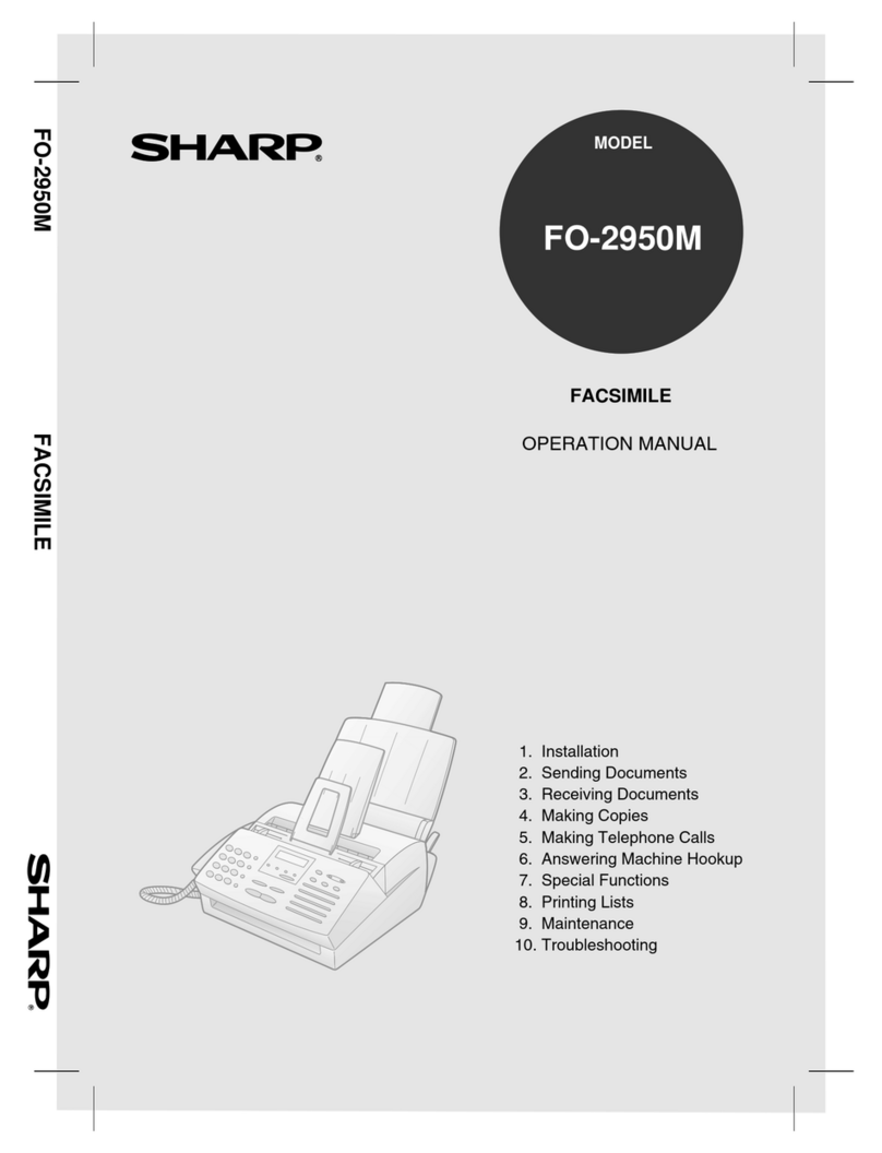
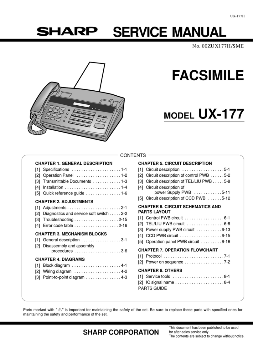
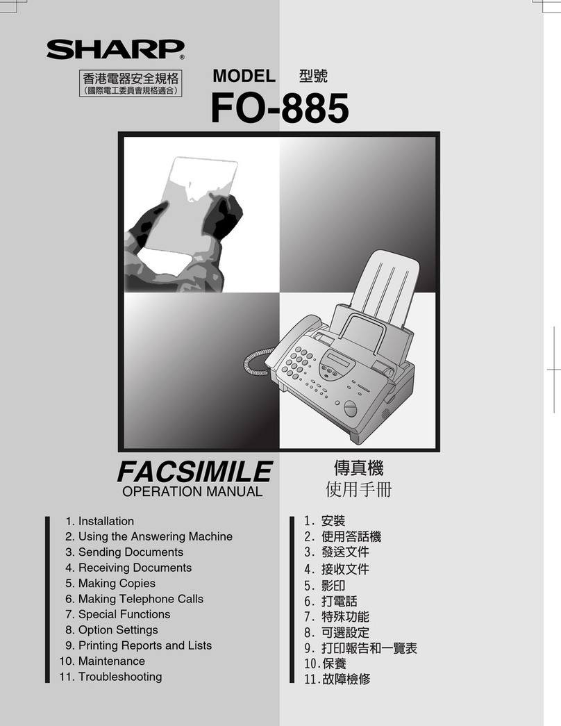
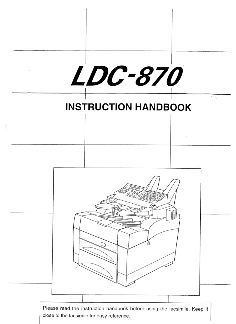
Sharp FO-145 User manual

F
SHARP SERVICEMANUAL
CODE: OOZF0145NSME
FACSIMILE
MODEL FO-I 45
/- CONTENTS \
CHAPTER 1. GENERAL DESCRIPTION
[1]Specifications .....................1-1
[2] Operation Panel . . . . . . . . . . . . . . . . . . . .1-2
[3] Transmittable Documents ............1-3
[4] Installation ...................... ..1-4
[5] Quick reference guide ...............1-6
CHAPTER 2. ADJUSTMENTS
[1]Adjustments ...................... .2-1
[2] Diagnostics and service soft switch .. ...2-2
[3] Troubleshooting ...................2-11
[4] Errorcodetabie . . . . . . . . . . . . . . .....2-12
CHAPTER 3. MECHANISM BLOCKS
[1] General description .................3-1
[2] Disassembly and assembly
procedures . . . . . . . . . . . . . . . . . . . .3-4
CHAPTER 4. DIAGRAMS
[1] Block diagram .....................4-1
[2] Wiring diagram ....................4-2
[3] Point-to-point diagram ...............4-3
CHAPTER 5. CIRCUIT DESCRIPTION
[1] Circuit description ..................5-1
[2] Circuit description of control PWB .. ....5-2
[3] Circuit description of TEL/LIU PWB .. .5-11
[4] Circuit description of
power Supply PWB ............5-15
[5] Circuit description of CCD PWB ......5-17
CHAPTER 6. CIRCUIT SCHEMATICS AND
PARTS LAYOUT
[1]
[2]
[3]
[4]
[5]
[6]
Control PW13circuit , , , ., , , ., , , , . . . ..6-1
TEL/LIU PWB circuit ................6-7
Power supply PWB circuit ...........6-10
CCD PWB circuit ..................6-12
operation panel PWB circuit .........6-13
LCD PWB circuit . . . . . . . . . . . . . .....6-14
CHAPTER 7. OPERATION FLOWCHART
[1] Protocol ...................... ....7-1
[2] Power on sequence .................7-2
CHAPTER 8. OTHERS
[1] Service tools ..................... .8-1
[2] IC signal name .....................8-4
PARTS GUIDE
Partsmarkedwith “~“ is importantfor maintainingthe safetyof the set. Be sureto reDlacethese Dartswith.sDecified
onesfor maintaining the safety and performance of the set. -
This document has been published to be used
SHARP CORPORATION for after-sales service only.
The contents are subject to change without notice.

—CAUTION FOR BATTERY REPLACEMENT
(Danish) ADVARSEL !
Lithiumbatteri-Eksplosionsfare ved fejlagtig h~ndtering.
Udskiftning ma kun ske med batteri af samme fabrikat og type.
Lever det brugte batteri tilbage til Ieverandoren.
(English) Caution !
Danger of explosion if battery is incorrectly replaced.
Replace only with the same or equivalent type
recommended by the equipment manufacturer.
Discard used batteries according to manufacturer’s
instructions.
(Finnish) VAROITUS
Paristo voi rajaht~a, jos se on virheellisesti asennettu.
Vaihda paristo ainoastaan Iaitevalmistajan suositteiemaan
tyyppiin. Havita kaytetty paristo valmistajan ohjeiden
mukaisesti.
(French) A~ENTION
IIyadanger d’explosions’ it yarempiacement incorrect
de la batterie. Remplacer uniquement avec une batterie du
m~me type ou d’un type recommande par Ie constructeur.
Mettre au rebut Ies batteries usagees conformement aux
instmctions du fabricant.
(Swedish) VARNING
Explosionsfare vid felaktigt batteribyte.
AnvAnd samma batterityp eiler en ekvivalent
typsom rekommenderas av apparattillverkaren.
Kassera anvant batteri enligt fabrikantens
instruction.

FO-145A
—.—-—--
CHAPTER 1.GENERAL DESCRIPTION
[1]SPECIFICATIONS
Applicabletelephone line:
Compatibility:
Configuration:
Compression scheme:
Scanning method:
Resolution:
Recording system:
Display:
Reception modes:
Modem speed:
Transmission time*:
Effective recording width:
Input document size:
Public switched telephone network
ITU-T (CCl~) G3 mode
Half-duplex, desktop transceiver
Modified Huffman and Sharp special
mode
Flat-bed, solid-state CCD
Horizontal:
8lines/mm
Vertical:
Standard —3.85 lines/mm
Fine/Haiftone —7.7 lines/mm
Thermal recording
7x5dots, 1line by 16-digit display
Auto/Manual/Answering machine
9600 bps with automatic fallback to
7200, 4800, or 2400 bps
Approx. 15 seconds
(Sharp special mode)
210 mm, max.
Automatic feeding:
Width —148 to 216 mm
Length —128 to 297 mm
Manual feeding:
Width —148 to 216 mm
Length —128 to 1000 mm
Effective scanning width: 210 mm, max.
Automatic document feeder: 18 sheetsmax.
Halftone (gray scale): 32 levels
Contrast control: Automatic/Darkselectable
Copy function: Standard
Telephone function: Standard
(cannotbe used if power fails)
Power requirements: 230–240 VAC, 50 tiz
Operating temperature: 5to 35°C
Power consumption: Stand-by: 7W
Transmission: 15 W
Reception: 22 W
copy: 25 W
maximum: 120 W
Dimensions: Width: 353 mm
Depth: 259 mm
Height: 122 mm
Weight: Approx. 3.7 kg
xBased on ITU-T (CCllT) Test Chart #l at standard resolution in
Sharp special mode, excluding time for protocol signals (i.e.,
ITU-T phase Ctime only).
As apart of our policy of continuous improvement, SHARP resewes the right to make design and specification changes for procduct
improvement without prior notice. The performance specifications figures indicated are nominal values of production units. There may be some
deviation from these values in individual units.
1–1

FO-145A
[2] Operation Panel
Liquid crystal display RESOLUTION key
This displays various Press this key to adjust the
messages during operation resolution and contrast
before sending or copying FUNCTION key
and programming.
\
Press this key to select
adocument.
SPEED DIAL key various special functions.
Press this key to dial a
2-digit. Speed Dial number.
\ /
REDIAL key Reception mode key
Press this key to select
Press this key to the mode of reception.
automatically redial the
last number dialed. T\’ ‘‘“ /
RE-NMOOE
K4MJAL AUTO
RESOL~NFUNCllOh
00 ‘O”
o
1
0
4
0
7
0
*
o
2
0
5
0
8
0
0
\
SPEEDDIAL
o\o
3REDIAL
@o HOLD
@o
/7
PEAKER
o
#
I01 02 03 M05 I
1(
iII I )
106 07 08 09 10
III
IIi)
I
SOP
START
COPY
oD\
D@
I
‘::::::::fthesekeysl
Numeric keys
Use these keys to dial
numbers and enter
numbers and letters
during number/name
storing procedures.
HOLD key /
Press this key to put
the other party on hold
during atelephone
conversation.
\
STOP key
Press this key to stop
operations before
they are completed.
.
to dial afax or voice START key
number automatically. Press this key to send or
(Note that you must receive adocument.
attach the Rapid key
labels.) COPY key
SPEAKER key Press this key to make
Press this key to dial aacopy of adocument.
number without picking
up the handset.
1–2

[3] Transmittable Documents
1.Document Sizes
Normal size Width \148-216 mm
Length ‘128-297 mm
----
n.-
----
-----
----
-----
----
..-
-----
-----
---
..
6zrnf12’7:a
-1-
1000mm
148mm 216mm 2f6mm
[Normalsize] ISpeciaisize]
xx Use document carrier sheet for smaller documents.
*With special sizes, only one sheet can be fed into the machine at
atime. lnsefl next page into feeder as current page is being
scanned.
2. Paper Thickness &Weight
~Thickness !0.06-0. ?2 mm
IADF 10 ;
~h
iseets Iweigh!i52–104g/m2
Normal size I~(14-281bs)
I~Thickness ~0.06-0.09 mm
~ADF 18 iI52-74.3g/mz
~sheets Weight ;~14 ~(),b~)
I-.
ISpecial size ‘Thickness ~0.12-U.20 mm
Weiqht 152-157 a/m2
3. Document Types
e
●
●
Normal paper
Documents handwritten in pencil (No. 2lead or softer), fountain
pen, ball-point pen, or felt-tipped pen can be transmitted.
Documents of normal contrast duplicated by acopying machine
can also be transmitted.
Diazo copy (blue print)
Diazo copy documents of anormal contrast maybe transmitted.
Carbon copy
Acarbon copy may be transmitted if its contrast is normal.
4. Cautions on Transmitting Documents
Documents written in yellow, greenish yellow, or light blue ink
cannot be transmitted.
Ink. glue, and correcting fluid on documents must be dry before the
documents can be transmitted.
All clips, staples and pins must be removed from documents be-
fore transmission.
Patched (taped) documents should be copied first on a copier and
then the copies used for transmission.
All documents should be fanned before insertion into the feeder to
prevent possible double feeds.
FO-145A
~.Automatic Document Feeder Capacity
Number of pages that can be placed into the feeder at anytime is as
follows:
Normal size: max. ADF 18 sheets
Special size: single sheet only (manual feed)
NOTES: “
●
When you need to send or copy more pages than the
feeder limit, place additional pages in feeder when last
page in feeder is being scanned.
Place additional pages carefully and gently in feeder.
If force is used, double-feeding or adocument jam may
result.
6. Readable Width &Length
The readable width and length of adocument are slightly smaller than
the actual document size.
Note that characters or graphics outside the effective document scan-
ning range will not be read.
●Readable width
210 mm, max.
IA
Readable width
●Readable length
This is the length of the document sent minus 4,mmfrom the top and
bottom edges.
-----------------
“~4mm
Readable length
I.................{+ Qmm
1 –3

FO-145A
7. Use of Document Carrier Sheet
Adocument carrier sheet must be used for the following documents.
●
e
●
Those with tears.
Those smaller than size 148 mm (W) x128 mm (L).
Carbon-backed documents
Makeprintstraight
acrosspaper
E.G.
Placethe document
carrierinthe document
feederwiththe clearfilm
sidedown
NOTE: To transmit acarbon-backed document, insert awhite sheet
of paper between the carbon back of the document and the
document carrier.
●Those containing an easily separable writing substance (e.g., trac-
ing paper written on with asoft, heavy lead pencil).
NOTES: ●When using the document carrier, carefully read the in-
structions written on the back.
sIf the document carrier is dirty, clean it with asoft, moist
cloth, and then dry it before using for transmission.
●Do not place more than one document in the carrier at a
time.
[4] installation
1.Site selection
Take the following points into consideration when selecting asite for
this model.
ENVIRONMENT
●
●
●
●
●
The machine must be installed on a level surface.
Keep the machine away from air conditioners, heaters, direct sun-
light, and dust.
Provide easy access to the front, back, and sides of the machine.
in particular, keep the area in front of the machine clear, or the
original document may jam as it comes out after scanning.
The temperature should be between 5° and 35°C.
The humidity should be between 30Y0and 859L (without conden-
sation).
ELECTRICITY
230-240V,50Hz, grounded AC outlet is required.
Caution!
●
●
Connection to apower source other than that specified will cause
damage to the equipment and is not covered under the warranty.
If your area experiences ahigh incidence of lightning or power
surges, we recommend that you install asurge protector for the
power and telephone lines. Surge protectors can be purchased at
most telephone specialty stores.
If the machine is moved from acold to awarm place...
If the machine is moved from acold to awarm place, it is possible
that the reading glass may fog up, preventing proper scanning of
documents for transmission. To remove the fog, turn on the power
and wait approximately 2hours before using the machine.
Assembly and connections
Connect the handset cord to the handset and the machine as
shown.
●The ends of the hand set cord are identical, so they will go into
either jack.
Piace the handset on the handset rest,
Plug the power lead into a230-240 V, 50 Hz,
AC outlet.
●The fax does not have apower onioff switch.
turned on and off by simply plugging in or
power lead.
grounded (3-prong)
so the power is
unplugging the
1 –4

@The SPEAKER/RINGER VOLUME switch controls the volume of
the speaker and the ringer. Adjust it from high (H) to low (L) as
desired.
/c
SPEAKE~lNGER
VOLUME
H-L
m
@Insert the small modular plug which terminates the F080T? adap-
tor line cord into the socket on the back of the fax marked “TEL.
LINE”. Plug the F080TP adaptor into the telephone socket on the
wall.
●Be sure to plug the line cord into the TEL. LINE socket on the
fax. Do not plug it into the TEL. SET socket.
●Your fax is designed to operate on a tone dial (DMTF) line only.
4.
0
@
ForNewZealand
@Attach the original document support.
●Insert the tabs of each into the holes at the rear of the fax as
shown.
Oriqinaldocument
@
/
FO-145.\
Loading the recording paper
Pull the cover release on the right side of the fax ‘orward, anG
open the cover.
*The fax will beep.
Remove the packing paper from the Rapercompartment.
Cover reiease
Unwrap the roll of fax paper and insert it in the compartment.
●Make sure the hubs on each side of the compartment fit into
the ends of the roll. The hub on the left side is ,mounted on a
spring to allow for insertion.
●Important: The roll must be placed so that the !eading edge of
the paper feeds out from over the top of the roll. (The paper is
only coated on one side for printing. if the roll is placed upside
down, the paper will come out biank after printinq.)
Note:
u
The paper roll provided is only asample roil which is ap-
proximately 49 ft. (15 m) long. The FO-145 uses astan-
dard 98.4 ft. (30 m) roll.
THERMAL PAPER (98.4ti. roll): FO-20PRW
@Pass the leading edge of the paper through the received docu-
ment outlet at the rear of the fax.
outlet
Close the cover by pushing down gently on the center, and then
press the START key. Ashort length of the fax paper will feed out.
Grasp the paper by the edge and pull upward to tear it off.
START
COPY
Om
DA
1–5

dI
m
.———
~5JQuick reference guide
Use this guide as aconvenient reminder for operating the machine after you have read the
detailed instructions for eachprocedure in the manual.
Note: ~-----__-. ...
11
●Steps which are optional are enclosed in adotted frame: [I
I_----- _---- -.;
Transmitting documents
NormalDialing Load ,------- Lifthandset
document+[‘Hwl +P,,,, :jEAKER +::::;:;:y.)
--------1 START
~Waitfor
c1
+@+Hangup
receptiontone
Direct Keypad START
,-------
Dialing Load !R~~UTlON~Dial(press
document c1
+ ~ O~+ numerickeys)+@
--------1
Rapid Key Dialing Load ,-------
document~[‘=m~ ~~;;ss Rapid
--------
Speed Dialing START
,-------
Load EnterSpeedDial
document_{B=M; ~SPE~DIAL
+number(press2+u@
--------1 numerickeys)
Redialing START
l_oad ,-------
0
document+ ~‘=wj +‘~m +~~~;;;ntone +@
--------
Making voice calls
NormalDialing Lifthandset Dial(press Lifthandsetifyou
press~LEAKER+numerickeys) +pressedSPEAKER
Rapid Key Dialing Lifthandset ~PressRapid ~Lifthandsetifyou
press~~EAKER key pressedSPEAKER
—
Speed Dialing Lifthandset
press~\ EAKER+“’5”” +
EnterSpeedDialnumber~Lifthandsetifyou
(press2numerickeys) pressSPEAKER
.Redialing Lifthandset ~Lifthandsetifyou
press;LEAKER +‘8L PressSPEAKER
Operations using the FUNCTION key
The following chart shows the layout of the functions and settings accessed by pressing the
FUNCTION key. First press the FUNCTION key, the appropriate unmeric key as shown, and ~
then “#” or” x’ l~ntilthe desired item appeares. z
Instructions for making each setting appear in the display. If you have any difficulty, refer to the $——
detailed instructions on the page shown below the setting.
FUNCTION
T1
m
+
4
m
Space
Answerin
dListingMode EntryMode OptionSettings
Machine ode
TAD Telephone Fax/TelNumbersFineResolution
Connected NumberList forAutoDialling Priority
QuietDetect fi~~onsSetting ~~;eN;~ber and NumberofRings
Time inAutoAnswer
Mode
FaxRecetion OwnTelephone
WhenTABNumberList
Fails
DateandTime
Set
Lettersandnumbers
Toenteraletterornumber,press
theappropriatekeyrepeatedlyuntil
thedesirednumber/letterappears
inthedisDlav(thenumberappears
. .
Pressthiskeytwiceto first,thenthelettersintheorder
enteraspace. shownabovethekey).
4RingsManual
Answer
AutoFax/Phone
Changeover
Telephone/Fax
RemoteNumber
““+
“7
HOLD
SPEAKER
o-------
-----
I
Symbols
Presseitherkeyrepeatedlyuntil
thedesiredsymbolappears
Delete
RemoteReception
Select
Transaction
ReportPrintSelect
PseudoRinging
Duration
RingerON/OFF
PaperSave
TimeSave
Pressthiskeytodeletethe
lettermarkedbythecursor(if
thecursoristotherightofthe
lastletterentered,itwill
backspaceanddeletethelast
letter).
Shift
Pressthiskeyoncetochange
case(pressitagaintochange
back).
Cursor left
Pressthiskeytomovethe
cursortotheleft.
Cursorright
Pressthiskeytomovethe
cursortotheright

CHAPTER 2. ADJUSTMENTS
[1] Adjustments
Adjustments of output voltage (FACTORY ONLY)
Output voltage settings
/
rvul MJ2
CNPSD CNSP
❑
n
D
VR1
0
r
Power Supply
uCNPW
❑CNLED
CNLIU
CNPC Dq
-
-
-w
2
3
4
5
6
7
8
7CNCUT mnu ‘
-00 c~PN CMNTCNPLG
CNCCD ‘F: ,...
$.-J
F2
CNLIU
2
\a
IFi i
a
a
IFi i
a
F
IF F
(1) Volume switch setting
(SPEAKER/RINGER
VOLUME \
2–1

FO-145A
[2] Diagnostics and service
1.Operating procedure
(1)
Entering the diagnostic mode
sofi switch
+❑,andthe following display will appear.
[ROM Ver. FSFOX ~After 2see: IDIAG MODE[
Then press the m\ key. Select the desired item with the ❑key or the ❑key or select with the rapid key. Enter the mode with the START
key.
(Diagespecifications)
If the dial mode cannot be set,
forming the following operation.
2. Diagnostic items
Softswitchsettingmode ~STARTl
ROM&RAMcheckmode-1
Agingmode m
Panelcheckmode m
Checkpatternmode m
Productcheckmode m
Signalsendmode m
Memoryclearmode m
1E
15
14
13
12
11
10
repeat the dial mode operation, per-
START STOP
KEY KEY
~‘m+“PowerON”
1
Memoryclear
(Workareaonly)
mAutofeedermode
mAllblackcopy
mCopytestmode
EEtltrycja~arcvrnode
mEntrydatasend
m] Signaldetectrnode
mccDadjustmode
ITEM ~RAPID ‘
INo. \kev IContents Function
I1‘01 ISoft switch setting mode IDisplay soft SW contents, and changes the setting.
2;02 ~ROM& RAMcheckmode ~Checks program ROM (128KByte) and work RAM (8KB~e+2KByte),
3\03 IAging mode IPrints the check pattern at the speed of 1sheet/5 minutes. I
I4104 Ipanel check mode Displays the name of key depressed on the operation panel.
\II
15 05 ~Check patiern mode Prints 2sheets of check pattern.
r
6\06 !Product check mode ~Executes No. 6, No. 3 and No. 7continuously.
707 Signal send mode Sends modem signals sequentially.
8I
!08 ~Memory ciear mode Clears the backup memory contents to reset it to the initial state.
9~09 CCD adjust mode Used for CCD adjustment. Executes copy operation. When the STOP key is pressed, the unit goes
into the wait state, When the START key is pressed again, the unit starts operation again.
10 ~10 ~signal detect mode Detecting CNG signal, quiet and DTMF signals.
-il 11 ~Entry data send ~Sends telephone list, passcode list and option set list contents in DTMF signal.
!12 I12 Entry data rev. mode ~Receives telephone list, passcode list and option set list contents.
13 ;13 Copy test mode Checks the copy operation.
14 I14 IAll black copy Pen’ormsall-dot printing (2m). (Check thermal head operation)
I
15 I15 iAuto feeder mode ~Feeds the original documents.
2–2

FO-145A
3. Diagnostic items description
Rapid key 01: Soft switch setting mode
Used to change the soft switch settings.
The soft switch which is stored internally is set by using the keys.
The available soft switches are SW1 to SW15.
The content of soft switches is shown in page 2-5 to 2-12.
The contents are set to factory default settings.
Rapid key02: ROM &RAM check mode
ROM executes the sum check, and RAM executes the matching test.
The result will be notified with the number of short sounds of the
buzzer as well as by printing the ROM &RAM check iist.
Number of short sounds of buzzer O+No error
1+ROM error
2+RAM error
Rapid key 03: Aging mode
If any document is first present, copying will be executed sheet by
sheet. If no document is present, the check pattern will be printed
sheet by sheet. This operation will be executed at arate of one sheet
per 5minutes, and will be ended at atotal of 10 sheets.
Rapid key 04: Panel check mode
In this mode, whether each key operates properly or not is checked.
Press akey on the operation panel, and the corresponding key will be
displayed. In this mode, press the STOP key, and the list of the keys
pressed in this mode will be printed with the mode ended.
Whether ail keys are pressed in this mode or not will be judged when
the list is printed, and the result will be printed.
Dial test
When the ten-key pad is pressed during panel test, dialing is per-
formed through DTMF.
Rapid key 05: Check pattern mode
This mode is used to check the status of print head. Two sheets of
check pattern are printed. The following information of check pattern
is printed.
@Verdcal stripes(alternatewhiteandblacklines)Approx. 35 mm
@Full black Approx. 70 mm
@Full white Approx. 35 mm
Rapid key06: Product check mode
This mode is used to perform No. 4(panel check), No. 2(ROM &
RAM check) and No. 5(check pattern) continuously.
This mode set the line monitor (SW4 No. 8) and quick diag (SW6
No. 4) to “YES”, and telephone number (01-04) is entered.
You will need to perform “MEMORY CLEAR” when complete.
(Rapid) (Setting number)
01 +01
02 +02
03 +03
04 +04
Rapid key07: Signal send mode
This mode is used to send various signals to the line.
FAX signals are sent in the level set by the soft switch.
[1] No signal (CML signal turned on)
[2] 9600bps
[3] 7200bps
[4] 4800bps
[5] 2400bps
[6] 300bps (FLAG)
[7] 21OOHZ(CED)
[8] 11OOHZ(CNG)
[9] END
The signal can be checked by plugging the handset into the TEL line
connector on the rear of the machine.
Rapid key08: Memory clear mode
This mode is used to clear the backup memory and reset to the
default settings.
Rapid key09: CCD adjust mode
This mode is used to adjust the optical system. Since the copy is
function performed, set the original. To abort the copy operation,
press the STOP key. To restart press the START key. When the copy
is completed or when the STOP key is pressed in the interruption
state, exit from this mode occurs.
Rapid key 10: Signal detect mode
This mode is used to detect signals on the EXT. TEL line (CNG,
QUIET, DTMF).The results are given with the result list.
Rapid key 11: Entry data send
This mode is used to send the registered data to the remote machine
and make the remote machine copy the registered information. When
this mode is used for sending, the remote machine must be set to the
entry data receive mode (Rapid key 12).
The information to be sent is as follows.
1. Information which can be registered in the ‘FUNC” +“3” entry
mode.
(Excepting data and time)
2. Soft switch data
2-3

FO-145A
Rapid key 12: Entry data rev. mode
This mode is used to receive the registered data which is sent from
the remote machine and to register the received data in the machine.
When this mode is used to receive the information, the remote ma-
chine must be set to the entry data send mode (Rapid key 11).
After completion of reception, the telephone number list, passcode
list, option set list, and soft switch list are printed.
Caution
Unless the time mode is set, the list print is not performed, “NO
DATAmappears on the display.
Rapid key 13: Copytest mode
This mode is used to check the copy operation and picture quality.
Before using this mode, set the original. If there is no original, the
recording paper is cut.
The first page is copied in condition of FINE/AUTO the second and
the subsequent pages are copied in condition of H-TONE/DARK.
4. How to make soft switch setting
To enter the soft switch mode, make the following key entries in
sequence<
Rapid key 14: All back copy
This mode is used to check the print head.
All-dot print is executed unconditionally until 2(m) is obtained except
when any trouble occurs (recording paper has run out, recording
paper jam, thermal protect).
Rapid key 15: Auto feeder mode
In this mode, adocument is insertedanddischargedto check the
auto feed function.
After this mode is started, set adocument, and the document feed
will be automatically tested.
IPress [FUNCTION] ❑ ❑ ❑ ❑ ❑ mml
DATANo. 1 2 3456 78
SFT SW!=o0 0 0 0 0 0 01 1
J
SFT SW1=fo000000[ -
J
SFT SW1=1 0000000 ‘J
SFT SW1=1 0 0 0 0 0 0 01 .
ISFT SW1=10 0 0 0 0 0 u~ -
1
J
SFT SW2=o0 0 00 0 0 01
ISFT SW15= O0 0 0 0 0 0 Oi -
Press1- key.
Press❑key.
Press~key.
Bitl -8 areset.
PressHkeyduringsetting.
SoftSW2-SWI5are set.
.To finish the settingshalfwaybetween
SW 1andSW15, presstheSTOP key.
Inthiscase,the settingbeingdoneto
theSW No. ondisplaywillbe nullified
whilesettingsdoneto thepreceding
SW Nos. remainin effect.
IThe soft switchmodeisterminated. I
2–4
FO-145A
5. Soft switch description
●Softswitchlist
SW IDATA Soft SW setting and function Initial ~~emark<
NO. ~NO. ,ITEM 1IoIsetting
I
11 Line density choice IFine Standard io;OPTICN
i2 Reserved Io’
!‘Allways INot printed ~
Communication result printout ,Only in error Only in
1(transaction report print select) 1sending print
,
SI 3!NO. 3~O~O1~l\o oPTicN
w4NO. 4~Oi10!1Io
1Automatic switching from manual to jReception after 4rings ~No reception 10
5IOPTION
auto receive mode I !
I
6Automatic switchinq mode ITE~’FAX auto switch 1Switch to FAX oOPTICIN
7End buzzer ]NO ~YES Io
8Fax switching when answering ~‘fES iNO 1OPTiClhi
machine recording full !1
!,0
(
1300 BPS frame check time ~6sec ~3sec 1’
2Forced 4800 BPS reception ~YES iNO o
3Reserved I~o
s4CED tone-signal interval I500msec ~7~msec o
w
25Reserved Io,
)
6Digital line equalization setting ION ~OFF ]1
,
~9600BPS 7200BPS \4800BPS ~2400BPS I
I1
7Modem speed NO. 7\1 1 IoioI1
8NO. 8~oI I ~I / o~o
~Maximum copy, transmission, INo limit
1’ Copy/transmission: 1m~
reception page length ,Reception: 1.5m [o
I2\Footer print INO 10
s3Sender’s phone number registration ~Change inhibited IChange allowed (o
w4CSI transmission ~Not transmitted ITransmitted
30
I
5Quiet Detect Start Time \Binary input 8421 0
I
6
7I
,
I
no. 5678
0101
11
1’
!o,
8IFactory setting: 5sec 11
I1\Reserved !I/0
/2/Dial pause (see/pause) I2sec ,0
I3IReserved II10
s4DIS receive acknowledgment during Twice NSFsignal: Once
wG3 transmission DIS signal: Twice 0i
45Non-modulated carrier detection for YES NO 0’
V29 modem
6EOL (End of Line) detect timer 25 sec 5sec o
7Protocol monitor YES NO o
8Line monitor YES NO o
1Signal transmission level Binary input 8421 1
2no. 1234 1
31110 1
s4Factory setting: -14dBm (Modem output)
w5Sendets information transmit ~NO
5IYES I ; I
6H2 mode NO YES Io~
Reading slice (Binary) Factory Light Dark Lighter ~I
setting II I
7NO. 70101’01
8!NO. 8001 1 o~
2–5

FO-145A t
Sw DATA Soft SW setting and function Initial I
NO. NO. ,ITEM Remarks
1Io1setting
IIReading slice (halftone) Factory ~Light Dark Lighter 1
1, INO.10Illo 1IoI
21 NO.2001 1 0
,3ICharacter detection sensitivity setting Strong IWeak o
in halftone mode
sI I
w4Into DIAG mode by SPEED key YES ~NO o
6 5 Communication error treatment Not communication error \Communication error o
I(reception) in RTN sending II
DTMF detection time 50ms i80ms !1OOms 120ms
6NO. 6001 1 0
I
7NO. 701 0 1 0
8Protection of remote reception YES NO oOPTION
(5, %,* )detect
1Autodial mode 3 sec ‘Osec 11
Delaytimer of before-line connect
Autodial mode 1.7 sec 3 sec 3.6 sec 3.6 sec
2Delaytimer of after-line connect NO. 20 0 1
s10
w3NO. 30 1 0 1
74Reserved 1:
!1
I,I
I5jCNG transmission INO IYES 101
6Remote reception Compatible ~Not Compatible 1
(corresponding to TEL made by GE)
7Auto gain control (MODEM) Enable \Disable 1
8Reserved 1
I
1Recall interval Binary input 8421 ~: I
2no. 1234 II
s30101 1.
w4Factory setting: 5minutes
81
5Recall times Binary input 8421 Oi
I6no. 5678
70010
8I ;
Factory setting: Twice o
1Number of rings for auto answer Binary input 8421 0OPTION
2mode no. 1234
I
s3, 0001 I“l
10’
w4! Factory setting: 1times
911
5Remote operation code figures by Binary input 8421 0OPTION
6external TEL (O-9) no, 5678 1
i7 II0101 II
I01
II
1: Factory setting: 5
Ringer switch OFF /ON [: OPTION
2Busy tone detection continuous 10 sec !
;5sec In
1Isound detect time I
Number of busy tone detection pulse [
2pulses [4pulses 6pulses
s10 pulses \
I
WI 3NO. 3010 110
10 \4NO. 401011
5Ci off detection timer 350 msec I700 msec
(Distinctive ring setting off only) lo
6Reserved o
71Reserved
8;Reserved 1:
2–6

SW
tie.
s
w
11
s
w
12
s
w
13
s
w
14
s
w
15
DATA
NO.
1
2
3
4
5
6
7
8
1
2
3
4
5
6
7
8
1
2
3
4
5
6
7
8
1
2
3
4
5
6
7
8
1
2
3
4
5
6
7
8
FO-145A
SoftSW setting and function ~Initiai ~~emar~~
ITEM 10\setting
Busy tone detection I350ms 150ms Io;
ON/OFF time (Lower limit) I I
I
Busy tone detection 650ms 900ms
ON/OFF time (Upper limit) ~0~
TAD connected IYES NO o0PTION
Busy tone detection intermittent \NO YES I0,
sound detection I
1
Number of CNG signal detection in I1 2 3 1 4 4
T.A.D. mode. 1
NO. 5 0 01I11 0
NO. 6 0 10 1 1 ‘1
Reserved o:
I
Reserved oI-
Reserved i0~
Reserved I\o;
Reserved 1 0 1
Reserved Io’ .....
Reserved o
I
Reserved Io
Resewed I
Io
Reserved o
Reserved Io~—.
Reserved o~
),
Reserved IIIo
Quiet detect time Binary input 16 8 4 2 1 i:~
*p~~~’J
no. 45678
00100 I
Factory setting: 4sec I ; i
Pseudo ringing time at Phone/Fax I15s 30s 60s 120s ‘
automatic switching mode ,
jNO. 110 1 0 1Io
NO. 20 0 1 1‘ i 0
Eauaiization freeze control ION IOFF 10 !
Equalization freeze 7200BPS only INO IYES I11
I
Pseudo ringing sound volume –lOdB ~–15dB -5dB IOdB !I
(TElfFAX selection) Normal Lower Louder Loud ~
I
NO. 50 1 0110
NO. 6 0 0 1 1 0~
Reserved o
Reserved o
Section time of quiet detection 30sec 40sec 50sec 60sec
NO. 1001 1 0
NO. 201 0 1 1
Resewed oI
Reserved o
Post answer tone Disable Enable o,
Reserved
Reserved 1: I
Reserved o
2–7

FO-145A
@Soft switch functional description
SWI No. 1Line density choice
Used to set the transmission mode which is automatically selected
when the Resolution key is not pressed. In the copy mode, however,
the fine mode is automatically selected unless the Resolution key is
manually set to another mode.
SWI No. 2Reserved
Set to “O”.
SW1 No. 3, No. 4Communication result printout
(transaction report Print select)
It is possible to obtain transaction results after each communication.
Normally, the switch is set (No. 3:0, No. 4:0) so that the transaction
report is produced only when acommunication error is encountered.
if No. 3was set to 1 and No. 4to O,the transaction report will be
produced every time acommunication is done, even if the communi-
cation was successful.
Setting No. 3to 1 and No. 4to 1will disable this function. No transac-
tion repofi printed.
No. 3:0 No. 4:1=TX ONLY Report Print
SW1 No. 5Automatic switching from manual to auto receive.
mode
This soft switch is used to select whether the machine should switch
to the auto receive mode after 4rings in the manual receive mode or
remain in the manual mode. When the soft switch is set to “1”, the
machine operates in the same way as SW9 No. 1-No. 4.
SW1 No. 6Automatic switching mode
This soft switch is used to set the auto tel/fax select mode or to set
tne normal fax mode.
SW1 No. 7End buzzer
Setting this bit to “1” will disable the end buzzer (including the error
buzzer/on-nook buzzer).
SW1 No. 8Fax switching when answering recording full
Used to disable or ~nable the function of OFF-HOOK hold.
[f the answering machine’s memory (tape) is full and there is no
response, the machine automatically switches to Fax reception.
The OFF HOOK hold time (Answering machine operating time) is set
by normal operation.
SW2 No. 1300 BPS frame check time
Communication command wait time setting (Used by technical engi-
neers. For the market, fixed to 6S.)Default setting: 6S
SW2 No. 2Forced 4800 BPS reception
When line conditions warrant that receptions take place at 4800 BPS
repeatedly. It may improve the success of receptions by starting at
4800 BPS. This improves the receiving document quality and reduces
handshake time due to fallback during training.
SW2 No. 3Reserved
Set to “O”.
SW2 No. 4CED tone-signal interval
For international communication, the 21OOHZCED tone may act as
an echo suppression switch, causing acommunication problem.
Though this soft switch is normally set to “O”,it should be set to “1” so
as to change the timer between the CED tone and DIS signal from
75ms to 500ms to eliminate the communication problem caused by
echo.
“O”set: T=75ms
“1” set: T=500ms
TX RX
SW2 No. 6Digital line equalization setting
Line equalization is to be set according to the line characteristics.
Setting should be made according to the distance between the tele-
phone and the telephone company central switching station.
SW2 Not7, No. 8Modem speed
Used to determine the initial modem speed. The default is 9600bps. It
may be necessary to program it to aslower speed when frequent iine
fallback is encountered, in order to save the time required for fallback
procedure.
SW3 No. 1Maximum copy, transmission, reception page length
Used to set the maximum page length.
To avoid possible paper jam, the page length is normaliy iimited to 1
meter for copy or transmission, and 1.5 meters for reception.
it is possibie to set it to “No limit” to transmit along document, such
as acomputer print form, etc. (in this case, the receiver must aiso be
set to no limit.)
SW3 No. 2Footer print
When set to “1”, the date of reception, the sender machine No., and
the page No. are automatically recorded at the end of reception.
SW3 No. 3Sender’s phone number registration
Used to make achoice of whether the registered sender’s phone
number can be changed or not. if the switch is set to “1”, new regis-
tration of the sender’s phone number is disabied to prevent accidental
wrong input.
SW3 No. 4CSI transmission
(CSi TRANSMISSION) is aswitch to set whether the machine sends
or does not send the signal (CSi signai) informing its own telephone
No. to the remote fax machine when information is received. When
“nonsending” is set, the teiephone No. is not output on the remote
transmitting machine if the remote transmitting machine has the func-
tion to dispiay or print the teiephone No. of receiving machine, using
this CSI signai.
SW3 No. 5- No. 8Quiet detect start time
Inserts apause before commencing quiet detection.
SW4 No. 1Reserved
Set to “O”.
SW4 No. 2Dialing pause
Pauses can be inserted between telephone numbers of direct dial
connection. Seiection of 4sec or 2sec pause is availabie.
SW4 No. 3Reserved
Set to “O”.
SW4 No, 4DIS receive acknowledgment during G3 transmission
Used to make achoice of whether reception of DiS (NSF) is
acknowledged after receiving two DiSs (NSFS) or receiving one DiS
(two NSFS).
it may be Usefuifor overseas communication to avoid an echo sup-
pression probiem, if set to 1.
SW4 No. 5Non-modulated carrier detection for V29 modem
Though transmission of anon-moduiated carrier is not required for
transmission by the V29 modem according to the ITU-T (CCi~)
Recommendation, it may be permitted to asend non-moduiated car-
rier before the image signal to avoid an echo suppression probiem.
it may be usefui for overseas communication to avoid an echo sup-
pression probiem, if set to 1,
SW4 No. 6EOL (End Of Line) detect timer
Used to make achoice of whether to use the 25-second or 5-second
timer for detection of EOL.
This is effective to override communication faiiures with some
facsimiie modeis that have ionger EOL detection.
SW2 No. 5Reserved
Set to “O”.
2–8

FO-145A
SW4 No. 7Protocol monitor
Normallyset to “O”.If set to “1”,communicationcan be checked, in
case of troubles, without using aG3 tester or other tools.
When communication FSK data transmission or reception is made,
the data is taken into the buffer. When communication is finished, the
data is analyzed and printed out. When data is received with the line
monitor (SW4-NO.8) set to “1”. the reception Ieve! is also printed out.
SW4 No. 8Line monitor
Normally set to “O”.If set to “l”, the transmission speed and the
reception level are displayed on the LCD. Used for line tests.
SW5 No. 1- No. 4Signal transmission level
Used to control the signal transmission level in the range of -OdB to
-1 5dB.
The factory setting isat–14dB (Modem output).
SW5 No. 5Sender’s information transmit
(SENDEI?’S INFORMATION TRANSMISSION) is aswitch to set the
function to print the content of HEADER PRINT described in the
passcode list at the front end of receiver’s original when oflginal is
sent to the remote machine.
If this switch is set to “NOD,the HEADER PRINT is not output at the
receiving machine.
SW5 No. 6H2 mode (SHARP special mode)
Used to determine reception of H2 mode (15 sec transmission mode).
When set to OFF, H2 mode reception is inhibited even thcugh the
transmitting machine has H2 mode function.
SW5 No. 7, No. 8Reading slice (binary)
Used to determine the set value of reading density in standardjfine
mode. The standard setting is “00”. (Factory setting is “00”.)
SW6 No. 1, No. 2Reading slice (halftone)
Used to determine the set value of reading density in halftone mode.
The standard setting is “00” (Factory setting is “00”).
SW6 No. 3Character detection sensitivity setting in halftone
mode
In the halftone mode, image area is separated from character area
and processed separately to eliminate unclear character transmis-
sion. This switch is used to change the criteria of judgement of sepa-
ration. When “Strong” (=1)is selected, more area is judged as char-
acter area, providing clearer characters. On the contrary, however,
edges of image area may be emphasized.
It is advisable to restrict the use of this function only when clear
characters must be transmitted, and to use the function of ‘Weak”
(=0) for general use.
SW6 No. 4Into DIAG mode by SPEED key
Abit which is used in the productionprocess only. When the
“SPEED” key is pressed, the switch is changed from the stand-by
state to the DIAG mode.
SW6 No. 5Communication error treatment (reception) in RTN
sending
Used to detemine communication error treatment when RTN is sent
by occurrence of areceived image error in G3 reception. When it is
set to “1”, communication error isjudged as no error.
SW6 No. 6, No. 7DTMF detection time
Used to set detection time of DTMF (Dual Tone Multi Frequency)
used in remote reception (5,M, x).
The longer the detection time is, the less the error detections are
caused by noises.
SW6 No. 8Remote reception (5,*, ~)detect
Used to set the function of remote reception (5, x,x). When set to
“1”, the remote reception function is disabled.
SW7 No. 1Auto dial mode Delay timer of before-line connect
Delay time between the dial key input and line connection under the
auto dial mode.RAPIDO1 CMLRELAYON
SW7 No. 2, No. 3Auto dial mode Delay timer of after-line connect
Delay time between the line connection and dial data output under
the auto dial mode.
+DIALDATA—
RAPIDO1 CMLRELAYGN
vvI-Inn
SW7 No. 4Reserved
Set to “O”.
SW7 No. 5CNG transmission
When set to ‘(0”,this model allows CNG transmission by pressing the
start key in the key pad dialing mode. When set to”1”, CNG transmis-
sion in the key pad dialing mode cannot be performed. In either case
CNG transmission can be performed in the auto dial mode.
SW7 No. 6Remote reception
(Corresponding to TEL made by GE) P.B.X.
“1”:Compatible with TEL made by GE
“O”:Not compatible
●When sending (5, *, x)for remote reception with aGE manu-
factured telephone, remote reception may not take place because
of special specifications in their DTMF.
To overcome this, asoft SW is provided to change the mcc!em
setting to allow for remote reception.
0If this soft SW is set to “1”, other telephone sets may be adversely
affected.
SW7 No. 7Auto gain control (MODEM)
When this mode is enabled, if the reception signal level is undsr
31dBm. The modem itself controls the signal gain automatically.
SW7 No. 8Reserved
Set to “O”.
SW8 No. 1- No. 4Recall interval
Choice is made for aredial interval for speed and rapid dial calls. Use
abinary number to program this. If set to Oaccidentally, 1IWIIIbe
assumed. If anumber above 5was entered, it will be set to 5. in this
case, it has to be corrected.
SW8 No. 5- No. 8Recall times
Choice is made as to how many redials should be made. Use a
binary number to program it. If set to Oor 1by accident, the redlal
number will be set to 2. If anumber above 9was entered, it will be
set to 9.
SW9 No. 1- No. 4Number of rings for auto answer mode
When the machine is set in the auto receive mode, the number of
rings before answering can be selected. It may be set from one tc
ninerings using abinaty number. Since the facsimile telephone could
beused as an ordinary telephone if the handset is taken off the hook,
itshould be programmed to the user’s choice. If the soft switch was
set to 1, direct connection is made to the facsimile. If afacsimile
calling beep was heard when the handset is taken off the hook, press
theSTART key and put the handset on the hook to have the facsimi!e
start receiving. if it was set to Oaccidentally, receive ring is set tG1. If
it was above 9, receive rings are set to 9.
NOTE: If the machine is set to answer after alarge number of rings,
it may not be able to receive faxes successfully. If you have
difficulty receiving faxes, reduce the number of rings to a
maximum of 4.
SW9 No.5 -No.8 Remote operation code figures by external TEL
Remote operation codes can be changed from Othrough 9. If set to
greater than 9, it defaults to 9. The “x“is not changed and the new
function becomes, number programmed plus x.
Ex-7 *+(Default: “5” “%“ “ %“.)
SWIO No. 1: Ringer switch
If this switch is set to “OFF”, the ringer of fax does not ring when a
call from aparty is received.
~D’AL’’N’—
0: Osec
1:3sec 2–9

FO-145A
SWIO No. 2Busy tone detection continuous sound detect time
Selectsdetectionof the continuoussoundof 440Hz (SWI 1No. 8) for
10 sec or 5sec.
SW1ONo. 3, No. 4Number of busy tone detection pulses
Used to set detection of busy tone continuous sounds.
SWIO No. 5Ci off detection timer
(Distinctive ring setting off only)
Sets the minimum time period of Cl signal interruption which affords
to be judged as aCl OFF section.
~A~ +B+
~l—1~
400msec 2000msec
(i’J a
SFTSW1O-5 =0:700 msec (Cl interruption >700 msec: Judged as
aCl OFF section)
The section @is not judged as aCl OFF section, the Cl signal A
is counted as one signal.
The section @is judged as ac1 OFF section, the c1 si9nal BiS
considered as the second signal.
SHSW1O-5 =1:350 msec (Cl interruption >350 msec: Judged as
aCl OFF section)
The section @is judged as aCl
IScounted as two signals.
The section @is judged as aCl
is considered as the third signal.
SWIO No. 6- No. 8Reserved
Set to “O”.
OFFsection, and the Cl signal A
OFFsection, and the Cl signal B
SWII No. 1Busy tone detection ON/OFF time (Lower limit)
The initial value of detection is set according to electric condition.
The set value is changed according to the local switch board. (Erro-
neous detection of sound is reduced.)
Normally, the upper limit is set to 900ms, and the lower limit to
150ms.
If erroneous detection is caused by sound, etc, adjust the detection
range.
The lower limit can be set in the range of 350ms to 150ms.
SWII No. 2Busy tone detection ON/OFF time (Upper limit)
Similarly to SW11 No. 1, the set value can be varied.
The upper limit can be set in the range of 650ms to 900ms.
SW12 No. 1- No. 8Reserved
Set to “O”.
SW13 No. 1- No. 3Reserved
Set to “O”.
SW13 No. 4- No. 8Quiet detect time
(Used in answering machine mode)
When an answering machine is connected, if a no sound state is
detected for acertain period of time, the machine judges it as a
transmission from afacsimile machine and automatically switches to
the Fax mode.
SW14 No. 1, No. 2Pseudo ringing time at Phone/Fax automatic
switching mode
Choise is made to as how long to rumble the dummy ringer on
TEUFAX automatic switching mode.
SW14 No. 3Equalization freeze control
This switch is used to perform reception operation by fixing the equal-
izer control of modem for the line which is always in unfavorable state
and picture cannot be received.
*Usually, the control is executed according to the state of line where
the equalizer setting is always changed.
SW14 No. 4Equalization freeze 7200BPS only
Setting which specifies SW14, No. 3control only in condition of
7200BPS modem speed.
SW14 No. 5, No. 6Pseudo-ringer sound volume (on selecting
TEMFAX)
Used to adjust sound volume of pseudo-ringer (ring back tone) gener-
ated on selecting TEUFAX. Setting can be altered.
SW14 No. 7, No. 8Reserved
Set to “O”.
SW15 No. 1, No. 2Section time of quiet detection
The switch which sets the time from the start of quiet detection func-
tion tOthe end of the function.
SW15 No. 3- No. 5Reserved
Set to “O”.
SW15 No. 6Post answer tone
This switch is used to send tones of RA (880Hz), S1(988Hz), and DO
(1046Hz) in the TEUFAX auto select mode.
SW15 No. 7, No. 8Reserved
Set to ‘O”.
ISW11 No. 11SW11 No. 2IDetection range I
o10 150ms–900ms
o 1 150ms –650ms
10350ms -900ms
11350ms -650ms
SW1l No. 3TAD CONNECTED
When connecting the answering machine to the extension telephone
jack, set to “1”.
SWI 1No. 4Busy tone detection
Line off detection YES/NO is set.
SWII No. 5, No. 6Number of
mode
Used for detection of CNG in 1-4
SW11 No. 7, No. 8Reserved
Set to “O”.
intermittent sound detection
CNG signal detection
pulses in T.A.D. mode.
in T.A.D.
2-10

FO-145.I
[3] Troubleshooting
Refer to the following actions to troubleshoot any of problems men-
tioned in 1-4.
[1]
[2]
[3]
[4]
Acommunication error occurs.
Image distortion produced.
Unable to do overseas communication.
Communication speed slow due to FALLBACK.
cIncrease the transmission level SOFT SWITCH 5-1234.
May be used in case [1] [2] [3].
●Decrease the transmission level SOFT SWITCH 5-1234.
May be used in case [3].
●Apply line equalization SO~ SWITCH 2-6.
May be used in case [1] [2] [3] [4].
●Slow down the transmission speed SOFT SWITCH 2-7. 8.
May be used in case [2] [3].
●Replace the LIU PWB.
May be used in all cases.
●Replace the control PWB.
May be used in all cases.
*If transmission problems still exist on the machine, use the folct;i-
ing format and check the related matters.
TO: An: Ref.No. :
---------------------- ------ ---------------------------------------------------------------------------------- ---——
---
cc: An: Date :
-------------------------------------------------------------------------------------- ---------------------- _-—------.—--
FM: Dept :
-------------------------------------------------------------------------------------------------------- -—-__ -----.--—
Sign :
---------------------------------- ------------------------------------------------------------------------------------
“**** Facsimile communication problem ●**** Ref.No.:
From: Mr. ----- —-------------—-— -- .-—
---
Fax Tel No.: Date:
Our customer
~
Name Tel No.
------------------------------------------------ -------------------------------------------------------
Address Fax No.
----------------------------------------------------------------------------------- ---------- —---------
~Contact person Model name
Other party !Name
1
Tel No.
------------------------------------------------------------------------------------------
Address -------------
r
Fax No.
-------------------------------------------------------------------------------------------------------
Contact person Model name
Problem mode Line: Domestic /international Model: G3 Phase: A, B, C, D.
Reception /Transmission !Automatic reception/ Manual reception
~Automatic dialing/ Manual dialing/ Others
Frequency: 0/0 IROM version:
Confirmation IPlease mark problem with an X.
item Our customer Otherparty No problem is: O.
Al A2 ;61 ~B2 ~Cl C2 ~D1 ~02 El E2
----- <----
~:~;: -:;s :m:::-]----[--- ----,---;dBatcur
Transmission level setting is (
El ➤
4E2 Transmission level ( ) dBm
Our setvice Otherparty’ssetvice Reception level ()dBm
By level meter at B1 and 62
Comment
---------------- -------------------------------------------------------------------------------------------------------
Countermeasure
●*** Please attach the G3 data and activity repod on problem. ●***
.-.
“Pleasecomplete this report before calling the “TAC” hotline if problem still occurs.
2–11

FO-145A
[4] Error code table
G3 Transmission
Code Finalreceivedsignal Error Condition (Receiver side)
oIncomplete signal frame Cannot recognize bit stream after flag
1NSF, DIS Cannot recognize DCSsignal
Cannot recognize NSS signal
2ICFR Disconnects line during reception
31~ Disconnects line by fallback
4~MCF Disconnects line during reception of multi-page
Cannot recognize NSS, DCS signal in the case of mode change
5~PIP or PIN No response in receiver side to picture signal after no response in transmitter side to receive
TALK mode request
6\RTN or RTP Cannot recognize NSS, DCS signal after transmitting RTN or RTP signal.
7iNo signal or DCN No response in receiver side or DCN signal received’
G3 Reception
ICode Final received signal Error Condition (Transmitter side)
IoIImcompiete signal frame ICannot recognize bit stream after flag
1NSS, DCS Cannot recognize CFR or ~signal
Disconnects line during transmission
2NSC. DTC Cannot recoanize NSS sianal
I3IEOP \Cannot recognize MCF, PIP, PIN, RTN, RTP signal I
4~EOM ICannot recognize MCF, PIP, PIN, RTN, RTP signal in the case of mode change
5~MPS ~Cannot recognize MCF, PIP, PIN, RTN, RTP signal in the case of multi-page
I6;PR1-Q /cannot recognize Pip, PIN signal in the case of TALK request I
I7~No signal or DCN INo response in transmitter (cannot recognize DIS signal) or DCN signal received’ I
2 – 12
Other manuals for FO-145
1
Table of contents
Other Sharp Fax Machine manuals