3
2
•
Do not touch the connector pin contacts as static
electricity may damage the internal parts of the level
converter.
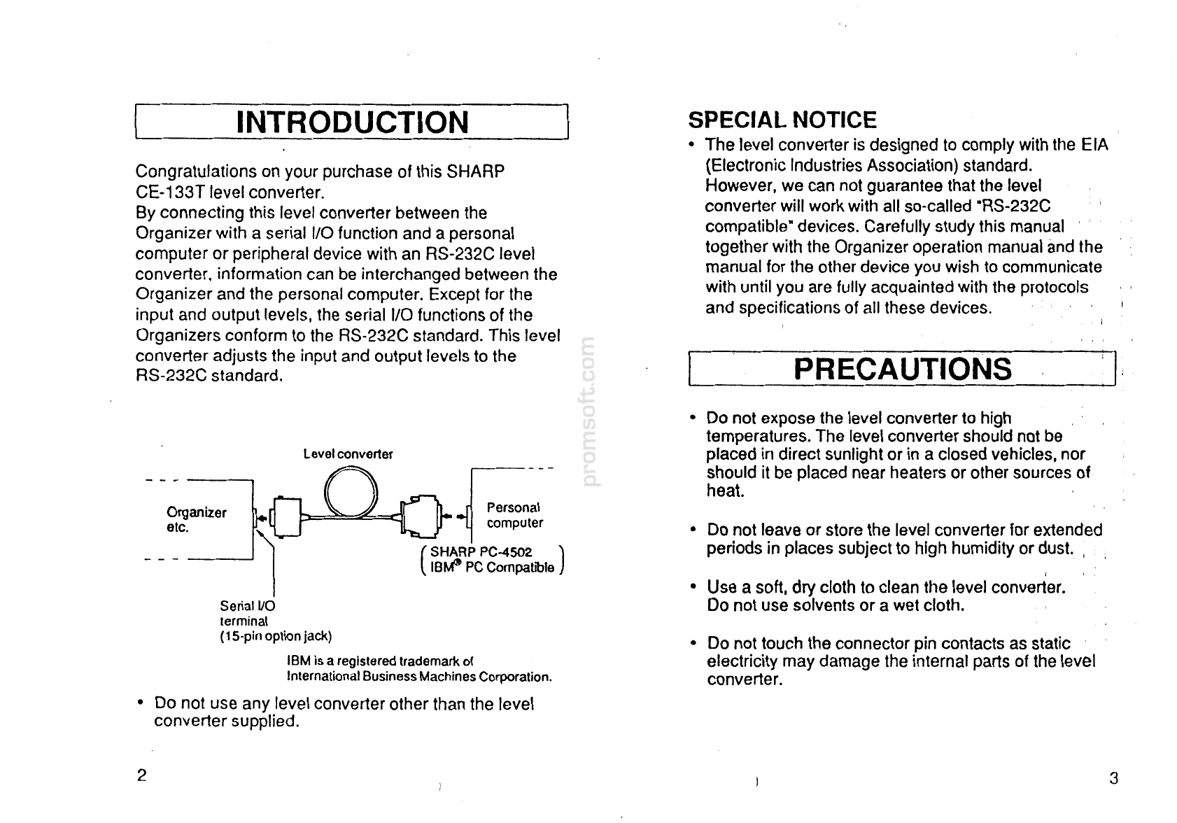
Serial
VO
terminal
(
15
-
pin option jack)
IBM is a registered trademark of
International Business Machines Corporation.
•
Do not use any level converter other than the level
converter supplied.
I
'
•
Use a soft, dry cloth to clean the level converter.
Do not use solvents or a wet cloth.
(
SHARP PC-4502
)
IBMI
PC Compallble
•
Do not leave or store the level converter for extended
periods in places subject to high humidity or dust.
,
Personal
computer
Level converter
•
Do not expose the level converter to high
.
temperatures. The level converter should not be
placed in direct sunlight or in a closed vehicles, nor
should it be placed near heaters or other sources of
heat.
PRECAUTIONS
I
,
.
Congratulations on your purchase of this SHARP
CE-133T level converter.
By connecting this level converter between the
Organizer with a serial 1/0function and a personal
computer or peripheral device with an
RS
-
232C level
converter, information can be interchanged between the
Organizer and the personal computer. Except for the
input and output levels, the serial 1/0 functions of the
Organizers conform to the RS-232C standard. This level
converter adjusts the input and output levels to the
RS-232C standard.
SPECIAL NOTICE
•
The level converter
is
designed to comply with the EIA
(Electronic Industries Association) standard.
However, we can notguarantee that the level
converter will work with all so-called "RS-232C
compatible"
devices
.
Carefully study this manual
together with the Organizer operation manual and the
manual for the other device you wish to communicate
with until you are fully acquainted with the protocols
and specifications of all these
devices
.
INTRODUCTION


