Sharp AN-LS1 User manual

Introduction Connections Setup Using the Software Appendix
MODEL AN-LS1
OPERATION MANUAL
Ethernet to RS-232C Network Converter
•Please read this operation manual carefully
to ensure correct use of the Ethernet to RS-
232C Network Converter.
•Please read this operation manual together
with the “IMPORTANT INFORMATION”
leaflet.
•Prior to installation of this product, carry
out the appropriate network settings.

2
Outstanding Features
AN-LS1 is a network converter for converting TCP/IP protocol on Ethernet to serial (RS-232C).
■AN-LS1 enables Sharp projectors with RS-232C terminals to be controlled via
Ethernet.
■Since AN-LS1 is provided with an RS-232C terminal as well as an Ethernet terminal,
control using a commercially available locally installed controller is possible as
well as via a network.
Control via network
Local control
Computer
Controller
Projector
Ethernet
LAN
In this operation manual, the illustration and the screen display are simplified for explanation,
and may differ slightly from actual display.
Accessories
Supplied Accessories
■■AC Adaptor
■■CD-ROM (Driver software and PDF operation manual)
■■IMPORTANT INFORMATION (Leaflet)
■■USA/Canada warranty card
■■International Software license (Paper)
•Microsoft and Windows are registered trademarks of Microsoft Corporation in the United States and/or other
countries.
•All other company or product names are trademarks or registered trademarks of their respective companies.

3
Introduction
Contents
Introduction
Outstanding Features ......................................................................................................................... 2
Accessories ........................................................................................................................................ 2
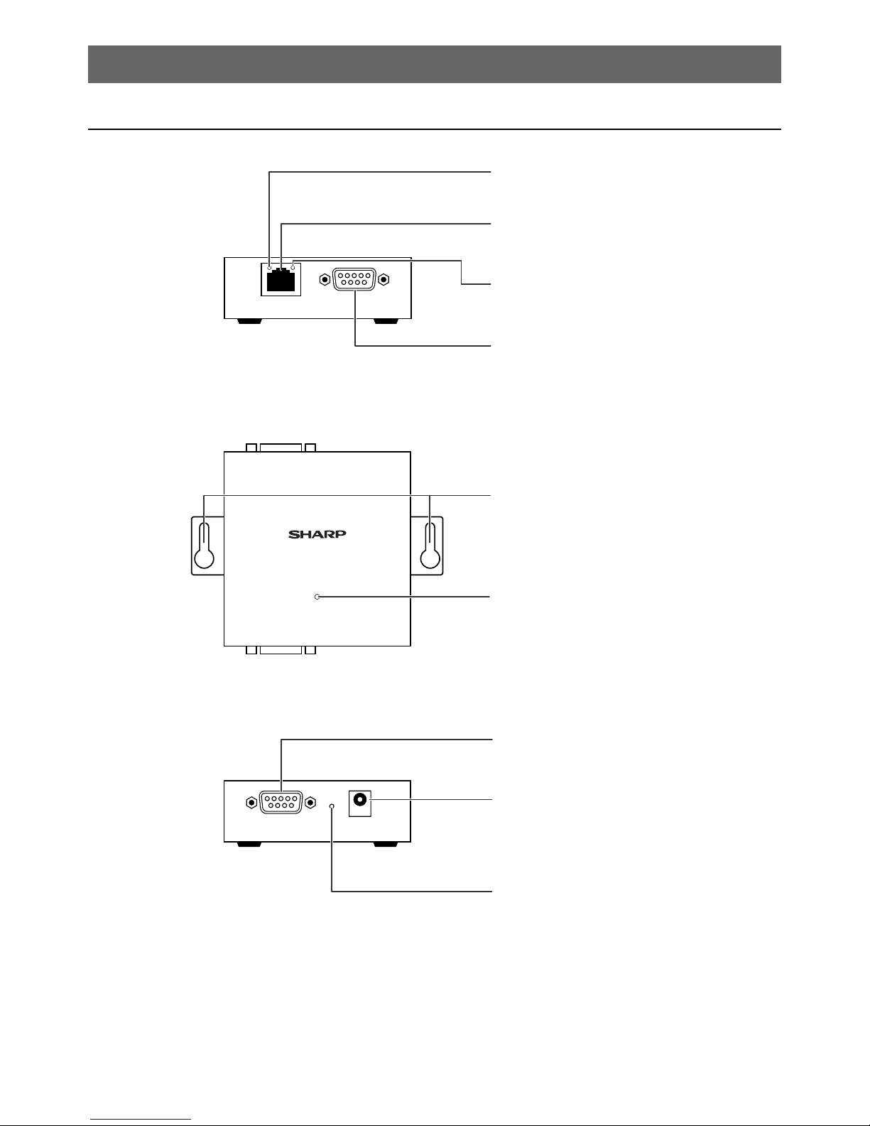
Part Names and Functions................................................................................................................. 4
Main Body ................................................................................................................................ 4
LED Indicators.......................................................................................................................... 5
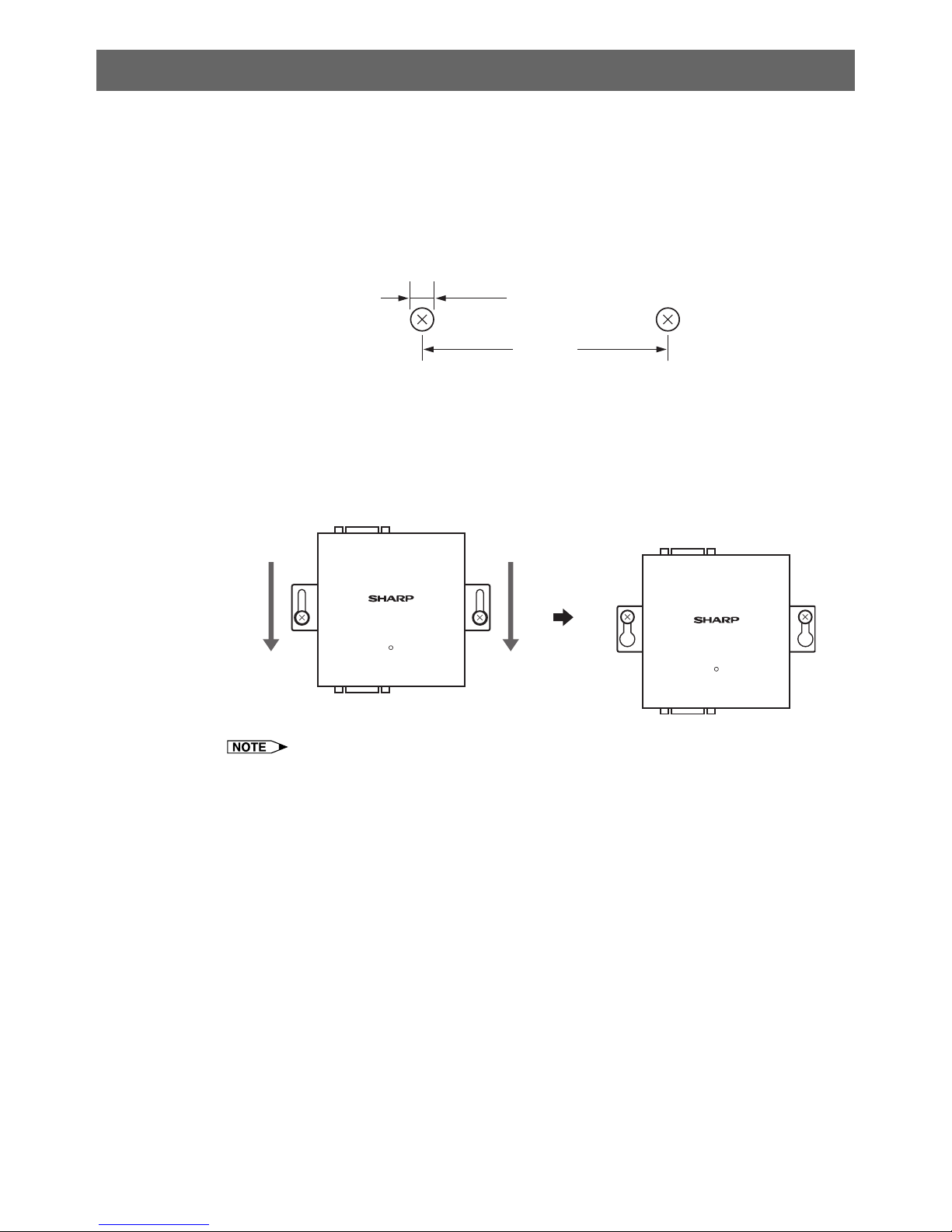
Wall Mount .......................................................................................................................................... 6
Connections
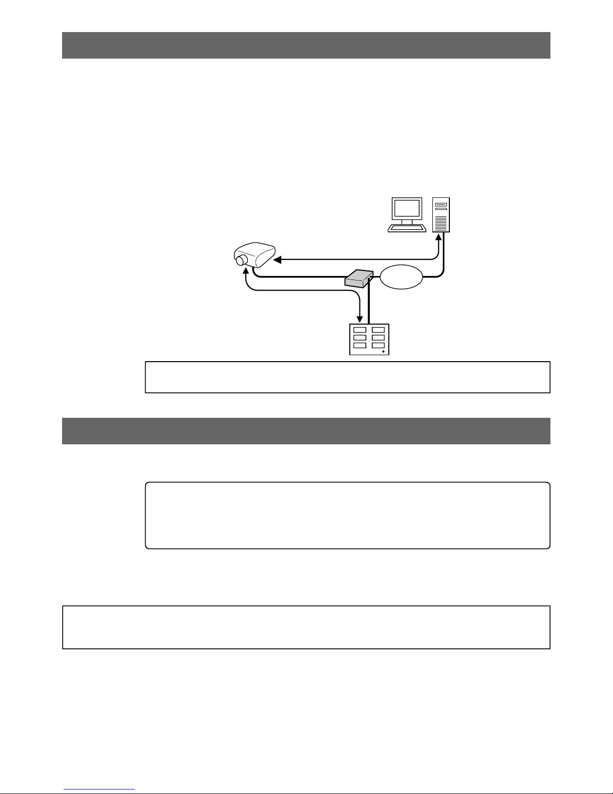
Overview ............................................................................................................................................ 7
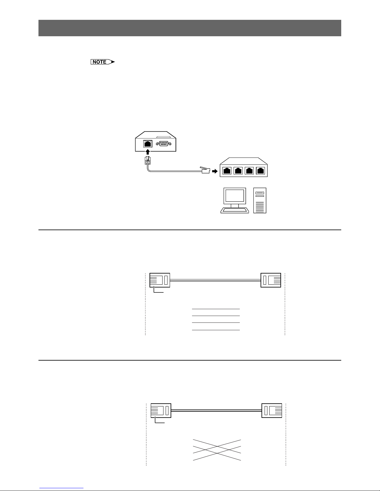
Connecting to an Ethernet LAN ......................................................................................................... 8
Connecting to a Hub or Switch ................................................................................................ 8
Connecting to a Computer ....................................................................................................... 8
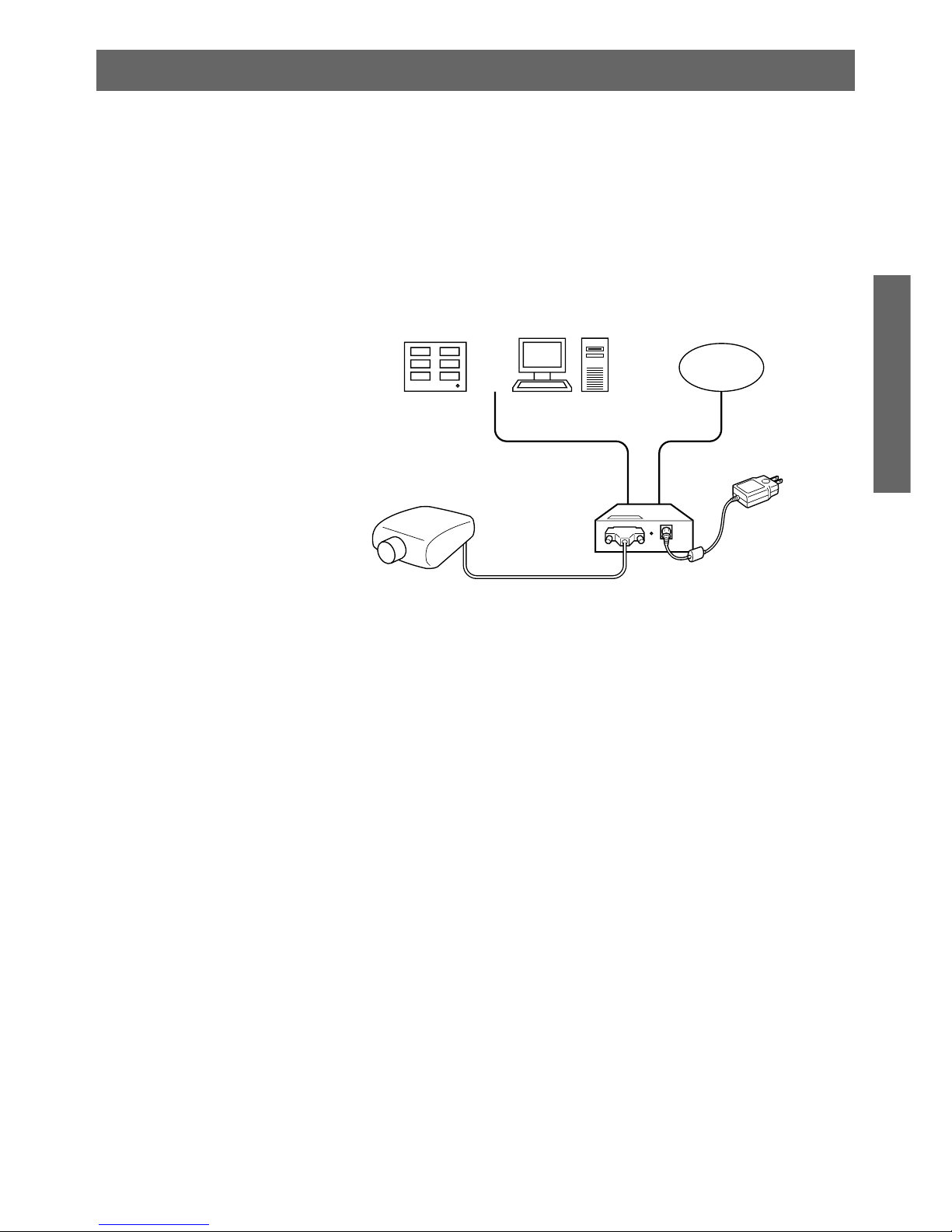
Connecting Devices ........................................................................................................................... 9
Connecting a Controller or a Computer ................................................................................... 9
Connecting a Projector ............................................................................................................ 9
Connecting the AC Adaptor .............................................................................................................. 10
Setup
Entering SETUP MENU ....................................................................................................................11
When Connecting Using RS-232C .........................................................................................11
When Connecting Using Telnet .............................................................................................. 12
SETUP MENU Description ............................................................................................................... 13
SETUP MENU (Main Menu) .................................................................................................. 13
ADVANCED SETUP MENU ................................................................................................... 14
Basic Procedure ............................................................................................................................... 15
Setting of Each Item ......................................................................................................................... 18
Using the Software
About Sharp COM Redirection Software ......................................................................................... 25
Installation ........................................................................................................................................ 26
Starting ............................................................................................................................................. 29
Explanation of the Screen ................................................................................................................ 30
Operations ........................................................................................................................................ 31
Search and Add...................................................................................................................... 31
Selecting Virtual COM Port .................................................................................................... 33
Add (Manual).......................................................................................................................... 35
Refresh ................................................................................................................................... 37
Delete ..................................................................................................................................... 38
Password ............................................................................................................................... 40
Setting .................................................................................................................................... 42
OK/Cancel .............................................................................................................................. 43
Changing / Removing the Software ................................................................................................. 44
Appendix
Connecting Pin Assignments ........................................................................................................... 46
Troubleshooting ................................................................................................................................ 47
Specifications ................................................................................................................................... 52
Index ................................................................................................................................................. 53

4
Part Names and Functions
Main Body
TX/RX LED indicator (Page 5)
Lit when transmitting data.
10BASE-T Ethernet terminal (Page 8)
To connect to an Ethernet LAN.
LINK LED indicator (Page 5)
Lit when link is active.
RS-232C terminal for controller (Page 9)
To connect a commercially available
controller or computer.
AN-LS1
POWER
RS-232C(CONTROLLER)
RS-232C(PROJECTOR) INIT. DC IN
TX/RX 10BASE-T LINK
POWER LED indicator (Page 5)
Lit when the power supply is on.
Wall mount screw holes (Page 6)
To be used for mounting AN-LS1 on a wall.
DC power input (Page 10)
To connect an AC adaptor.
Initialize (INIT.) button (Page 51)
To initialize the settings for AN-LS1 to the
factory default settings.
RS-232C terminal for projector (Page 9)
To connect a projector.
• To initialize the settings for AN-LS1
to the factory default settings,
connect the plug for the AC adapter
to a wall outlet to supply the power
while pressing the Initialize (INIT.)
button using a pointed tool.

5
Introduction
LED Indicators
The LED indicators at the side and on the top of AN-LS1 represent the contents in the following
table.
POWER
LINK
TX/RX
Name LED Color LED Function
POWER Green Power is on.
Off Power is off.
TX/RX Orange Network packets are being transmitted or received.
Off No network packet is being transmitted or received.
LINK Green AN-LS1 is connected to the network.
Off Ethernet cable is disconnected.

6
Wall Mount
You will find it convenient to mount AN-LS1 on the wall, using two screws, as indicated below.
1Screw two screws (not included) into the wall 96.5 mm apart.
The heads of the screws should be 5-7 mm in diameter, and the shafts should be 3 mm in diameter.
(It is recommended to use screws of 12 mm or more in length.) Do not screw the screws in all the
way—leave a space of about 4 mm to allow room for sliding AN-LS1’s ears between the wall and
the screws.
5-7 mm
96.5 mm
2Insert the two screw heads through the large parts of the keyhole shaped apertures,
and then slide AN-LS1 downwards, as indicated.
3For added stability, simply tighten the two screws.
AN-LS1
POWER
RS-232C(CONTROLLER)
RS-232C(PROJECTOR) INIT. DC IN
TX/RX 10BASE-T LINK
AN-LS1
POWER
RS-232C(CONTROLLER)
RS-232C(PROJECTOR) INIT. DC IN
TX/RX 10BASE-T LINK
•To remove AN-LS1 from the wall mount, simply reverse steps 2 and 3 above.

7
Connections
Overview
Use the following procedure for connection of AN-LS1.
1Connect AN-LS1 to an Ethernet LAN. (Page 8)
2Connect devices to AN-LS1. (Page 9)
•Connect a commercially available controller or computer.
•Connect a projector.
3Connect the AC adaptor. (Page 10)
Ethernet
LAN
12
32
Computer
or
Controller
Projector

8
Connecting to an Ethernet LAN
Connect AN-LS1 to a hub or a computer using a Category 5 cable.
•It is necessary to perform computer setting according to the network environment in advance.
•Default IP address and subnet mask of AN-LS1 are as follows:
IP address : 192.168.150.2
Subnet mask : 255.255.255.0
•When using AN-LS1 by connecting to an existing Ethernet LAN, and if there is any problem with
the above settings, change settings such as IP address by creating an independent network
without connecting to the existing Ethernet LAN or by connecting a computer to the RS-232C
(CONTROLLER) terminal.
After that, connect to the existing Ethernet LAN.
Category 5 cable (sold separately)
To Ethernet 10BASE-T or
100BASE-TX terminal
Hub
or
Computer
Connecting to a Hub or Switch
For most applications, you will simply plug one end of your Category 5 cable into the10BASE-T
terminal of AN-LS1. In this case, you should use a standard straight-through Category 5 cable, which
is readily available from many commercial vendors. If necessary, however, you can make your own
cable by referring to the following cable wiring diagram.
Straight-Through Cable
AN-LS1
RJ-45 Jack
Connector
Tx+
Tx-
Rx+
Rx-
1
2
3
6
1
2
3
6
Hub
RJ-45 Jack
Connector
Tx+
Tx-
Rx+
Rx-
Cable Wiring
RJ-45 Plug
Connecting to a Computer
In some cases, such as when configuring drivers and software, you will find it convenient to hook AN-
LS1 directly to your computer’s Ethernet terminal. To do this, you will need to use a cross-over Category
5 cable. This type of Category 5 cable is harder to find, although you can make your own cable by
referring to the following cable wiring diagram.
Cross-Over Cable
AN-LS1
RJ-45 Jack
Connector
Tx+
Tx-
Rx+
Rx-
1
2
3
6
1
2
3
6
PC Network adaptor
RJ-45 Jack
Connector
Tx+
Tx-
Rx+
Rx-
Cable Wiring
RJ-45 Plug

9
Connections
Connecting Devices
Connect a commercially available controller or computer and a projector to AN-LS1.
Connecting a Controller or a Computer
In the case of controlling a projector via RS-232C as well as via the Ethernet LAN, connect a
commercially available controller or computer to the RS-232C (CONTROLLER) terminal.
RS-232C (CONTROLLER)
Controller
(commercially available)
or
Computer
To RS-232C terminal
RS-232C serial control
cable
(commercially available)
•For connection procedures for each device, please refer to the operation manual for each device.
•Make sure not to connect a controller or a computer to the RS-232C (PROJECTOR) terminal.
•Set as follows for the Port settings for RS-232C.
Baud Rate : Set the same value as AN-LS1. (Page 11)
Data Length : 8 bits
Parity Bit : None
Stop Bit : 1 bit
Flow Control : None
•In the case of connecting to a controller, use a suitable cable for the RS-232C cable.
•In the case of connecting to a computer, use a cross-over type cable for the RS-232C cable.
Connecting a Projector
Connect a projector to the RS-232C (PROJECTOR) terminal.
RS-232C (PROJECTOR)
To RS-232C terminal
RS-232C serial control
cable
(commercially available)
Projector
•For connection procedures for a projector, please refer to the operation manual for the projector.
•In the case of connecting to a projector, use a cross-over type cable for the RS-232C cable.

10
Connecting the AC Adaptor
Take the following steps to connect AN-LS1’s AC adaptor.
1Plug the AC adaptor’s DC plug into AN-LS1’s DC IN jack.
2Plug the AC adaptor into wall outlet.
To wall outlet
•There is no on/off switch. AN-LS1 turns on as soon as the connected AC adaptor is plugged into
a wall outlet. The POWER LED indicator on AN-LS1’s top panel will light green to indicate that it
is receiving power.
CAUTION
•The AC adaptor may interfere with reception if used near a radio.
•Prevent flammables, liquids, and metal objects from entering the AC adaptor.
•The AC adaptor is a sealed unit. Do not attempt to open or modify it.
•Do not damage, drop, or subject the AC adaptor to vibration.
•Do not leave the AC adaptor in direct sunlight.
•Avoid using the AC adaptor in humid or extremely hot places.

11
Setup
Entering SETUP MENU
Connect AN-LS1 to a computer using RS-232C or Telnet, and open the “SETUP MENU”on the computer
to carry out various settings for AN-LS1.
When Connecting Using RS-232C
1Launch general purpose terminal emulator.
2Set settings for the RS-232C port of the terminal emulator as follows.
Baud Rate : *9600 bps
Data Length : 8 bit
Parity Bit : None
Stop Bit : 1 bit
Flow Control : None
* This is the default value. If the value of Baud Rate for AN-LS1 has been changed, set Baud Rate
here according to the changed value on AN-LS1. (Page 19)
3Connect the plug for the AC adapter to a wall outlet to supply the power while holding
down the “A”(or “a”) key on the terminal keyboard.
4Keep holding down the“A”(or“a”) key for more than 3 seconds.“Setup Menu Enable”
will be displayed.
5Press the return key on the terminal keyboard.
6Input “setup”and press the return key.
7“User Name:”is displayed. Input the user name and press the return key.
(If a user name has not yet been set, just press the return key.)
8“Password:”is displayed. Input the password and press the return key.
(If a password has not yet been set, just press the return key.)
9Input “setup”and press the return key.
|SETUP MENU will be displayed.
S E T U P M E N U
[1]IP Address [2]Subnet Mask [3]Default Gateway
[4]User Name [5]Password
[6]RS-232C Baud Rate [7]Unit Name
[A]Advanced Setup [D]Disconnect All
[V]View All Setting [S]Save & Quit [Q]Quit Unchanged
setup>
•User name and password are not set in the initial settings.
•If the user name or password is entered incorrectly three times, SETUP MENU will be quit.

12
When Connecting Using Telnet
1Click “Start” from the Windows desktop and select “Run”.
2Enter “telnet 192.168.150.2” in the text box that opens up.
(If the IP address of the unit is 192.168.150.2.)
3Click “OK”.
4“User Name:” is displayed. Input the user name and press the return key.
(If a user name has not yet been set, just press the return key.)
5“Password:” is displayed. Input the password and press the return key.
(If a password has not yet been set, just press the return key.)
6Input “setup” and press the return key.
|SETUP MENU will be displayed.
S E T U P M E N U
[1]IP Address [2]Subnet Mask [3]Default Gateway
[4]User Name [5]Password
[6]RS-232C Baud Rate [7]Unit Name
[A]Advanced Setup [D]Disconnect All
[V]View All Setting [S]Save & Quit [Q]Quit Unchanged
setup>
•If the IP address has been changed, be sure to enter the correct IP address.
•User name and password are not set in the initial settings.
•If the user name or password is entered incorrectly three times, SETUP MENU will be quit.

13
Setup
SETUP MENU Description
SETUP MENU (Main Menu)
S E T U P M E N U
[1]IP Address [2]Subnet Mask [3]Default Gateway
[4]User Name [5]Password
[6]RS-232C Baud Rate [7]Unit Name
[A]Advanced Setup [D]Disconnect All
[V]View All Setting [S]Save & Quit [Q]Quit Unchanged
setup>
[1] IP Address (Factory default setting : 192.168.150.2)
IP address settings. (Page 18)
[2] Subnet Mask (Factory default setting : 255.255.255.0)
Subnet mask settings. (Page 18)
[3] Default Gateway (Factory default setting : Not Used)
Default gateway settings. (Page 18)
[4] User Name (Factory default setting : Not Required)
Setting of user name for security protection. (Page 19)
[5] Password (Factory default setting : Not Required)
Setting of password for security protection. (Page 19)
[6] RS-232C Baud Rate (Factory default setting : 9600 bps)
Baud rate settings for the RS-232C terminals. (Page 19)
[7] Unit Name (Factory default setting : AN-LS1)
It is possible to assign a unit name. (Page 20)
[A] Advanced Setup
Enters ADVANCED SETUP MENU. (Page 20)
[D] Disconnect All
Disconnect all connections. (Page 20)
[V] View All Setting
Displays all setting values. (Page 15)
Can also be used with advanced menu.
[S] Save & Quit
Save set values and quit menu. (Page 17)
[Q] Quit Unchanged
Quit menu without saving setting values. (Page 17)

14
ADVANCED SETUP MENU
******************** ADVANCED SETUP MENU ***********************
[1]Auto Logout Time [2]COM Redirect Port [3]Busy Reply
[4]Input Hold Time [5]Network Ping Test
[6]Accept IP Addr(1) [7]Accept IP Addr(2) [8]Accept IP Addr(3)
[9]Accept All IP Addr [0]Port for Search
[!]Restore Default Setting
[Q]Return to Main Menu
advanced>
[1] Auto Logout Time (Factory default setting : 5 minutes)
Setting of time until automatic disconnection of network connection. (Page 21)
[2] COM Redirect Port (Factory default setting : 10002)
Setting of TCP port No. capable of connecting using Sharp COM Redirection Software. (Page 21)
[3] Busy Reply (Factory default setting : ERR + <CR> code)
When separate devices are connected to the two control terminals (RS-232C (CONTROLLER)
and 10BASE-T), it is not possible to use one control terminal while data is being transmitted using
the other control terminal.
This setting is for operation of the control terminal that cannot be used.
(Page 22)
[4] Input Hold Time (Factory default setting : 1000 milliseconds)
Changing value for Input Hold Time when a response is not returned from a projector within a set
time while separate devices are connected to the two control terminals (RS-232C (CONTROLLER)
and 10BASE-T). (Page 22)
[5] Network Ping Test
It is possible to confirm that a network connection between AN-LS1 and a computer etc. is working
normally. (Page 23)
[6] Accept IP Addr(1)
[7] Accept IP Addr(2)
[8] Accept IP Addr(3)
[9] Accept All IP Addr (Factory default setting : Accept All)
For improved security, it is possible to set up to three IP addresses allowing connection to AN-
LS1. Set IP addresses can be cancelled using [9] Accept All IP Addr. (Page 23)
[0] Port for Search (Factory default setting : 5006)
Setting for port number used when Sharp COM Redirection Software searches for AN-LS1. (Page
24)
[!] Restore Default Setting
Restores all setting values that can be set using the menu to the default state.
(Page 24)
[Q] Return to Main Menu
Return to the main SETUP MENU. (Page 24)

15
Setup
Basic Procedure
Enter number or symbol of item to be selected on the “SETUP MENU”. When setting, input the details
to be set. Setting is carried out one item at a time, and saved at the end.
View Setting Detail List ([V]View All Setting)
Displays all setting values.
▼The SETUP MENU
———————— S E T U P M E N U ——————————
[1]IP Address [2]Subnet Mask [3]Default Gateway
[4]User Name [5]Password
[6]RS-232C Baud Rate [7]Unit Name
[A]Advanced Setup [D]Disconnect All
[V]View All Setting [S]Save & Quit [Q]Quit Unchanged
setup>v
Model Name : AN-LS1
Unit Name : AN-LS1
MAC Address : 08:00:1f:b1:b7:74
IP Address : 192.168.150.2
Subnet Mask : 255.255.255.0
Default Gateway : Not Used
RS-232 Baud Rate : 9600 bps
Password : Not Required
**********(Advanced Status)**********
COM Redirect Port : 10002
Accept IP Address : Accept All
Busy Reply : ERR+<CR> code
Input Hold Time : 1000 milliseconds
Auto Logout Time : 5 minutes
Port for Search : 5006
Display the current setting detail
list.
Enter “v”and press the return key.

16
Set Items
(e.g.) When setting IP Address (change from 192.168.150.2 to 192.168.150.3)
▼The SETUP MENU
———————— S E T U P M E N U ——————————
[1]IP Address [2]Subnet Mask [3]Default Gateway
[4]User Name [5]Password
[6]RS-232C Baud Rate [7]Unit Name
[A]Advanced Setup [D]Disconnect All
[V]View All Setting [S]Save & Quit [Q]Quit Unchanged
setup>1
IP Address : 192.168.150.2
Please Enter : 192.168.150.3
(change) —> 192.168.150.3
———————— S E T U P M E N U ——————————
[1]IP Address [2]Subnet Mask [3]Default Gateway
[4]User Name [5]Password
[6]RS-232C Baud Rate [7]Unit Name
[A]Advanced Setup [D]Disconnect All
[V]View All Setting [S]Save & Quit [Q]Quit Unchanged
setup>v
Model Name : AN-LS1
Unit Name : AN-LS1
MAC Address : 08:00:1f:b1:b7:74
IP Address : 192.168.150.3
Subnet Mask : 255.255.255.0
Default Gateway : Not Used
RS-232C Baud Rate: 9600 bps
Password : Not Required
**********(Advanced Status)**********
COM Redirect Port : 10002
Accept IP Address : Accept All
Busy Reply : ERR+<CR> code
Input Hold Time : 1000 milliseconds
Auto Logout Time : 5 minutes
Port for Search : 5006
•Verification of setting detail list can be omitted.
•Setting details are not effective until they have been saved. (Page 17)
•If an invalid number is entered, an error message (“Parameter Error!”) will be displayed.
Display IP address after
change.
Enter IP address to be set and
press the return key.
Display current IP address.
Enter “1”(number of item to be
set), and press the return key.
Enter “v”and press the return
key to verify setting detail list.
IP address is being changed.

17
Setup
Quit
Save settings and quit. ([S]Save & Quit)
Save set values and quit menu.
▼The SETUP MENU
———————— S E T U P M E N U ——————————
[1]IP Address [2]Subnet Mask [3]Default Gateway
[4]User Name [5]Password
[6]RS-232C Baud Rate [7]Unit Name
[A]Advanced Setup [D]Disconnect All
[V]View All Setting [S]Save & Quit [Q]Quit Unchanged
setup>s
All Connection will be disconnect.
Continue(y/n)? y
Apply New setting...Done.
Quit without saving settings. ([Q]Quit Unchanged)
Quit menu without saving setting values.
▼The SETUP MENU
———————— S E T U P M E N U ——————————
[1]IP Address [2]Subnet Mask [3]Default Gateway
[4]User Name [5]Password
[6]RS-232C Baud Rate [7]Unit Name
[A]Advanced Setup [D]Disconnect All
[V]View All Setting [S]Save & Quit [Q]Quit Unchanged
setup>q
Quit Without Saving(y/n)? y
Setting Unchanged.
Enter “s”and press the return key.
Enter “y”and press the return key.
Enter “q”and press the return key.
Enter “y”and press the return key.

18
Setting of Each Item
The setting procedure for each item will be explained. For the basic procedure, please refer to page
15.
IP Address Setting ([1]IP Address)
Setting of IP address.
setup>1
IP Address :192.168.150.2
Please Enter :192.168.150.3
(change) —> 192.168.150.3
Subnet Mask Setting ([2]Subnet Mask)
Setting subnet mask.
setup>2
Subnet Mask :255.255.255.0
Please Enter :255.0.0.0
(change) —> 255.0.0.0
Default Gateway Setting ([3]Default Gateway)
Setting default gateway.
setup>3
note: “0.0.0.0”means “Using no default gateway.”
Gateway Address :0.0.0.0
Please Enter :192.168.150.1
(change) —> 192.168.150.1
•If operations on this page are performed while changing the setting for AN-LS1 via Telnet, there may be
situations where AN-LS1 cannot be connected depending on the network setting for the computer for control
since the set values for IP Address, Subnet Mask or Gateway are restored to the initial state.
Enter numerical value to be set
and press the return key.
Enter “1”and press the return key.
Enter numerical value to be set
and press the return key.
Enter “2”and press the return key.
Enter numerical value to be set
and press the return key.
Enter “3”and press the return key.
Display gateway address after
change.
Display subnet mask after
change.
Display IP address after
change.

19
Setup
User Name Setting ([4]User Name)
Carrying out security protection using user name.
setup>4
User Name :
Please Enter : an-ls1
(change) —> an-ls1
•User name can be up to 8 characters.
•In the initial state, user name is not set.
Password Setting ([5]Password)
Carrying out security protection using password.
setup>5
Password :
Please Enter : sharppj
(change) —> sharppj
•Password can be up to 8 characters.
•In the initial state, the password is not set.
RS-232C Baud Rate Setting ([6]RS-232C Baud Rate)
Setting of baud rate for RS-232C (CONTROLLER and PROJECTOR) terminals.
setup>6
note: It sets both RS-232C (CONTROLLER) and RS-232C (PROJECTOR).
0 ... 9600 bps
1 ... 38400 bps
2 ... 115200 bps
Baud Rate Select[0-2] :1
RS-232C Baud Rate : 38400 bps
•Baud Rates for the RS-232C (CONTROLLER) terminal and the RS-232C (PROJECTOR) terminal
cannot be set to different values.
Display set user name.
Enter user name and press the
return key.
Enter “4”and press the return key.
Display set password.
Enter password and press the
return key.
Enter “5”and press the return key.
Display set baud rate.
Select and enter the number 0, 1,
or 2 and press the return key.
Enter “6”and press the return key.

20
Unit Name Setting ([7]Unit Name)
It is possible to assign a unit name.
When searching using Sharp COM Redirection Software, it is possible to verify a communication
destination using the unit name.
setup>7
Unit Name : AN-LS1
Please Enter : My An-ls1
(change) —> My An-ls1
•Unit name can be up to 12 characters.
Disconnecting All Connections ([D]Disconnect All)
It is possible to disconnect all the TCP/IP connections currently recognized by AN-LS1. Even if the
COM Redirect port is fixed in the Busy status due to a problem, it is possible to force the Ready status
back by carrying out this disconnection. (Page 51)
setup>d
Disconnect All Connections(y/n)?y
Now Disconnecting...
•If Disconnect All is performed while Sharp COM Redirection Software or the Telnet menu is in
use, Sharp COM Redirection Software will be forcibly terminated or the connection via Telnet will
be disconnected.
Entering ADVANCED SETUP MENU ([A]Advanced Setup)
Enters ADVANCED SETUP MENU.
setup>a
****************** ADVANCED SETUP MENU *********************
[1]Auto Logout Time [2]COM Redirect Port [3]Busy Reply
[4]Input Hold Time [5]Network Ping Test
[6]Accept IP Addr(1) [7]Accept IP Addr(2) [8]Accept IP Addr(3)
[9]Accept All IP Addr [0]Port for Search
[!]Restore Default Setting
[Q]Return to Main Menu
advanced>
Display set unit name.
Enter unit name.
Enter “7”and press the return key.
Enter “y”and press the return key.
Enter “d”and press the return key.
Enter “a”and press the return key.
Other manuals for AN-LS1
1
Table of contents
Other Sharp Media Converter manuals

Sharp
Sharp CE-133T User manual

Sharp
Sharp DK-A10P User manual

Sharp
Sharp CD-BP2000W User manual

Sharp
Sharp CE-130T User manual

Sharp
Sharp AN-LS1 User manual

Sharp
Sharp RT-XV300H B C User manual

Sharp
Sharp DK-AP8P User manual

Sharp
Sharp CD-BK1600V User manual

Sharp
Sharp TU-DTV1000/A User manual

Sharp
Sharp DK-AP7P - Portable Speakers With Digital Player... User manual