Sharp R-1874TYA User manual

1
R-1874TYA
UPDATE
In the interest of user-safety the unit should be restored to its original condition and only parts identical to those specified should
be used.
WARNING TO SERVICE PERSONNEL:
This service manual is intended for use by persons having electrical and mechanical training and a level of
knowledge of these subjects generally considered acceptable in the appliance repair trade. Sharp Electronics
Corporation cannot be responsible, nor assume any liability, for injury or damage of any kind arising from the
use of this manual.
Microwave ovens contain circuitry capable of producing very high voltage and current. Contact with the
following parts may result in a severe, possibly fatal, electrical shock. (High Voltage Capacitor, High Voltage
Power Transformer, High Voltage Rectifier, Heat sink, Magnetron, and High Voltage Harness etc..)
OVER THE RANGE MICROWAVE MODEL
SUPPLEMENTAL SERVICE MANUAL
This document has been published to be used for after sales service only. The contents are subject to change without notice.
SHARP ELECTRONICS CORPORATION
R-1874TYA
This is a supplemental Service Manual for Model R-1874TYA. Use this supplemental manual together with
the following base model for complete operation, service information, etc. R-1874TY S42M323R18OR4Y
(base model R-1855).
*FOR SERIAL NUMBERS: 514495 ~ AND ABOVE
Units with Serial Number range 514495 ~ and above employ a change to the
connectors on various Components, Harnesses and PWB’s.
Use this Service Manual for all units with the Serial Number range
514495 ~ and above.
*NOTE:

2
UPDATE R-1874TYA
SHARP ELECTRONICS OF CANADA LTD. HEAD OFFICE
335 BRITANNIA ROAD EAST
MISSISSAUGA ON L4Z 1W9
SUPPLEMENTAL SERVICE MANUAL
OVER THE COUNTER MICROWAVE OVEN
R-1874TYA
FOREWORD
This Manual has been prepared to provide Sharp Electronics Corp. Service Personnel with Operation and Service Informa-
tion for the SHARP OVER THE RANGE MICROWAVE OVEN.
It is recommended that service personnel carefully study the entire text of this manual so that they will be qualified to render
satisfactory customer service.
Check the interlock switches and the door seal carefully. Special attention should be given to avoid electrical shock and
microwave radiation hazard.
WARNING
Never operate the oven until the following points are ensured.
(A) The door is tightly closed.
(B) The door brackets and hinges are not defective.
(C) The door packing is not damaged.
(D) The door is not deformed or warped.
(E) There is not any other visible damage with the oven.
Servicing and repair work must be carried out only by trained service personnel.
DANGER
Certain initial parts are intentionally not grounded and present a risk of electrical shock only during servicing.
Service personnel - Do not contact the following parts while the appliance is energized;
HighVoltage Capacitor, PowerTransformer, Magnetron, HighVoltage Rectifier Assembly, HighVoltage Harness;
If provided, Vent Hood, Fan assembly, Cooling Fan Motor.
All the parts marked “*” on parts list are used at voltages more than 250V.
Removal of the outer wrap gives access to voltage above 250V.
All the parts marked “∆” on parts list may cause undue microwave exposure, by themselves, or when they are dam-
aged, loosened or removed.
BEFORE SERVICING
Before servicing an operative unit, perform a microwave emission check as per the Microwave Measurement
Procedure outlined in this service manual.
If microwave emissions level is in excess of the specified limit, contact SHARP ELECTRONICS OF CANADA
LTD. immediately @(800) 837-0256.
TO ACCESS INTERNET: http://www.sharp.ca/contact-callus.aspx
If the unit operates with the door open, service person should 1) tell the user not to operate the oven and 2)
contact SHARP ELECTRONICS OF CANADA LTD. and NHW CANADA immediately.
Service personnel should inform SHARP ELECTRONICS OF CANADA LTD. of any certified unit found with
emissions in excess of 4mW/cm2. The owner of the unit should be instructed not to use the unit until the oven

3
R-1874TYA
UPDATE
Oven Schematic - Off Condition
SCHEMATIC
NOTE: CONDITION OF OVEN
1. Door Closed
2. CLOCK APPEARS ON DISPLAY
Circuits / Wire colors subject to change without notice
RY10
RY9
RY6
B5
A5
SWITCH
INTERLOCK
SECONDARY
HOOD
CUTOUTS
THERMAL
HOOD FAN
C1
CAPACITOR
A3
CONTROL UNIT
N.O.
C3
FAN MOTOR
OL
120VAC
60Hz
MOTOR
HOOD
A1
GND
C5
C7
DM
RY1
TTM
OVEN LAMP
CM
COM.
STIRRER MOTOR
TEMPERATURE
FUSE
MAGNETRON
F1 F2 F3
AH SENSOR
CONVECTION MOTOR
MONITOR
HEATING
ELEMENT
SWITCH
FM
RY7
RY4
RY5
VOLTAGE
HIGH
CAPACITOR
MAGNETRON
HIGH
VOLTAGE
RECTIFIER
TRANSFORMER
POWER
NOISE
RESISTOR
C9
RY8
TURNTABLE MOTOR
DAMPER MOTOR
B7
RY1
STM
RY3 RY2
COM.
RY2
COM.
RY3
RY2
N.O.
RY1
DAMPER
THERMISTOR SWITCH
SENSING
SWITCH
DOOR
N.O.
RY3 E5
E1 E2 E6 E3 E4
PRIMARY INTERLOCK RELAY
MONITOR
FUSE (20A)
NOISE
FILTER
(CONV. SIDE)
THIRD DOOR
SWITCH
HOOD
LAMP
HL
HL
C1 C2
C3
CN201
#1(+)
#2(-)
B1
B3
VRS1
CN101
#3(L)
#1(N)
SWITCHING
D5 D3
REGULATOR
D1 D7
FUSE1
H
N
1. Check AC power into CN101,
if none check Main Harness.
2. Check DC power across CN201 (DC15V),
if none replace Switching Power Supply Unit
3. Check for DC getting from Switching Power
Supply Unit to PSU/ CPU, if none check Main
Harness.
SWITCHING POWER SUPPLY TEST PROCEDURE
CN101
CN201

4
UPDATE R-1874TYA
6
54
123
6
54
123
A
B
C
D
E
F
G
H
A
B
C
D
E
F
G
H
Pictorial Diagram
HIGH VOLTAGE
CAPACITOR
H.V.
RECTIFIER
HIGH VOLTAGE COMPONENTS
MAGNETRON
POWER TRANSFORMER
FFA
Power Supply
cord 120V 60Hz
GRN
BLK
1
2
3
WHT
GRN
BLK
HOOD FAN
THERMAL
CUT-OUT
CONVECTION
MOTOR
HEATING
ELEMENT
THERMISTOR
TEMPERATURE FUSE (MG.)
B
L
K
R
E
D
B
R
N
O
R
G
WHT
BLK
BRN
WHT
FAN
MOTOR
DAMPER
MOTOR
DAMPER
SWITCH
TURNTABLE
MOTOR
GRY
GRY
WHT
BRN
HOOD LAMPS
& SOCKETS
Blue
Marking
Blue Marking
OVEN LAMP & SOCKET
to oven cavity
front flange
CN-E
CN-F
1
2
YLW
ORG
CN-A
5
4
RED
ORG
YLW
BRN
BLU
SECONDARY
INTERLOCK
SWITCH
N.O.
N.C.
COM.
COM.
MONITOR
SWITCH
N.O.
N.O.
COM.
COM.
GRN
GRN PNK
N.O.
COM.
DOOR SENSING SWITCH
CN-C
CN-E
CN-F
CN-A
RY3
RY1
RY9
RY7
1
2RED
WHT
3AH. SENSOR HOOD FAN MOTOR
STIRRER MOTOR
WHT
BLK
BLK
BLK
BLK 1
2
1
2
3
4
5
6
WHT
RED
YLW
BLU
BLK
BLU
YLW
RED
GRY
PPL
1
2
3
4
5
6
BRN
BLK
BLK
BLK
WHT
PNK
GRN
1
2
3
4
5
6
7
BLK
ORG
GRY
RED
CN-B
GRY
ORG
BLK
RED
ORG
WHT
RED
BLU
ORG
PPL
WHT
ORG
Y
L
W
RED
PPL
PPL
GRN
GRN
1
2
3
4
5
6
7
BLK
PPL
BLU
PNK
8
9BRN
CN-C
3
N.O.
COM.
RY2
N.O.
COM.
CN-B
CN-G
RY10
RY8
RY6
RY5
RY4
BRN
BRN
BLU
COM.
N.O.
THIRD
DOOR
SWITCH YLW
RED
RED RED
GRY
BLK
WHT
GRY
WHT
B
R
N
Y
L
W
B
R
N
P
K
NOISE
RESISTOR
THERMAL
CUT-OUT
NOISE FILTER
BOARD
N
H
YLW
YLW
ORG
BLK
BLK
BRN
R
E
D
CN101
1
2
BLK
CN201
RED
1
2
3ORG
CN101
GRY
CN201
SW POWER
SUPPLY
CN-D
1
2
3
4
5
6
7
WHT
CN-D
P
N
K
GRY
PNK PNK
PPL
BLU
GRY
WHT
WHT
GRY
N
BRN
PNK
ORG
O
R
G

5
R-1874TYA
UPDATE
PARTS LIST
Note: The parts marked “∆” may cause undue microwave exposure.
The parts marked “*” are used in voltage more than 250V.
REF. NO. PART NO. DESCRIPTION Q'TY CODE
*
*
∆*
ELECTRIC PARTS
1- 1 FC-QZA622WRKZ High voltage capacitor assembly 1 AX
1- 2 FPWBFA515WRKZ Noise lter 1 AN
1- 3 QFS-TA013WRE0 Temperature fuse 150°C 1 AG
1- 4 RMOTDA256WRZZ Damper motor 1 AP
1- 5 RMOTDA252WRZZ Turntable motor 1 AN
1- 6 RMOTDA258WRZZ Stirrer motor 1 AQ
1- 7 RTHM-A181WRZZ Thermal cut-out N.O. 60°C 2 AF
1- 8 RTRN-B092MRE0 Power transformer 1 BK
1- 9 RV-MZA407WRZZ Magnetron 1 BC
1-10 DPWB-B451DRKZ Switching power supply 1 AZ
1-11 QSW-MA085WRE0
Damper switch
1 AF
1-12 QFS-BA009WRE0 Fuse 20A (order with 1-24) 1 AF
1-13 FACCDA130WREZ Power supply cord 1 AP
1-14 QSOCLB010MRE0 Hood lamp socket 2 AH
1-15 FDTCTA261WRKZ AH sensor 1 AP
1-16 QSOCLA021WRE0 Oven lamp socket 1 AG
1-17 FMOTEA582WRKZ Hood fan motor 1 BE
1-18 RR-WZA031WRE0 Noise resistor 1 AP
1-19 RMOTEB032MRE0 Fan motor 1 AZ
1-20 RLMPTA086WRZZ Hood lamp and oven lamp 3 AL
1-21 RC-QZA331WRZZ HV capacitor 1 AR
1-22 FH-DZB032MRY0 HV rectier 1 AM
1-23 QSW-MA168WRZZ Switches 3 AF
1-24 QSW-MA169WRZZ Monitor switch 1 AD
CABINET PARTS
2- 1 PFIL-B005MRE0 Grease lter 2 AM
2- 2 FDIF-B013MRK0 Hood exhaust louver 1 AY
2- 3 GDAI-A463WRWZ Base plate right 1 AQ
2- 4 GDAI-A462WRWZ Base plate left 1 AM
2- 5 FCABUA989WRKZ Outer case cabinet 1 BG
2- 6 TMAPCA834WRRZ Schematic diagram 1 AE
2- 7 FANGKB009MRY0 Hood lamp glass assembly 1 AP
2-7-1 LANGQB016MRP0 Hood lamp glass angle 1 AM
2-7-2 PGLSPB004MRE0 Hood lamp glass 1 AQ
2- 8 PCOVPA565WRTZ Base cover 1 BA
2- 9 FDECAB028MRK0 Sash left 1 AR
2-10 LSTY-A122WRWZ Rear stay 1 AK
CONTROL PANEL PARTS
3- 1 CPWBFB151MRU8 Control unit 1 BG
3- 2 FPNLCB407MRK0 Control panel sub. assembly 1 BF
3- 3 MSPRCA045WRE0 Open button spring 1 AA
3- 4 FDECAB029MRK0 Open button assy 1 AT
3- 5 XEPS730P08XS0 Screw 3 AB
3- 6 XHPS730P08XS0 Screw 2 AB
OVEN PARTS
4- 1 FFTA-B004MRK0 Exhaust damper assembly 1 AM
4- 2 FROLPB027MRK0 Turntable support assembly 1 AX
4- 3 NTNT-A146WREZ Turntable tray 1 AY
4- 4 LANGKB463WRPZ Capacitor holder 1 AF
4- 5 FCOVPA068WRYZ Stirrer cover assembly 1 AQ
4- 6 FFAN-A002WRKZ Stirrer fan assembly 1 AR
4- 7 ------------- Oven cavity (not replaceable) 1 -
4- 8 DHET-B002MRK01 Convection heater unit 1 BS
4- 9 NCPL-B007MRF0 Coupling 1 AN
4-10 PCUSGA786WRPZ Cushion 2 AH
4-11 PCUSUA663WRPZ Cushion 1 AH
4-12 PPACGA189WREZ Turntable motor packing 1 AG
4-13 PCUSUA662WRPZ Cushion 2 AH
4-14 PFPF-A313WREZ Heat protect 1 AQ
4-15 PHOK-A182WRFZ Latch hook 1 AG

6
UPDATE R-1874TYA
REF. NO. PART NO. DESCRIPTION QTY CODE
4-16 FANGTA175WRYZ Unit mounting plate 1 AY
4-17 PFPF-A310WREZ Heat protect 1 AH
4-18 LANGQA811WRPZ Noise lter angle 1 AF
4-19 PDUC-B161WRWZ Exhaust duct B 1 AF
4-20 PDUC-B167WRWZ Hood intake duct L 1 AK
4-21 NFANJA069WREZ Fan blade 1 AG
4-22 GBDYRA014WRWZ Back plate 1 AX
4-23 FDUC-A506WRKZ Fan duct 1 AP
4-24 LBSHCA014WRE0 Cord bushing 1 AG
4-25 FDUC-A509WRKZ Exhaust duct 1 AZ
4-26 MLEVPB016MRF1 Open lever 1 AD
4-27 PCUSGA788WRPZ Cushion 1 AF
4-28 MCAMPA187WRFZ Damper cam 1 AF
4-29 PCUSUA666WRPZ Damper cushion 1 AF
4-30 PFPF-A310WREZ Heat protect R 1 AH
4-31 PFTA-A041WRPZ Damper plate 1 AF
4-32 PREFHA091WRWZ Thermal cover R 1 AQ
4-33 LANGQA812WRPZ Hood lamp angle 1 AK
4-34 PREFHA092WRPZ Thermal cover bottom 1 AP
4-35 LSTPPB024MRF0 Door stopper 1 AF
4-36 PCOVPA558WRWZ Oven lamp cover 1 AG
4-37 PCOVPA559WRPZ Heat protect top sheet 1 AK
4-38 PCUSGA789WRPZ Cushion 1 AF
4-39 PDUC-B162WRFZ Hood exhaust duct 1 AZ
4-40 PDUC-B165WRPZ Top duct 1 AR
4-41 PDUC-B164WRFZ Magnetron duct 1 AH
4-42 PDUC-B166WRPZ Hood intake duct R 1 AM
4-43 PFILWA035WRE0 Oven light screen 1 AK
4-44 PFPF-A312WREZ Heat protect top 1 AR
4-45 PCUSUA673WRPZ Exhaust cushion A 1 AE
4-46 PCUSGA792WRPZ Exhaust cushion B 2 AF
4-47 PCUSUA668WRPZ Cushion 1 AF
4-48 PCUSUA669WRPZ Cushion 2 AF
4-49 PCUSUA670WRPZ Cushion 1 AF
4-50 LHLDPB004MRF0 PWB holder 1 AC
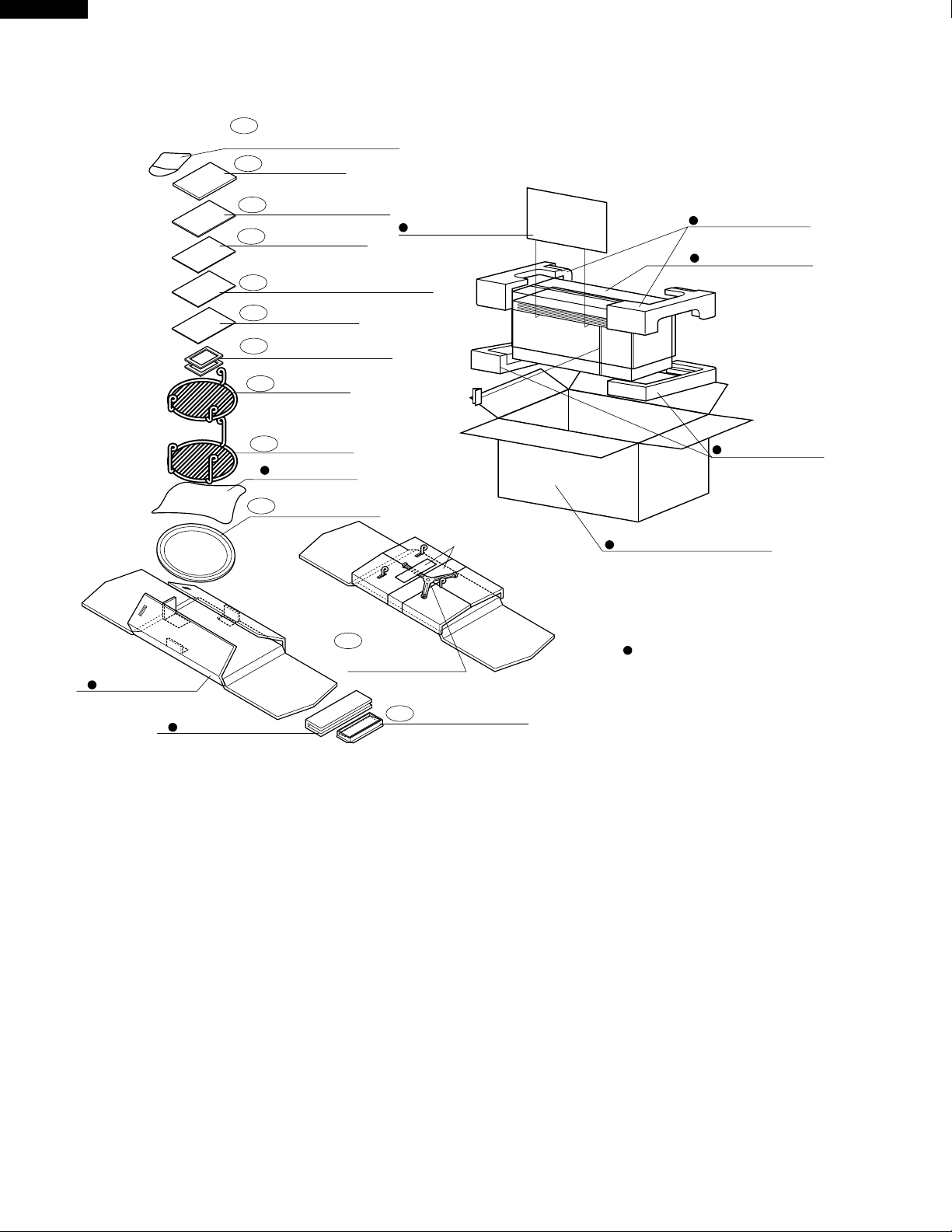
DOOR PARTS
5- 1 CDORFB312MRK0 Door assembly 1 BR
5- 2 GCOVHB031MRF0 Choke cover 1 AY
5- 3 LSTPPB025MRF0 Latch head 1 AH
5- 4 MSPRTA046WRE0 Latch spring 1 AD
MISCELLANEOUS
6- 1 CFZK-B659WRKZ Installation material assembly 1 AW
6-1-1 LBSHC0040MRE0 Grommet 1 AF
6-1-2 LX-BZ0195WRE0 Toggle screw 4 AH
6-1-3 XBRS750P60000 Screw : 5mm x 60mm 2 AK
6-1-4 XOTS740P12000 Screw : 4mm x 12mm 1 AB
6-1-5 XTSS750P35000 Screw : 5mm x 35mm 6 AD
6-1-6 XWHS750-16300 Washer 2 AG
6- 2 TINSEB235WRRZ Installation instruction 1 AR
6- 3 TINSEB388WRRZ Operation manual 1 AK
6- 4 TINSKA031WRRZ Top template 1 AK
6- 5 TINSKA032WRRZ Wall template 1 AK
6- 6 QW-QZB011MRE0 High voltage wire A 1 AF
6- 7 TCADCB020WRRZ Cook book 1 AR
6- 8 FW-VZC506WREZ Main harness 1 BA
6- 9 FAMI-B006MRM0 High rack 1 AU
6-10 FAMI-B005MRM0 Low rack 1 AU
6-11 TCAUAA304WRRZ User caution label 1 AC
6-12 TCAUAA382WRRZ Caution label HWC 1 AF
6-13 TCAUAA307WRRZ DHHS caution label 2 AD
6-14 TCAUAA305WRRZ NHW caution label 1 AD
6-15 TCAUAA366WRRZ Monitor caution label 1 AF

7
R-1874TYA
UPDATE
REF. NO. PART NO. DESCRIPTION Q'TY CODE
SCREWS,NUTS AND WASHERS
7- 1 XHPS740P08K00 Screw 8 AC
7- 2 XOTS840P08000 Screw 4 AB
7- 3 XHPS730P08000 Screw 5 AC
7- 4 XBTS740P08RV0 Screw 2 AD
7- 5 XCTWW40P08RV0 Screw 2 AB
7- 6 XBTWW40P06000 Screw 2 AA
7- 7 XOTS740P08000 Screw 24 AB
7- 8 XHTS740P08000 Screw 2 AC
7- 9 XHTS740P08RV0 Screw 2 AG
7-10 LX-BZB011MRE0 Unit mounting screw 2 AT
7-11 LX-CZB025MRE0 Hood louver Screws 2 AE
7-12 XCBWW30P06000 Screw 8 AB
7-13 LX-CZ0052WRE0 Special screw 2 AA
7-14 XOTWW40P10000 Screw 14 AB
7-15 XEPS730P08XS0 Screw 2 AA
MISCELLANEOUS PARTS
6-6
6-8
6-9 6-10
6-1
6-1-1
6-1-2
6-1-3
6-1-5
6-1-6
6-1-4

8
UPDATE R-1874TYA
6
4 5
123
6
4 5
123
A
B
C
D
E
F
G
H
A
B
C
D
E
F
G
H
OVEN AND CABINET PARTS
4-16
7-7
7-7
7-3
7-1
7-1
7-7
4-44
4-40
1-15
7-3
7-147-7 4-37
4-1
1-17
4-36
4-46
4-39
7-7
7-7
2-6
4-24
1-13 2-5
4-25
1-6
1-16
2-9 1-20
2-7
2-3
1-14
2-4
1-14
4-30
4-32
6-14
1-4
4-26
1-23
1-11
4-34
4-43
7-14
4-9
4-12
6-12
4-8
4-4
4-31
4-48 4-29
4-28
4-47
2-8
1-20
4-33
1-20
1-8
1-23
7-3
4-27
7-7
2-1
2-1
7-10
7-10 4-42
1-5
7-1
7-1
1-19
7-9
4-10
4-21
4-23
1-1
4-41
4-15
7-13
1-7
4-5
4-6
2-2
4-3
4-2
7-14
7-8
2-7-2
2-7-1
7-2
4-7
1-3
4-22
7-14
7-7
7-7
6-13
7-7
7-7
7-14
2-10
7-7
7-7
7-7
7-7 7-1
7-7
4-20
4-38
7-5
7-7
7-3
1-7
4-13
4-13
4-11
4-10
4-10
4-49
4-14
4-17
1-18
7-3
1-24
1-10
1-2
4-18
7-1
7-11
7-11
4-19
4-45
1-22
1-21
1-9
x4
4-50
1-12
7-15
7-15
7-7

9
R-1874TYA
UPDATE
6
4 5
123
6
4 5
123
A
B
C
D
E
F
G
H
A
B
C
D
E
F
G
H
DOOR PARTS
3-2
7-7
6-15
3-6
3-5
3-1
4-35
5-3
5-2
5-1
5-4
3-3
3-4
CONTROL PANEL PARTS

10
UPDATE R-1874TYA
PACKING AND ACCESSORIES
TRAY HOLDER
DAMPER HOLDER
GREASE FILTER (x 2)
2-1
INSTALL MATERIAL ASSEMBLY
6-1
COOK BOOK
6-7
6-2
LOW RACK
6-10
6-3 OPERATION MANUAL
WALL TEMPLATE
INSTALLATION INSTRUCTION
6-4 TOP TEMPLATE
6-5
4-3 TURNTABLE TRAY
4-1 DAMPER ASSEMBLY
4-2 TURNTABLE
SUPPORT
ASSEMBLY
MILLER MAT
TOP PAD
DOOR PROTECTOR
BOTTOM PAD
PACKING CASE
WRAP COVER
Non-replaceable items
HIGH RACK
6-9
TAPE
Revision 1

11
R-1874TYA
UPDATE
NOTES

12
UPDATE R-1874TYA
COPYRIGHT © 2017 BY SHARP CORPORATION
ALL RIGHTS RESERVED.
No part of this publication may be reproduced, stored
in retrieval systems, or transmitted in any form or by
any means, electronic, mechanical, photocopying,
recording, or otherwise, without prior written permis-
sion of the publisher.
Table of contents
Other Sharp Microwave Oven manuals

Sharp
Sharp R-870M User manual

Sharp
Sharp R-390D User manual

Sharp
Sharp R-82STN Instruction Manual

Sharp
Sharp SMD2499FS User manual

Sharp
Sharp R-2371KW User manual

Sharp
Sharp R-340H User manual

Sharp
Sharp YC-MS31E User manual

Sharp
Sharp R-340A User manual

Sharp
Sharp R-820BK User manual

Sharp
Sharp Carousel R-1501 Use and care manual

Sharp
Sharp R-63ST User manual

Sharp
Sharp R-520JK User manual

Sharp
Sharp SMC1452CH User manual

Sharp
Sharp R520LW - 2.0 cu. Ft. Full-Size Microwave... User manual

Sharp
Sharp R-201FW User manual

Sharp
Sharp SMO1461GS User manual

Sharp
Sharp R-242R User manual

Sharp
Sharp R-27STM User manual

Sharp
Sharp R- 93ST User manual

Sharp
Sharp R-267LST User manual