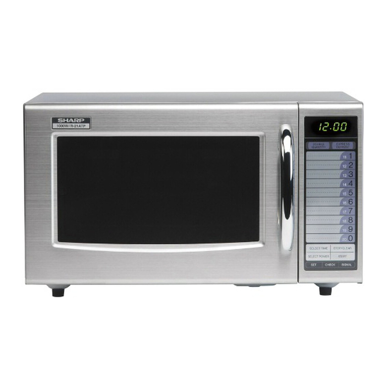
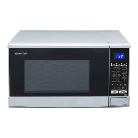
Sharp R-20A1SVN User manual

CHAPTER 1. BEFORE SERVICING
CHAPTER 2. WARNING TO SERVICE PERSONNEL
CHAPTER 3. PRODUCT SPECIFICATIONS
CHAPTER 4. APPEARANCE VIEW
CHAPTER 5. OPERATION SEQUENCE
CHAPTER 6. FUNCTION OF IMPORTANT COMPO-
NENTS
CHAPTER 7. TROUBLESHOOTING GUIDE
CHAPTER 8. TEST PROCEDURES
CHAPTER 9. TOUCH CONTROL PANEL ASSEMBLY
CHAPTER 10. COMPONENT REPLACEMENT AND
ADJUSTMENT PROCEDURE
CHAPTER 11. MICROWAVE MEASUREMENT
CHAPTER 12. CIRCUIT DIAGRAMS
Parts List
SERVICE MANUAL
R-20A1(S)VN
CONTENTS
SHARP CORPORATION This document has been published to be used
for after sales service only.
The contents are subject to change without notice.
S8313R20APVNS
MICROWAVE OVEN
R-20A1(S)VN
R-21A1(S)VN
MODELS
In the interest of user-safety the oven should be restored to its
original condition and only parts identical to tho
should be used.

CONTENTS
CHAPTER 1. BEFORE SERVICING
[1] GENERAL IMPORTANT INFORMATION................1-1
[2] CAUTION MICROWAVE RADIATION .....................1-1
[3] WARNING .....................................................................1-1
CHAPTER 2. WARNING TO SERVICE PERSONNEL
CHAPTER 3. PRODUCT SPECIFICATIONS
CHAPTER 4. APPEARANCE VIEW
[1] OVEN ..............................................................................4-1
[2] TOUCH CONTROL PANEL.........................................4-1
CHAPTER 5. OPERATION SEQUENCE
[1] OFF CONDITION .........................................................5-1
[2] MICROWAVE COOKING CONDITION ...................5-1
[3] POWER OUTPUT REDUCTION..............................5-1
CHAPTER 6. FUNCTION OF IMPORTANT COMPO-
NENTS
[1] DOOR OPEN MECHANISM.....................................6-1
[2] MONITORED LATCH SWITCH AND
LATCH SWITCH............................................................6-1
[3] MONITOR SWITCH .....................................................6-1
[4] FUSE T6.3A.................................................................6-1
[5] HIGH VOLTAGE FUSE .................................................6-1
[6] TEMPERATURE FUSE 150C (OVEN).......................6-1
[7] TURNTABLE MOTOR................................................6-1
[8] FAN MOTOR .................................................................6-1
[9] TIMER MOTOR..............................................................6-1
CHAPTER 7. TROUBLESHOOTING GUIDE
[1] FOREWORD..................................................................7-1
[2] CHART............................................................................7-1
CHAPTER 8. TEST PROCEDURES
[1] Procedure A: MAGNETRON (MG) TEST...............8-1
[2] Procedure B: HIGH VOLTAGE TRANS-
FORMER TEST..............................................................8-2
[3] Procedure C: HIGH VOLTAGE RECTIFI-
ER TEST..........................................................................8-2
[4] Procedure D: HIGH VOLTAGE CAPACI-
TOR TEST.......................................................................8-2
[5] Procedure E: SWITCH TEST .....................................8-2
[6] Procedure F: TEMPERATURE FUSE
TEST ...............................................................................8-3
[7] Procedure G: MOTOR WINDING TEST.................8-3
[8] Procedure H: FUSE T6.3A ........................................8-3
[9] Procedure I: HIGH VOLTAGE FUSE TEST ..............8-3
[10] Procedure J: TIMER MOTOR TEST.........................8-3
CHAPTER 10. COMPONENT REPLACEMENT AND
ADJUSTMENT PROCEDURE
[1] BEFORE OPERATING ................................................... 10-1
[2] OUTER CASE REMOVAL ............................................. 10-1
[3] HIGH VOLTAGE TRANSFORMER RE-
MOVAL ........................................................................... 10-2
[4] HIGH VOLTAGE RECTIFIER ASSEMBLY,
HIGH VOLTAGE FUSE AND HIGH VOLT-
AGE CAPACITOR REMOVAL.................................... 10-2
[5] MAGNETRON REMOVAL .......................................... 10-2
[6] POSITIVE LOCK CONNECTOR (NO-
CASE TYPE) REMOVAL ............................................. 10-2
[7] TURNTABLE MOTOR REMOVAL............................. 10-3
[8] COOLING FAN MOTOR REMOVAL........................ 10-3
[9] POWER SUPPLY CORD REPLACE-
MENT.............................................................................. 10-4
[10] CONTROL PANEL ASSEMBLY REMOV-
AL ................................................................................... 10-4
[11] MONITORED LATCH SWITCH, LATCH
SWITCH AND MONITOR SWITCH RE-
MOVAL .......................................................................... 10-4
[12] MONITORED LATCH SWITCH, LATCH
SWITCH AND MONITOR SWITCH AD-
JUSTMENT................................................................... 10-4
[13] DOOR REPLACEMENT.............................................. 10-5
CHAPTER 11. MICROWAVE MEASUREMENT
CHAPTER 12. CIRCUIT DIAGRAMS
[1] Oven Schematic........................................................ 12-1
[2] Pictorial Diagram(Figure S-1) .............................. 12-2
Parts List
R-20A1(S)VN
R-20A1(S)VN
1 – 1
R218L(W)
CHAPTER 1. BEFORE SERVICING
[1] GENERAL IMPORTANT INFORMATION
This Manual has been prepared to provide Sharp Corp.Service engineers with Operation and Service Information.
isfactory customer ser-
vice.
[2] CAUTION MICROWAVE RADIATION
DO NOT BECOME EXPOSED TO RADIATION FROM THE MICROWAVE GENERATOR OR OTHER PARTS CON-
DUCTING MICROWAVE ENERGY.
Service engineers should not be exposed to the microwave energy which may radiate from the magnetron or other
microwave generating devices if it is improperly used or connected. All input and output microwave connections,
ts must be secured. Never operate the device without a microwave energy absorbing
load attached. Never look into an open wave guide or antenna while the device is energized.
[3] WARNING
Never operate the oven until the following points are ensured.
(A) The door is tightly closed.
(B) The door brackets and hinges are not defective.
(C) The door packing is not damaged.
(D) The door is not deformed or warped.
(E) There is not any other visible damage with the oven.
Servicing and repair work must be carried out only by trained service engineers.
All the parts marked " " on parts list are used at voltages more than 250V.
Removal of the outer wrap gives access to potentials above 250V.
All the parts marked "*" on parts list may cause undue microwave exposure, by themselves, or when they are damaged,
loosened or removed.
WARNING: THIS APPLIANCE MUST BE EARTHED
IMPORTANT
THE WIRES IN THIS MAINS LEAD ARE COLOURED IN ACCORDANCE WITH THE FOLLOWING CODE:
GREEN-AND-YELLOW --------------EARTH
BLUE -----------------------------------NEUTRAL
BROWN ---------------------------------------LIVE

R-20A1(S)VN
2 – 1
R218L(W)
CHAPTER 2. WARNING TO SERVICE PERSONNEL
Microwave ovens contain circuitry capable of producing very high voltage and current, contact with any part of the high voltage circuit will result in
ltage harness.
REMEMBER TO CHECK 3D
1) Disconnect the supply.
2) Door opened, and wedged open.
3) Discharge the high voltage capacitor.
WARNING: AGAINST THE CHARGE OF THE HIGH-VOLTAGE
CAPACITOR
The high-voltage capacitor remains charged about 60 sec-
onds and then short-circuit the connection of the high-
voltage capacitor (that is, of the connecting lead of the
an insulated screwdriver.
out
with the supply disconnected. It may, in some cases, be necessary to
connect the supply after the outer case has been removed, in this
event carry out 3D checks and then disconnect the leads to the pri-
mary of the power transformer. Ensure that these leads remain iso-
lated from other components and the oven chassis. (Use insulation
tape if necessary.) When the testing is completed, carry out 3D checks
and reconnect the leads to the primary of the power transformer.
REMEMBER TO CHECK 4R
1) Reconnect all leads removed from components during testing.
2) Replace the outer case (cabinet).
3) Reconnect the supply.
4) Run the oven. Check all functions.
Microwave ovens should not be run empty. To test for the presence of
microwave energy within a cavity, place a cup of cold water on the
oven turntable, close the door and set the power level to HIGH
(100%). And set the microwave timer for two (2) minutes. When the
two minutes has elapsed (timer at zero) carefully check that the water
is now hot. If the water remains cold, carry out 3D checks and re-
examine the connections to the component being tested.
When all service work is completed and the oven is fully assembled, the microwave power output should be checked and microwave leakage test
should be carried out.

Depth 380 mm
R-20A1(S)VN
3 – 1
R218L(W)
CHAPTER 3. PRODUCT SPECIFICATIONS
NOITPIRCSEDMET
Power Requirements
220 Volts
50 Hertz
Single phase, 3 wire earthed
Power Consumption 1.25 kW
Power Output 800 watts nominal of RF microwave energy (measured by method of IEC 60705)
Operating frequency 2450 MHz
Outside Dimensions
Width 460 mm
Height 275 mm including foot
Cooking Cavity Dimensions
Width 319 mm NOTE: Internal capacity is calculated by measuring maximum width, depth and height.
Height 211 mm Actual capacity for holding food is less.
Depth 336 mm
Turntable diameter 272 mm
Control Complement
Timer (0 - 30 minutes)
Microwave Power for Variable Cooking
Repetition Rate;
HIGH ................................................................ Full power throughout the cooking time
MEDIUM HIGH ................................................................. approx. 70% of FULL Power
MEDIUM ......................................................................... approx. 50% of FULL Power
MEDIUM LOW ................................................................. approx. 30% of FULL Power
LOW ................................................................................ approx. 10% of FULL Power
Set Weight (Approx.) 12 kg

R-20A1(S)VN
4–1
R218L(W)
CHAPTER 4. APPEARANCE VIEW
[1] OVEN
1. Ventilation openings
2. Oven lamp
3. Door hinges
4. Door safety latches
5. See through door
6. Door seals sealing surfaces
7. Coupling
8. Control panel
9. Waveguide cover
10. Power supply cord
11. Turntable
12. Roller stay
13. Outer case cabinet
14. Door open button
[2] TOUCH CONTROL PANEL
11
12
1
10
13
2
7
38
14
44
5
6
9
VARIABLE COOKING CONTROL
There are five power levels. The approxi-
mate percentage of microwave power for
each setting is:
%01HGIH
MED HIGH 70%
%05DEM
MED LOW (DEFROST) 30%
%01WOL
MEAT DEFROST
TIMER (0-30minutes)
Turn to set cooking time or weight of de-
frost food.
0

R-20A1(S)VN
5 – 1
R218L(W)
CHAPTER 5. OPERATION SEQUENCE
[1] OFF CONDITION
1. When the timer knob is at “0”, the oven is OFF condition.
2. Closing the oven door activates the monitored latch switch and the
latch switch.
IMPORTANT
When the oven door is closed, the contacts (COM-NC) of the monitor
switch must be open.
When the microwave oven is plugged in a wall outlet, rated voltage is
supplied to the fuse holder assembly.
Figure O-1 on page 12-1
[2] MICROWAVE COOKING CONDITION
1. HIGH COOKING
Set the cooking control to HIGH and then set the timer.
Function sequence
Figure O-2 on page 12-1
1. Following components are energized.
High voltage capacitor High voltage fuse
Turntable motor Timer motor Fan motor
2. Rated voltage is supplied to the primary winding of the high voltage
transformer. The voltage is converted to about 3.3 volts A.C. output
volts A.C. on the secondary winding.
ment and the high voltage (2000 volts) is sent to the voltage dou-
bling circuit, where it is doubled to negative voltage of
approximately 4000 volts D.C..
4. The 2450 MHz microwave energy produced in the magnetron gen-
erates a wave length of 12.24 cm. This energy is channelled
through the waveguide (transport channel) into the oven cavity,
where the food is placed to be cooked.
5. When the cooking time is up, the timer returns to “0”, the bell rings
and the contacts of the timer switch are opened. The following
High voltage capacitor High voltage fuse
Turntable motor Timer motor Fan motor
Magnetron Oven lamp
6. When the oven door is opened during a cook cycle, the switches
come to the following position and they are common to the other
cooking conditions too.
The circuits to the high voltage transformer, turntable motor, timer
contacts (COM-NO) of the monitored latch switch and latch switch
are made open.
The timer stops to indicate how much cooking time remains.
7. MONITOR SWITCH CIRCUIT
The monitor switch is mechanically controlled by oven door, and
monitors the operation of the monitored latch switch and the relay
RY1.
1) When the oven door is opened during or after the cycle of a
cooking program, the monitored latch switch and latch switch
(COM-NC) of the monitor switch can be closed.
2) When the oven door is closed, the contacts (COM-NC) of the
(COM-NO) of the monitored latch switch and the latch switch
are closed.
3) When the oven door is opened and the contacts (COM-NO) of
the monitored latch switch and contacts of the timer switch and
the contact of the relay RY1 remain closed, the fuse T6.3A will
blow, because the monitor switch is closed and a short circuit is
caused.
2. MEDIUM HIGH, MEDIUM, MEDIUM LOW, LOW
COOKING
When the microwave oven is preset for variable cooking power, rated
voltage is supplied to the high voltage transformer intermittently within
a 32-second time base through the relay contact which is coupled with
the current-limiting relay. The following levels of microwave power are
given.
SETTING;
NOTE: The ON/OFF time ratio does not exactly correspond to the
percentage of microwave power, because approx. 3 seconds
[3] POWER OUTPUT REDUCTION
20 minutes the power level will automatically adjust itself to 70%
power to avoid overcooking.
2. If the oven is operated for more than 90 minutes continuously (at
any power levels), the relay RY1 opens. And the circuit to the high
CONNECTED COMPONENTS RELAY
High voltage transforme RY1
CONDITION
SWITCH CONTACT
DURING
COOKING
DOOR OPEN
(NO COOKING)
Monitored latch
switch COM-NO Closed Open
Latch switch COM-NO Closed Open
Monitor switch COM-NC Open Closed
HIGH
32 sec. ON
MEDIUM HIGH
Approx. 70%
100%
24 sec. ON 8 sec. OFF
14 sec. OFF
20 sec. OFF
26 sec. OFF
%05.xorppAMUIDEM
18 sec. ON
MEDIUM LOW
Approx. 30%
12 sec. ON
%01.xorppAWOL
6sec.ON

R-20A1(S)VN
6 – 1
R218L(W)
CHAPTER 6. FUNCTION OF IMPORTANT COMPONENTS
[1] DOOR OPEN MECHANISM
The door is opened by pushing the open button on the control panel,
refer to the Figure D-1.
When the open button is pushed, the open button pushes up the
switch lever, and then the switch lever pushes up the latch head. The
latch heads are moved upward and released from latch hook. Now the
door will open.
Figure D-1. Door Open Mechanism
[2] MONITORED LATCH SWITCH AND
LATCH SWITCH
1. When the oven door is closed, the contacts (COM-NO) must be
closed.
[3] MONITOR SWITCH
1. When the oven door is closed, the contacts (COM-NC) must be
opened.
2. When the oven door is opened, the contacts (COM-NC) must be
closed.
3. If the oven door is opened and the contacts (COM-NO) of the mon-
itored latch switch, the contacts of the relay RY1 and the timer
switch fail to open, the fuse T6.3A blows immediately after closing
the contacts (COM-NC) of the monitor switch.
CAUTION: BEFORE REPLACING A BLOWN FUSE TEST THE MON-
ITORED LATCH SWITCH, RELAY RY1, TIMER SWITCH
AND MONITOR SWITCH FOR PROPER OPERATION.
(REFER TO CHAPTER “TEST PROCEDURE”.)
[4] FUSE T6.3A
1. The fuse T6.3A blows when the contacts (COM-NO) of the moni-
tored latch switch, the contacts of the relay RY1 and the timer
switch remain closed with the oven door open and when the con-
tacts (COM-NC) of the monitor switch are close.
2. If the wire harness or electrical components are short-circuited, the
[5] HIGH VOLTAGE FUSE
netron is shorted.
[6] TEMPERATURE FUSE 150C (OVEN)
The temperature fuse located on the top of the oven cavity is designed
by either error in cook time or defect in the control unit, the tempera-
ture fuse will open. Under normal operation, the temperature fuse
remains closed. However, when abnormally high temperatures are
reached within the oven cavity, the temperature fuse will open at
150 C, causing the oven to shut down. The defective temperature fuse
must be replaced with a new one.
[7] TURNTABLE MOTOR
The turntable motor drives the turntable roller assembly to rotate the
turntable.
[8] FAN MOTOR
The fan motor drives a blade which draws external cool air. This cool
air is directed through the air vanes surrounding the magnetron and
cools the magnetron. This air is channelled through the oven cavity to
exhausted through the exhausting air vents at the oven cavity.
[9] TIMER MOTOR
Timer switch
1. When the timer switch is at “0” position, the switch of the timer is
opened.
2. When the timer is turned clockwise from “0” position, the switch of
the timer is closed.
Latch Heads
Latch Hook
Door
Monitored
Latch Switch
Monitor Switch
Switch Lever Latch Switch

R-20A1(S)VN
7 – 1
R218L(W)
CHAPTER 7. TROUBLESHOOTING GUIDE
[1] FOREWORD
When troubleshooting the microwave oven, it is helpful to follow the
Sequence of Operation in performing the checks. Many of the possible
tests are given a procedure letter which will be found in the “Test Pro-
cedure” section.
IMPORTANT:
If the oven becomes inoper ative because of a blown fuse T6.3A in the
monitored latch switch - relay RY1 - timer switch - monitor switch cir-
cuit, check the monitored latch switch, relay RY1, timer switch and
monitor switch before replacing the fuse T6.3A.
[2] CHART
MAGNETRON
HIGH VOLTAGE TRANSFORMER
H.V. RECTIFIER ASSEMBLY
HIGH VOLTAGE WIRE
HIGH VOLTAGE CAPACITOR
MONITORED. LATCH SWITCH
LACTCH SWITCH
TEMPERATURE FUSE
MONITOR SWITCH
TIMER MOTOR
TIMER SWITCH
FAN MOTOR
TURNTABLE MOTOR
FUSE T6.3A
RELAY (RY-1)
FOIL PATERN ON P.W.B.
POWER SUPPLY CORD
SHORTED WIRE HARNESS
OPENED WIRE HARNESS
OVEN LAMP
WALL OUTLET
MISADJUSTMENT SWITCH
HOME FUSE OR BREAKER
BLOCKED COOLING FAN
BLOCKED VENTILATION
H.V. FUSE
OFF
CONDITION
PROBLEM
CONDITION
POSSIBLE CAUSE
AND
DEFECTIVE PARTS
TEST PROCEDURE
ON
CONDITION
ABC
CK
DEEIJFEMHGGJL
RE CK CK RE CK CK CK CK CK
Home fuse blows when pow-
ersupply cord is plugged into
wall outlet.
FUSE T6.3A blows when
power supply cord is plug-
ged into wall outlet.
Oven does not start when
the timer is set
Oven lamp does not light
(Other function is normal.)
Fan motor does not operate.
(Other function is normal.)
Turntable motor does not
operate. (Other function is
normal.)
Oven or any electrical parts
does not stop.
Oven seems to be operating
but little or no heat is pro-
duced in oven load. (Micro-
wave power level is set at
HIGH)
Oven does not seems to be
operating properly when
MEDHIGH,MED,MED
LOW or LOW is set. (Oven
operates properly at HIGH.)
Oven goes into cook cycle
but shuts down before end
of cooking cycle.

R-20A1(S)VN
8 – 1
R218L(W)
CHAPTER 8. TEST PROCEDURES
[1] Procedure A: MAGNETRON (MG) TEST
NEVER TOUCH ANY PART IN THE CIRCUIT WITH YOUR HAND OR AN INSULATED TOOL WHILE THE OVEN IS IN OPERATION.
CARRY OUT 3D CHECKS.
r should show a
reading of less than 1 ohm.
he magnetron
on should be replaced.
MICROWAVE OUTPUT POWER (1 litre water load)
icrowave output power
from the magnetron can be measured by IEC test procedure, i.e. it can be measured by using water load how much it can be absorbed by the water
load. To measure the microwave output power in the microwave oven, the relation of calorie and watt is used. When P(W) heating works for t(sec-
ond), approximately P x t/4.187 calorie is generated. On the other hand, if the temperature of the water with V(ml) rises T ( C) during this microwave
heating period, the calorie of the water is v x T.
Measuring condition:
1) Container
The water container must be a cylindrical borosilicate glass vessel having a maximum material thickness of 3 mm and an outside diameter of
approximately 190 mm.
2) Temperature of the oven and vessel
The oven and the empty vessel are at ambient temperature prior to the start of the test.
3) Temperature of the water
The initial temperature of the water is (10 1) C
t temperature is
5C.
5) Select stirring devices and measuring instruments in order to minimize addition or removal of heat.
6) The graduation of the thermometer must be scaled by 0.1 C at minimum and an accurate thermometer.
7) The water load must be (1000 5) g.
NOTE
Measuring method:
1) 1.Measure the initial temperature of the water before the water is added to the vessel.
(Example: The initial temperature T1 = 11 C)
2) Add the 1 litre water to the vessel.
3) Place the load on the centre of the shelf.
4) Operate the microwave oven at 100% for the temperature of the water rises by a value T of 10 C.
5) Stir the water to equalize temperature throughout the vessel.
C)
7) Calculate the microwave power output P in watts from above formula.
JUDGEMENT: The measured output power should be at least 15 % of the rated output power.
CAUTION: 1 C CORRESPONDS TO 80 WATTS. REPEAT MEASUREMENT IF THE POWER IS INSUFFICIENT.
The formula is as follows;
P x t / 4.187 = V x T+ 0.55 x mc (T2-T0)/4.187 P (W) = 4.187 x V x T / t + 0.55 x mc (T2-T0)/t
Our condition for water load is as follows:
Room temperature (T0) ......................... around 20°C Power supply ........................... VoltageRated voltage
Water load ...............................................................1000 g Initial temperature (T1) .................................... 10±1°C
Heating time .......................................................... 52 sec. Mass of container (mc) ...................................... 330 g
T2 ........................................................ Final Temperature T = T2 - T1 P= 80 x T + 0.55 x mc (T2-T0)/52
Room temperature ................................................................... To = 21 C
Initial temperature ..................................................................... T1 = 11 C
Temperature after (52 + 3) = 55 sec ...................................... T2 = 21 C
C
Measured output power
The equation is "P = 80 x T" .................... P = 80 x 10 C = 800 Watts

R-20A1(S)VN
8 – 2
[2] Procedure B: HIGH VOLTAGE TRANSFORMER TEST
1. CARRY OUT 3D CHECKS.
nections from the
rest of the HV circuitry. Using an ohmmeter, set on a low range, it is possible to check the continuity of all three winding. The following readings
should be obtained:
a.Primary winding -------------------- 2.8 ohms approximately
b.Secondary winding --------------- 204 ohms approximately
c.Filament winding ------------------------------ less than 1 ohm
If the readings obtained are not stated as above, then the high voltage transformer is probably faulty and should be replaced.
3. Also, the high voltage transformer has the thermal cut-out in the primary coil. The thermal cut-out will open when the temperature of the thermal
cut-out in the primary coil reaches approximately 150 C. The thermal cut-out resets automatically at 130 C. If an ohmmeter indicates an open cir-
cuit under normal condition, replace the high voltage transformer because the primary coil (thermal cut-out) has opened. An open primary coil
former, especially the
ventilation opening.
4. CARRY OUT 4R CHECKS.
[3] Procedure C: HIGH VOLTAGE RECTIFIER TEST
CARRY OUT 3D CHECKS.
o its highest range.
d note this second
in the other direction.
CARRY OUT 4R CHECKS.
NOTE: FOR MEASUREMENT OF THE RESISTANCE OF THE RECTIFIER, THE BATTERIES OF THE MEASURING INSTRUMENT MUST HAVE
A VOLTAGE AT LEAST 6 VOLTS, BECAUSE OTHERWISE AN INFINITE RESISTANCE MIGHT BE SHOWN IN BOTH DIRECTION.
[4] Procedure D: HIGH VOLTAGE CAPACITOR TEST
CARRY OUT 3D CHECKS.
1. Isolate the high voltage capacitor from the circuit.
2. Continuity check must be carried out with measuring instrument which is set to the highest resistance range.
3. A normal capacitor shows continuity for a short time (kick) and then a resistance of about 10M after it has been charged.
4. A short-circuited capacitor shows continuity all the time.
5. An open capacitor constantly shows a resistance about 10 M because of its internal 10M resistance.
If incorrect reading are obtained, the high voltage capacitor must be replaced.
CARRY OUT 4R CHECKS.
[5] Procedure E: SWITCH TEST
CARRY OUT 3D CHECKS.
Isolate the switch to be tested and using an ohmmeter check between the terminals as described in the following table.
WARNING: High voltages and large currents are present at the secondary winding and filament winding of the power transformer. It is
very dangerous to work near this part when the oven is on. NEVER make any voltage measurements of the high-voltage cir-
cuits, including the magnetron filament.
Table: Terminal Connection of Switch
Plunger Operation COM to NO COM to NC COM; Common terminal
Released Open circuit Short circuit NO; Normally open terminal
Depressed Short circuit Open circuit. NC; Normally close terminal
1000g
1000g1000g
T1 C T2 C

R-20A1(S)VN
8 – 3
If incorrect readings are obtained, make the necessary switch adjustment or replace the switch.
CARRY OUT 4R CHECKS.
[6] Procedure F: TEMPERATURE FUSE TEST
CARRY OUT 3D CHECKS.
Disconnect the leads from the terminals of the temperature fuse. Then using an ohmmeter, make a continuity test across the two terminals as
described in the below.
If incorrect readings are obtained, replace the temperature fuse.
g produced by
improper setting of the cooking time or failure of the control panel.
CARRY OUT 4R CHECKS.
[7] Procedure G: MOTOR WINDING TEST
CARRY OUT 3D CHECKS.
Disconnect the leads from the motor. Using an ohmmeter, check the resistance between the two terminals as described in the table below.
If incorrect readings are obtained, replace the motor.
CARRY OUT 4R CHECKS.
[8] Procedure H: FUSE T6.3A
CARRY OUT 3D CHECKS.
If the fuse T6.3A is blown when the door is opened, check the monitored latch switch, relay (RY1), timer switch and monitor switch.
If the fuse T6.3A is blown by incorrect door switching replace the defective switch(es) and the fuse T6.3A.
If the fuse T6.3A is blown, there is a shorts or grounds in electrical parts or wire harness. Check them and replace the defective parts or repair the
wire harness.
CARRY OUT 4R CHECKS.
CAUTION: ONLY REPLACE FUSE T6.3A WITH THE CORRECT VALUE REPLACEMENT.
[9] Procedure I: HIGH VOLTAGE FUSE TEST
CARRY OUT 3D CHECKS.
Check them and replace the defective parts and the high voltage fuse.
CARRY OUT 4R CHECKS.
CAUTION: ONLY REPLACE HIGH VOLTAGE FUSE WITH THE CORRECT VALUE REPLACEMENT.
[10] Procedure J: TIMER MOTOR TEST
CARRY OUT 3D CHECKS before any of the following timer tests.
1. TIMER SWITCH- CONTACTS
Disconnect the leads from terminals described at fo llowing table. Connect an ohmmeter across terminals
described at following table.
Advance the timer and check that a short circuit reading is obtained on the meter.
Turn the timer back to the zero (0) position and check that an open circuit reading is obtained on the meter. If these readings are not obtained then
replace the timer.
Table: Temperature Fuse Test
Parts Name Temperature of “ON” condition
(closed circuit).
Temperature of “OFF” condition
(open circuit).
Indication of ohmmeter (When room
temperature is approx. 20 C.)
Temperature fuse 150 C This is not resetable type. Above 150 tiucricdesolCC
Table: Resistance of Motor
Motors Resistance
Fan motor Approximately 250
Turntable motor Approximately 14.7 k
Disconnecting and checking terminals 1 and 2
M
4
2
3
1

R-20A1(S)VN
8 – 4
2. TIMER - MOTOR
Disconnect the leads from terminals described at following table. Connect an ohmmeter across the timer motor winding, terminals are described at
following table, and check that a reading of resistance described at following table is indicated.
If this reading is not obtained then the timer is probably defective and should be replaced.
CARRY OUT 4R CHECKS.
Disconnecting and checking terminals
Resistance of motor winding
1 and 2
approximately 22.2 k ohms

R-20A1(S)VN
10 – 1
R218L(W)
CHAPTER 10. COMPONENT REPLACEMENT AND ADJUSTMENT PROCE-
DURE
[1] BEFORE OPERATING
Microwave ovens contain circuitry capable of producing very high voltage and current, contact with following parts may result in severe, possibly fatal,
electric shock.
(Example)
WARNING: Avoid possible exposure to microwave energy. Please follow the instructions below before operating
the oven.
1) Disconnect the power supply cord.
oven door is unlatched. (Hold the door in a closed position with one
hand, then push the door open button with the other, this causes
the latch leads to rise, it is then possible to hear a “click” as the
door switches operate.)
3) Visually check the door and cavity face plate for damage (dents,
cracks, signs of arcing etc.).
Carry out any remedial work that is necessary before operating the
oven.
Do not operate the oven if any of the following conditions exist;
2) Door hinge, support or latch hook is damaged.
3) The door gasket or seal is damaged.
4) The door is bent or warped.
5) There are defective parts in the door interlock system.
6) There are defective parts in the microwave generating and trans-
mission assembly.
7) There is visible damage to the oven.
Do not operate the oven:
1) Without the RF gasket (Magnetron).
2) If the wave guide or oven cavity are not intact.
3) If the door is not closed.
To prevent an electric shock, take the following manners.
1. Before wiring,
1) Disconnect the power supply cord.
2) Open the door and block it open.
3) Discharge the high voltage capacitor and wait for 60 seconds.
2. Don't let the wire leads touch to the following parts;
1) High voltage parts:
Magnetron, High voltage transformer, High voltage capacitor,
y.
2) Hot parts:
Oven lamp, Magnetron, High voltage transformer and Oven
cavity.
3) Sharp edge:
plate.
4) Movable parts (to prevent a fault)
Fan blade, Fan motor, Turntable motor and Switch.
3. Do not catch the wire leads in the outer case cabinet.
4. Insert the positive lock connector certainly until its pin is locked and
are pulled.
5. To prevent an error function, connect the wire leads correctly, refer-
ring to the Pictorial Diagram.
Please refer to ‘OVEN PARTS, CABINET PARTS, CONTROL PANEL PARTS, DOOR PARTS’, when carrying out any of the following removal proce-
dures:
[2] OUTER CASE REMOVAL
To remove the outer case, procedure as follows.
1. Disconnect the oven from power supply.
2. Open the oven door and wedge it open.
3. Remove the two (2) screws from right side of the outer case cabi-
net.
om rear and along the side edge of
case.
5. Slide the entire case back about 3cm to free it from retaining clips
on the cavity face plate.
6. Lift the entire case from the oven.
7. Discharge the H.V. capacitor before carrying out any further work.
8. Do not operate the oven with the outer case removed.
NOTE: Step 1, 2 and 7 form the basis of the 3D checks.
CAUTION: DISCONNECT OVEN FROM POWER SUPPLY BEFORE
REMOVING OUTER CASE.
WARNING AGAINST HIGH VOLTAGE:
WARNING FOR WIRING
REMEMBER TO CHECK 3D
1) Disconnect the supply. 3)Discharge high voltage capacitor.
2)Door opened, and wedged open.

R-20A1(S)VN
10 – 2
[3] HIGH VOLTAGE TRANSFORMER REMOVAL
1. CARRY OUT 3D CHECKS.
2. Disconnect the wire leads (main wire harness and H.V. fuse) from
high voltage transformer.
magnetron.
high voltage capacitor.
5. Remove the two (2) screws holding the transformer to bottom plate
from below.
6. Remove the two (2) screws holding the transformer to bottom plate
from above.
7. Remove the transformer.
[4] HIGH VOLTAGE RECTIFIER ASSEMBLY, HIGH VOLTAGE FUSE AND HIGH VOLTAGE
CAPACITOR REMOVAL
To remove the components, proceed as follows.
1. CARRY OUT 3D CHECKS.
2. Disconnect the H.V. fuse from the high voltage transformer.
magnetron.
the H.V. capacitor.
5. Remove one (1) screw holding capacitor holder to the oven cavity
back plate.
6. Remove one (1) screw holding earth side terminal of high voltage
assembly from high voltage capacitor.
8. Disconnect the H.V. fuse from the high voltage capacitor.
free.
CAUTION: WHEN REPLACING HIGH VOLTAGE RECTIFIER
ASSEMBLY, ENSURE THAT THE CATHODE (EARTH)
CONNECTION IS SECURELY FIXED TO THE CAPACI-
TOR HOLDER WITH AN EARTHING SCREW.
CAUTION: DO NOT REPLACE ONLY HIGH VOLTAGE RECTIFIER.
WHEN REPLACING IT, REPLACE HIGH VOLTAGE REC-
TIFIER ASSEMBLY.
[5] MAGNETRON REMOVAL
1. REMOVAL
1. CARRY OUT 3D CHECKS.
2. Disconnect the wire leads from the magnetron.
3. Remove the two (2) screws holding the air duct to the oven cavity.
4. Release the air duct from the oven cavity.
5. Carefully remove the four (4) screws holding the magnetron to the
6. Lift up magnetron with care so that the magnetron antenna is not
hit by any metal object around antenna.
7. Now, the magnetron is free.
2. REINSTALLATION
screws.
2. Reinstall the air duct to the oven cavity with the two (2) screws.
3. Reconnect the wire leads to the magnetron. Refer to “PICTORIAL
DIAGRAM”.
4. Reinstall the outer case and check that the oven is operating prop-
erly.
CAUTION: WHEN REPLACING THE MAGNETRON, BE SURE THE
R.F. GASKET IS IN PLACE AND THE MAGNETRON
MOUNTING SCREWS ARE TIGHTENED SECURELY.
[6] POSITIVE LOCK CONNECTOR (NO-CASE TYPE) REMOVAL
1. CARRY OUT 3D CHECKS.
2. Push the lever of positive lock connector.
3. Pull down on the positive lock connector.
CAUTION: WHEN CONNECTING THE POSITIVE LOCK CONNEC-
TORS TO THE TERMINALS, CONNECT THE POSITIVE
LOCK®
®
®
®
SO THAT THE LEVER FACES YOU.
Figure C-1. Positive lock ®connector
Terminal
Push
Pull down
1
2
Lever
Positive lock¨
connector

R-20A1(S)VN
10 – 3
[7] TURNTABLE MOTOR REMOVAL
1. REMOVAL
1. Disconnect the power supply cord.
2. Remove turntable and turntable support from oven cavity.
3. Lay the oven on it's backside. Remove the turntable motor cover by
No sharp edges must be evident after removal of the turntable
motor cover.
5. Disconnect wire leads from turntable motor.
(See “Positive lock connector removal”)
6. Remove one (1) screw holding turntable motor to oven cavity.
7. Remove the TTM packing from the turntable motor.
8. Now, the turntable motor is free.
2. REINSTALL
1. Re-install the TTM packing to the turntable motor.
2. Re-install the turntable motor with the TTM packing with the single
(1) screw to the oven cavity bottom plate.
3. Re-connect the wire leads to the turntable motor.
4. Insert the tab of the turntable motor cover into the hole of the bot-
tom plate.
5. Re-install the turntable motor cover to the bottom plate with one (1)
screw.
Figure C-2. TTM packing Installation
[8] COOLING FAN MOTOR REMOVAL
1. REMOVAL
1. CARRY OUT 3D CHECKS.
2. Disconnect the wire leads from the fan motor.
3. Remove the two (2) screws holding the fan motor to the oven cavity
back plate.
4. Remove the fan blade from the fan motor shaft according to the fol-
lowing procedure.
5. Hold the edge of the rotor of the fan motor by using a pair of groove
joint pliers.
CAUTION: MAKE SURE THAT ANY PIECES DO NOT ENTER THE
GAP BETWEEN THE ROTOR AND THE STATOR OF THE
FAN MOTOR. BECAUSE THE ROTOR IS EASY TO BE
SHAVEN BY PLIERS AND METAL PIECES MAY BE PRO-
DUCED.
DO NOT TOUCH THE PLIERS TO THE COIL OF THE
FAN MOTOR BECAUSE THE COIL MAY BE CUT OR
INJURED.
DO NOT DISFIGURE THE BRACKET BY TOUCHING
WITH THE PLIERS.
6. Remove the fan blade from the shaft of the fan motor by pulling and
rotating the fan blade with your hand.
7. Now, the fan blade will be free.
CAUTION: DO NOT RE-USE THE REMOVED FAN BLADE
BECAUSE THE HOLE (FOR SHAFT) MAY BE LARGER
THAN NORMAL.
8. Now, the fan motor is free.
2. INSTALLATION
1. Install the fan blade to the fan motor shaft according to the following
procedure.
2. Hold the center of the bracket which supports the shaft of the fan
3. Apply the screw lock tight into the hole (for shaft) of the fan blade.
4. Install the fan blade to the shaft of fan motor by pushing the fan
blade with a small, light weight, ball peen hammer or rubber mallet.
CAUTION: DO NOT HIT THE FAN BLADE STRONGLY WHEN
INSTALLED BECAUSE THE BRACKET MAY BE TRANS-
FORMED.
MAKE SURE THAT THE FAN BLADE ROTATES
SMOOTH AFTER INSTALLED.
MAKE SURE THAT THE AXIS OF THE SHAFT IS NOT
SLANTED.
5. Install the fan motor assembly to the oven cavity back plate with
two (2) screws.
6. Connect the wire leads to the magnetron and fan motor, referring to
the pictorial diagram.
TTM packing
Turntable motor
Gap
Rotor
Bracket
Stator
Groove joint pliers
Coil
Shaft
Axis
Stator
Rotor
These are the positions
that should be pinched
with pliers.
Shaft
Table Center of
bracket
Rear View Side View

R-20A1(S)VN
10 – 4
[9] POWER SUPPLY CORD REPLACEMENT
1. REMOVAL
1. CARRY OUT 3D CHECKS.
2. Remove the single (1) screw holding the green/yellow wire to the
oven cavity back plate.
3. Disconnect the leads of the power supply cord from the fuse holder
assembly, referring to the Figure C-3(a).
4. Release the moulding cord stopper of the power supply cord from
the square hole of the oven cavity back plate, referring to the Fig-
ure C-3 (b).
5. Now, the power supply cord is free.
2. REINSTALL
1. Insert the moulding cord stopper of power supply cord into the
square hole of the rear cabinet, referring to the Figure C-3 (b).
2. Install the earth wire lead of power supply cord to the oven cavity
back plate with one (1) screw and tight the screw.
3. Connect the brown and blue wire leads of power supply cord to the
fuse holder assembly correctly, referring to the Pictorial Diagram.
Figure C-3(a) Power Supply Cord Replacement
Figure C-3(b) Power Supply Cord Replacement
[10] CONTROL PANEL ASSEMBLY REMOVAL
1. CARRY OUT 3D CHECKS.
2. Remove the one (1) screw holding the control panel to the front
panel of the oven cavity.
3. Lift up the control panel assembly and release it from the oven cav-
ity.
4. Now, the control panel assembly is free.
[11] MONITORED LATCH SWITCH, LATCH SWITCH AND MONITOR SWITCH REMOVAL
1. REMOVAL
1. CARRY OUT 3D CHECKS.
2. Disconnect wire leads from the switches.
4. Remove the switch lever from the oven cavity.
6. Push outward on the two (2) retaining tabs holding switch in place.
7. Switch is now free.
2. REINSTALL
1. Re-install each switch in its place. The latch/monitor switches are in
the lower position and the monitored latch switch is in the upper
position.
2. Re-connect wire leads to each switch. Refer to pictorial diagram.
4. Install the switch lever to the oven cavity.
5. Make sure that the monitor switch is operating properly and check
continuity of the monitor circuit. Refer to chapter “Test Procedure”
and Adjustment procedure.
[12] MONITORED LATCH SWITCH, LATCH SWITCH AND MONITOR SWITCH ADJUSTMENT
1. Adjustment
1. CARRY OUT 3D CHECKS.
If the monitored latch switch, latch switch and monitor switch do not
operate properly due to a misadjustment, the following adjustment
should be made.
2. Loosen the two (2) screws holding latch hook to the oven cavity
3. With door closed, adjust latch hook by moving it back and forth,
and up and down. In and out play of the door allowed by the upper
and lower position of the latch hook should be less than 0.5mm.
The vertical position of the latch hook should be adjusted so that
the monitored latch switch and latch switch are activated with the
door closed. The horizontal position of the latch hook should be
adjusted so that the plunger of the monitor switch is pressed with
the door closed.
5. Check the operation of all switches. If each switch has not activated
with the door closed, loosen screw and adjust the latch hook posi-
tion.
NL
Power Supply
Cord Oven Cavity
Back Plate
Screw
Green/Yellow
Wire
Brown Wire
Blue
Wire
Fuse holder assembly
WHT
RED
Power Supply
Cord
Oven Cavity
Back Plate
Square
Hole
Moulding
Cord Stopper

R-20A1(S)VN
10 – 5
2. After adjustment, check the following.
1. In and out play of door remains less than 0.5mm when in the
latched position. First check upper position of latch hook, pushing
and pulling upper portion of door toward the oven face. Then check
lower portion of the latch hook, pushing and pulling lower portion of
the door toward the oven face. Both results (play in the door)
should be less than 0.5mm.
2. The monitored latch switch, latch switch interrupt the circuit before
the door can be opened.
3. Monitor switch contacts close when door is opened.
4. Re-install outer case and check for microwave leakage around
door with an approved microwave survey meter. (Refer to Micro-
wave Measurement Procedure.)
Figure C-5. Latch Switch Adjustments
[13] DOOR REPLACEMENT
1. REMOVAL
1. Disconnect the power supply cord.
2. Open the door slightly.
3. Insert a putty knife (thickness of about 0.5mm) into the gap
between the choke cover and corner portion of door panel as
shown in Figure C-5 to free engaging parts.
ure C-5.
5. Release choke cover from door panel.
6. Now choke cover is free.
NOTE: When carrying out any repair to the door, do not bend or
warp the slit choke (tabs on the door panel assembly) to
prevent microwave leakage.
Figure C-5. Door Disassembly
7. Release two (2) pins of door panel from two (2) holes of upper and
lower oven hinges by lifting up.
8. Now, door panel is free from oven cavity.
9. Release door panel from ten (10) tabs of door frame and remove
door frame by sliding the door panel downward.
12.Now, door panel is free.
13.Slide latch head upward and remove it from door frame with releas-
ing latch spring from door frame and latch head.
14.Now, latch head and latch spring are free.
15.Remove door screen from door frame.
16.Now, door screen is free.
2. REINSTALLATION
1. Re-install door screen to door frame.
2. Re-install latch spring to the head. Re-install latch spring to the
door frame. Re-install latch head to the door frame.
5. Catch two (2) pins of door panel on two (2) hole of upper and lower
oven hinges.
6. Re-install choke cover to door panel by pushing.
NOTE: After any service to the door;
1) Make sure that monitored latch switch, latch switch and moni-
tor switch are operating properly. (Refer to chapter “Test Pro-
cedures”.).
2) An approved microwave survey meter should be used to
assure compliance with proper micro-wave radiation emission
limitation standards.
3. After any service, make sure of the following:
1. Door latch heads smoothly catch latch hook through latch holes
and that latch head goes through center of latch hole.
2. Deviation of door alignment from horizontal line of cavity face plate
is to be less than 1.0mm.
3. Door is positioned with its face pressed toward cavity face plate.
4. Check for microwave leakage around door with an approved micro-
wave survey meter. (Refer to Micro-wave Measurement Proce-
dure.)
NOTE: The door on a microwave oven is designed to act as an
electronic seal preventing the leakage of microwave
energy from oven cavity during cook cycle. This function
does not require that door be air-tight, moisture (conden-
sation)-tight or light-tight. Therefore, occasional appear-
ance of moisture, light or sensing of gentle warm air
movement around oven door is not abnormal and do not
of themselves, indicate a leakage of microwave energy
from oven cavity.
Latch Heads
Latch Hook
Door
Monitored
Latch Switch
Monitor Switch
Switch Lever Latch Switch
10
5
4
8
7
9
11
3
2
1
Choke Cover
Door Frame
Putty Knife
6

R-20A1(S)VN
10 – 6
Figure C-6. Door Replacement
4. SEALER FILM
shown in Fig. C-7
Pin
Pin
Upper Oven Hinge
Lower
Oven
Hinge
Lower Oven
Hinge
Choke Cover
Slit Choke
Door
Panel
Sealer film Backing film
Adhesive tape

R-20A1(S)VN
11 – 1
R218L(W)
CHAPTER 11. MICROWAVE MEASUREMENT
After adjustment of door latch switches, monitor switch and door are completed individually or collectively, the following leakage test must be per-
microwave oven.
REQUIREMENT
The safety switch must prevent microwave radiation emission in excess of 5mW/cm2at any point 5cm or more from external surface of the oven.
PREPARATION FOR TESTING
Before beginning the actual test for leakage, proceed as follows;
Important:
Survey instruments that comply with the requirement for instrumentations as prescribed by the performance standard for microwave ovens must
be used for testing.
Recommended instruments are:
NARDA 8100
NARDA 8200
HOLADAY HI 1500
SIMPSON 380M
2. Place the oven tray into the oven cavity.
3. Place the load of 275 15ml of water initially at 20 5C in the centre of the oven tray. The water container should be a low form of 600 ml beaker
with inside diameter of approx. 8.5cm and made of an electrically non-conductive material such as glass or plastic.
The placing of this standard load in the oven is important not only to protect the oven, but also to insure that any leakage is measured accurately.
4. Close the door and turn the oven ON with the timer set for several minutes. If the water begins to boil before the survey is completed, replace it
with 275ml of cool water.
5. Move the probe slowly (not faster that 2.5cm/sec.) along the gap.
6. The microwave radiation emission should be measured at any point of 5cm or more from the external surface of the oven.
Microwave leakage measurement at 5 cm distance
mW cm2
mW cm2
Microwave leakage measurement at 5 cm distance
This manual suits for next models
1
Table of contents
Other Sharp Microwave Oven manuals

Sharp
Sharp R-342H User manual

Sharp
Sharp KB-6524PSC User manual

Sharp
Sharp R-210B Use and care manual

Sharp
Sharp R-209 Instruction Manual

Sharp
Sharp R-772M User manual

Sharp
Sharp Carousel II R-1450 Use and care manual

Sharp
Sharp R-350A User manual

Sharp
Sharp R224HW Use and care manual

Sharp
Sharp R-210A User manual

Sharp
Sharp R-410D User manual

Sharp
Sharp R-290HS User manual

Sharp
Sharp R-410F User manual

Sharp
Sharp Carousel R1514TY User manual

Sharp
Sharp R-15AM User manual

Sharp
Sharp R-211A User manual

Sharp
Sharp R-7A53 User manual

Sharp
Sharp Carousel R-1501 Use and care manual

Sharp
Sharp Carousel R-1512 User manual

Sharp
Sharp R8480(B) User manual

Sharp
Sharp R-652 User manual