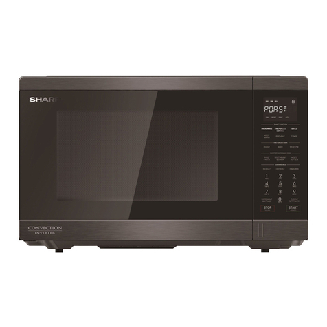
Sharp R-890SLM User manual

R-890SLM
CONTENTS
CHAPTER 1. BEFORE SERVICING
CHAPTER 2. WARNING TO SERVICE PERSONNEL
CHAPTER 3. PRODUCT SPECIFICATIONS
CHAPTER 4. APPEARANCE VIEW
CHAPTER 5. OPERATION SEQUENCE
CHAPTER 6. FUNCTION OF IMPORTANT
COMPONENTS
CHAPTER 7. TROUBLESHOOTING GUIDE
CHAPTER 8. TEST PROCEDURES
SERVICE MANUAL
S3905R890PKS
MICROWAVE OVEN WITH
GRILL AND CONVECTION
MODELS R-890SLM
This document has been published to be used for after sales service only.
The contents are subject to change without notice.
CHAPTER 9. CONTROL PANEL ASSEMBLY
CHAPTER 10. PRECAUTIONS FOR USING LEAD-FREE
SOLDER
CHAPTER 11. COMPONENT REPLACEMENT AND
ADJUSTMENT PROCEDURE
CHAPTER 12. MICROWAVE MEASUREMENT
CHAPTER 13. CIRCUIT DIAGRAMS
Parts List
In interests of user-safety the oven should be restored to its
original condition and only parts identical to those specified
should be used.
Service_R-890SLM.indd 1 4/25/09 10:54:28 AM

CHAPTER 1. BEFORE SERVICING
CHAPTER 2. WARNING TO SERVICE PERSONNEL
CHAPTER 3. PRODUCT SPECIFICATIONS
[1] SPECIFICATION .........................................3-1
CHAPTER 4. APPEARANCE VIEW
CHAPTER 5. OPERATION SEQUENCE
[1] OFF CONDITION ........................................5-1
[2] MICROWAVE COOKING CONDITION .......5-1
[3] GRILL COOKING CONDITION ...................5-2
[4] CONVECTION COOKING CONDITION .....5-2
[5] COMBI COOKING CONDITION ..................5-2
[6] ON/OFF TIME RATIO ..................................5-3
[7] AUTO POWER CONTROL OPERATION ....5-3
CHAPTER 6. FUNCTION OF IMPORTANT COM-
PONENTS
[1] DOOR OPEN MECHANISM ........................6-1
[2] SWITCH ......................................................6-1
[3] FUSE ...........................................................6-1
[4] TC TRANSFORMER ...................................6-1
[5] THERMAL CUT-OUT ...................................6-1
[6] ASYMMETRIC RECTIFIER .........................6-1
[7] NOISE FILTER ............................................6-2
[8] MOTOR .......................................................6-2
[9] HEATING ELEMENT ...................................6-2
[10] CONVECTION COOKING SYSTEM ...........6-2
[11] FIRE SENSING FEATURE ..........................6-2
[12] OPEN JUDGE BY THERMISTOR ...............6-2
CHAPTER 7. TROUBLESHOOTING GUIDE
CHAPTER 8. TEST PROCEDURES
[1] A: MAGNETRON TEST ...............................8-1
[2] B: HIGH VOLTAGE TRANSFORMER
TEST ...........................................................8-1
[3] C: HIGH VOLTAGE RECTIFIER TEST .......8-2
[4] D: HIGH VOLTAGE CAPACITOR TEST ......8-2
[5] E: SWITCH TEST ........................................8-2
[6] F: THERMISTOR TEST ...............................8-2
[7] G: THERMAL CUT-OUT TEST ....................8-3
[8] H: MOTOR WINDING TEST. .......................8-3
[9] I: NOISE FILTER TEST ...............................8-3
[10] J: BLOWN FUSE (F1) 20A ..........................8-3
[11] K: BLOWN FUSE F8A .................................8-3
[12] L: GRILL HEATING ELEMENTS (TOP)
AND BOTTOM HEATING ELEMENT
TEST ...........................................................8-4
[13] M: CONTROL PANEL ASSEMBLY TEST ....8-4
[14] N: JOG SWITCH UNIT TEST ......................8-4
CONTENTS
[15] O: RELAY TEST ..........................................8-5
[16] P: PROCEDURES TO BE TAKEN
WHEN THE FOIL PATTERN ON THE
PRINTED WIRING BOARD (PWB) IS
OPEN ..........................................................8-5
CHAPTER 9. CONTROL PANEL ASSEMBLY
[1] OUTLINE OF CONTROL PANEL ................9-1
[2] SERVICING FOR CONTROL PANEL .........9-2
CHAPTER 10. PRECAUTIONS FOR USING LEAD-
FREE SOLDER
CHAPTER 11. COMPONENT REPLACEMENT AND
ADJUSTMENT PROCEDURE
[1] BEFORE OPERATING ................................11-1
[2] OUTER CASE CABINET REMOVAL ..........11-1
[3] HIGH VOLTAGE COMPONENTS
REMOVAL ...................................................11-2
[4] HIGH VOLTAGE TRANSFORMER
REMOVAL ...................................................11-2
[5] MAGNETRON REMOVAL ...........................11-2
[6] FAN MOTOR REPLACEMENT ...................11-2
[7] TURNTABLE MOTOR REPLACEMENT .....11-3
[8] CONVECTION FAN MOTOR REMOVAL ....11-3
[9] POSITIVE LOCK CONNECTOR
REMOVAL ...................................................11-4
[10] OVEN LAMP REMOVAL .............................11-4
[11] POWER SUPPLY CORD REPLACE-
MENT ..........................................................11-4
[12] TOP HEATING ELEMENTS REMOVAL ......11-4
[13] BOTTOM HEATING ELEMENTS
REMOVAL ...................................................11-5
[14]
CONTROL PANEL ASSEMBLY REMOVAL
....11-5
[15]
MONITORED LATCH SWITCH, MONITOR
SWITCH AND STOP SWITCH REMOVA
L .....11-5
[16] MONITORED LATCH SWITCH, STOP SWITCH
AND MONITOR SWITCH ADJUSTMENT
......11-5
[17] DOOR REPLACEMENT ..............................11-6
CHAPTER 12. MICROWAVE MEASUREMENT
CHAPTER 13. CIRCUIT DIAGRAMS
[1] Oven Schematic ..........................................13-1
[2] Pictorial Diagram (Figure S-1) .....................13-6
[3] Control Unit Circuit ......................................13-7
[4] Printed Wiring Board of Control Unit ...........13-8
[5] Printed Wiring Board of Power Unit .............13-9
[6] Printed Wiring Board of Switch Unit ............13-10
Parts List
Service_R-890SLM.indd 2 4/25/09 10:54:33 AM

R-890SLM
CHAPTER 1. BEFORE SERVICING
[1] GENERAL IMPORTANT INFORMATION
This Manual has been prepared to provide Sharp Corp. Service engineers with Operation and Service Information.
It is recommended that service engineers carefully study the entire text of this manual, so they will be qualified to render satisfactory
customer service.
WARNING: THIS APPLIANCE MUST BE EARTHED
IMPORTANT
THE WIRES IN THIS MAINS LEAD ARE COLOURED IN ACCORDANCE WITH THE FOLLOWING CODE:
GREEN-AND-YELLOW ------------------------------- EARTH
BLUE -------------------------------------------------- NEUTRAL
BROWN -------------------------------------------------------LIVE
[2] WARNING MICROWAVE RADIATION
Personnel should not be exposed to the microwave energy which may radiate from the magnetron or other microwave
generating devices if it is improperly used or connected. All input and output microwave connections, waveguides, flanges
and gaskets must be secured. Never operate the device without a microwave energy absorbing load attached.
Never look into an open waveguide or antenna while the device is energized.
[3] WARNING
Never operate the oven until the following points are ensured.
(A) The door is tightly closed.
(B) The door brackets and hinges are not defective.
(C) The door packing is not damaged.
(D) The door is not deformed or warped.
(E) There is not any other visible damage with the oven.
Servicing and repair work must be carried out only by trained service engineers.
All the parts marked "S" on parts list are used at voltage more than 250V.
Removal of the outer wrap gives access to potential above 250V.
All the parts marked "*" on parts list may cause undue microwave exposure, by themselves, or when they are damaged,
loosened or removed.
Never operate the Grill and/ or Convection heater with the oven outer cabinet removed. (Because air flow is elimi-
nated, and the excess heat generated on adjacent components). It can cause permanent damage or a fire.
1 - 1
Service_R-890SLM.indd 3 4/25/09 10:54:34 AM

R-890SLM
CHAPTER 2. WARNING TO SERVICE PERSONNEL
Microwave ovens contain circuitry capable of producing very high voltage and current, contact with any part of the high voltage circuit
will result in electrocution. High voltage capacitor, Power transformer, Magnetron, High voltage rectifier assembly, High voltage fuse,
High voltage harness.
REMEMBER TO CHECK 4R
1)
Reconnect all leads removed from components during testing.
2) Replace the outer case (cabinet).
3) Reconnect the supply.
4) Run the oven. Check all functions.
Microwave ovens should not be run empty. To test for the
presence of microwave energy within a cavity, place a cup
of cold water on the oven turntable, close the door and set
the power level to HIGH (100%). And set the microwave
timer for two (2) minutes. When the two minutes has elapsed
(timer at zero) carefully check that the water is now hot. If the
water remains cold, carry out 3D checks and re-examine the
connections to the component being tested.
When all service work is completed and the oven is fully assembled, the microwave power output should be checked and microwave
leakage test should be carried out.
2 - 1
REMEMBER TO CHECK 3D
1) Disconnect the supply.
2) Door opened, and wedged open.
3) Discharge the high voltage capacitor.
WARNING: AGAINST THE CHARGE OF THE HIGH
VOLTAGE CAPACITOR
The high-voltage capacitor remains charged
about 60 seconds after the oven has been
switched off. Wait for 60 seconds and then
short-circuit the connection of the high voltag
capacitor (that is, of the connecting lead of
the high-voltage rectifier) against the chassis
with the use of an insulated screwdriver.
Sharp recommend that wherever possible fault-finding is
carried out with the supply disconnected. It may, in some
cases, be necessary to connect the supply after the outer
case has been removed, in this event carry out 3D checks
and then disconnect the leads to the primary of the power
transformer. Ensure that these leads remain isolated from
other components and the oven chassis. (Use insulation tape
if necessary.) When the testing is completed, carry out 3D
checks and reconnect the leads to the primary of the power
transformer.
Service_R-890SLM.indd 4 4/25/09 10:54:34 AM

R-890SLM
CHAPTER 3. PRODUCT SPECIFICATIONS
[1] SPECIFICATION
ITEM DESCRIPTION
Power Requirements 230 - 240 Volts / 50 Hertz / Single phase, 3 wire earthed
Power Consumption
Microwave cooking 1.50 kW Approx. 6.5A
Convection cooking 1.91 kW Approx. 8.0 A
Grill cooking
Top Grill mode ---------------------- 1.25kW Approx. 5.2A
Bottom Grill mode ----------------- 0.70kW Approx. 2.9A
Top and Bottom mode ------------ 1.90kW Approx. 7.9A
Combi cooking
Micro and Top Grill ---------------- 2.70kW Approx. 11.5A
Micro and Bottom Grill ------------2.15kW Approx. 9.2A
Micro and Convection ------------ 2.16kW Approx. 9.3A
Power Output 900 watts nominal of RF microwave energy (IEC60705 Test Procedure)
Operating frequency 2450 MHz
Top Grill heating element
Power Output 1200W
Bottom heating element
Power Output 650W
Outer Case Dimensions
Width 520 mm
Height 309 mm including foot
Depth 683.5 mm NOTE: The Depth does not include the door opening handle.
Cooking Cavity Dimensions
Width 353 mm
Height 207 mm
Depth 357 mm
NOTE: Internal capacity is calculated by measuring maximum width, depth
and height. Actual capacity for holding food is less.
Turntable diameter 325 mm
Control Complement
Jog Touch Control System
Clock (1:00 - 12:59) / Timer (0 - 99 minutes)
Microwave Power for Variable Cooking
Repetition Rate;
100P (HIGH) ......................................... Full power throughout the cooking time
70P (MEDIUM HIGH) ............................................ approx. 70% of FULL Power
50P (MEDIUM) ...................................................... approx. 50% of FULL Power
30P (MEDIUM LOW) ............................................. approx. 30% of FULL Power
10P (LOW) ............................................................ approx. 10% of FULL Power
Convection temperature control range:
250°C, 230°C, 220°C, 200°C, 180°C, 160°C, 130°C, 100°C, 70°C and 40°C
EXPRESS COOK button
EXPRESS DEFROST button
ENTER button
COMBI button
MICRO POWER button
GRILL button
CONV.(ºC) button
QUICK&EASY button
SHORT CUTS button
INFO button
AUTO COOK button
AUTO MINUTE button
STOP/CLEAR button
KITCHEN TIMER/CLOCK button
START button
ENCODER dial
ENTER button
Net Weight Approx. 19 kg
As part of our policy of continuous improvement, we reserve the right to alter design and specifications without notice.
3 - 1
Service_R-890SLM.indd 5 4/25/09 10:54:36 AM

R-890SLM
HELP 1
3245
1
16
4
6
17
2
6
7
3
5
7
8
9
10
12
11
13
15
14
CHAPTER 4. APPEARANCE VIEW
[1] OVEN
1. Control panel
2. Oven lamp
3. Waveguide cover
4. Bottom Grill heating element
5. Turntable motor shaft
6. Oven cavity
7. Door seals and sealing surfaces
8. Door latches
9. Door opening handle
10. Top Grill heating element
11. Convection fan
12. Ventilation openings
13. Outer case cabinet
14. Power cord
15. Turntable
16. High rack
17. Low rack
4 - 1
[2] TOUCH CONTROL PANEL
12
14
13
15
9
3
678 5 4
10 11
16
17
1
2
DIGITAL DISPLAY
INDICATORS:
1. LESS/MORE
2. INFO
3. COOK
4. MICROWAVE
5. CONVECTION
6. BOTTOM GRILL
7. TOP GRILL
1. DIGITAL DISPLAY
OPERATING BUTTONS:
2. EXPRESS COOK button
3. EXPRESS DEFROST buttons
4. MICRO POWER button
5. COMBI button
6. CONV.(ºC) button
7. GRILL button
8. SHORT CUTS button
9. QUICK & EASY button
10. AUTO MINUTE button
11. AUTO COOK button
12. INFO button
13. START button
14. KITCHEN TIMER button
15. STOP/CLEAR button
16. ENCODER dial
Rotate the dial so that light show on menu
17. ENTER button
Service_R-890SLM.indd 6 4/25/09 10:54:46 AM

R-890SLM
[1] OFF CONDITION
Closing the door activates the monitored latch switch and the
stop switch.
IMPORTANT
When the oven door is closed, the contacts COM-NC of the
monitor switch must be open. When the microwave oven is
plugged in a wall outlet (230 - 240V / 50Hz), the line voltage
is supplied to the noise filter.
Figure O-1 on page 13-1
1. The control unit is not energized. The display shows nothing
(Fig. O-1 (a)).
2. Open the door. The contacts (COM-NC) of the monitored
latch switch are closed and the control unit is energized.
Then contacts of relays RY1 and RY5 are closed, and the
oven lamp will light and the display will show “ENERGY
SAVE MODE TO CANCEL ENERGY SAVE MODE SET THE
CLOCK” (Fig. O-1(b)).
3. Close the door. The contacts (COM-NC) of the monitored
latch switch are opened and the contacts of relay RY1 are
opened and the oven lamp will be turned off. The display will
show “ . 0”. (Fig. O-1(c)).
NOTE: Energy save mode
1) If the oven has not been used for more than 3 min-
utes, the contacts of the relay RY5 will be opened
and the control unit will be not energized.
Open and close the door, the control unit will resume.
2)
If the clock is set, this energy save mode does not work.
[2] MICROWAVE COOKING CONDITION
1. HIGH COOKING
Press MICRO POWER button. And enter the cooking time by
rotate ENCODER dial. And start the oven by press START button.
Function sequence
Figure O-2 on page 13-2
CONNECTED COMPONENTS RELAY
Oven lamp, Turntable motor RY1
High voltage transformer RY2
Fan motor, RY6
1. The line voltage is supplied to the primary winding of the high
voltage transformer. The voltage is converted to about 3.3
volts A.C. output on the filament winding and high voltage of
approximately 2000 volts A.C. on the secondary winding.
2. The filament winding voltage (3.3 volts) heats the magnetron
filament and the high voltage (2000 volts) is sent to the
voltage doubling circuit, where it is doubled to negative
voltage of approximately 4000 volts D.C..
3. The 2450 MHz microwave energy produced in the magnetron
generates a wavelength of 12.24cm. This energy is
channelled through the waveguide (transport channel) into
the oven cavity, where the food is placed to be cooked.
4. When the cooking time is up, a signal tone is heard and the
relays RY1 + RY2 + RY6 go back to their home position. The
circuits to the oven lamp, high voltage transformer, fan motor
and turntable motor are cut off.
5. When the oven door is opened during a cooking cycle, the
switches come to the following condition.
CHAPTER 5. OPERATION SEQUENCE
SWITCH
CONTACT
CONDITION
DURING
COOKING
DOOR OPEN
(NO COOKING)
Monitored latch
switch
COM-NO
COM-NC
Closed
Opened
Opened
Closed
Stop switch COM-NO Closed Opened
Monitor switch COM-NO
COM-NC
Closed
Opened
Opened
Closed
The circuit to the high voltage transformer is cut off when the
contacts of relay RY2, and the contacts (COM-NO) of the moni-
tored latch switch and monitor switch are made open. The circuit
to the fan motor is cut off when the relay RY6 is made open.
The circuit to the turntable motor is cut off when the contacts
(COM-NO) of the monitored latch switch are made open. The
relay RY2 and RY6 are made open when the door is opened.
The oven lamp remains on even if the oven door is opened after
the cooking cycle has been interrupted, because the relay RY1
stays closed. Shown in the display is remaining time.
6. MONITOR SWITCH CIRCUIT
The monitor switch is mechanically controlled by the oven
door, and monitors the operation of the monitored latch switc
h.
1) When the oven door is opened during or after the cycle of
a cooking program, the monitored latch switch and stop
switch must open their contacts (COM-NO) first. After that
the contacts (COM-NC) of the monitor switch and monitored
latch can be closed.
2) When the oven door is closed, the contacts (COM-NC) of
the monitor switch SW3 must be opened and the contacts
(COM-NO) of monitor switch must be closed. After that the
contacts (COM-NO) of the monitored latch switch and the
stop switch are made closed, and the contacts (COM-NC)
of the monitored latch switch are made open.
3)
When the oven door is opened and the contacts (COM-NO)
of the monitored latch switch remain closed, the fuse F8A
will blow. Because the relay RY1 and monitor switch are
closed and a short circuit is caused.
2. MEDIUM HIGH, MEDIUM, MEDIUM LOW, LOW
COOKING
When the microwave oven is preset for variable cooking power,
the line voltage is supplied to the high voltage transformer
intermittently within a 32-second time base through the relay
contact which is coupled with the current-limiting relay RY2. The
following levels of microwave power are given.
SETTING;
100P (HIGH)
32 sec. ON
70P
(MEDIUM HIGH)
Approx. 70%
100%
24 sec. ON 8 sec. OFF
14 sec. OFF
20 sec. OFF
26 sec. OFF
18 sec. ON
30P
(MEDIUMLOW)
10P
(LOW)
50P
(MEDIUMLOW)
Approx. 30%
Approx. 50%
Approx. 10%
12 sec. ON
6 sec. ON
NOTE: The ON/OFF time ratio does not exactly correspond to
the percentage of microwave power, because approx.
3 seconds are needed for heating up the magnetron
filament.
5 - 1
Service_R-890SLM.indd 7 4/25/09 10:54:55 AM

R-890SLM
5 - 2
[3] GRILL COOKING CONDITION
1. TOP GRILL (Figure O-3)
In this condition the food is cooked by the top grill heating
element. Press GRILL button. And enter the cooking time by
rotate ENCODER dial. When the START button is pressed, the
following operation occur:
1.
The numbers on the digital readout start the count down to zero.
2. The oven lamp, cooling fan motor and turntable motor are
energized.
3. The relay RY3 is energized and the main supply voltage is
applied to the top grill heating element.
4. Now, the food is cooked by the top grill heating element.
2. BOTTOM GRILL (Figure O-3b)
In this condition the food is cooked by bottom grill heating
element energy. Press GRILL button 2 times. And enter the
cooking time by rotate ENCODER dial. When the START button
is pressed, the following operation occur:
1.
The numbers on the digital readout start the count down to zero.
2. The oven lamp, cooling fan motor and turntable motor are
energized.
3. The relay RY4 is energized and the main supply voltage is
applied to the bottom grill heating element.
4. Now, the food is cooked by the bottom grill heating element.
3. TOP AND BOTTOM GRILLS (Figure O-3c)
In this condition the food is cooked by top and bottom grill
heating elements energy. Press GRILL button 3 times. And
enter the cooking time by rotate ENCODER dial. When the
START button is pressed, the following operation occur:
1.
The numbers on the digital readout start the count down to zero.
2. The oven lamp, cooling fan motor and turntable motor are
energized.
3. The relay RY4 is energized and the main supply voltage is
applied to the bottom grill heating element.
4. The relay RY3 is energized and the main supply voltage is
applied to the top grill heating element.
5. Now, the food is cooked by the top and bottom grill heating
elements.
[4] CONVECTION COOKING CONDITION
1. PRE-HEATING (Figure O-4)
Press CONV. (ºC) button for programme the desired convection
temperature. When the INSTANT COOK/START button is
touched, the following operations occur:
1. The coil shut-off relays RY1 and RY6 are energized, the oven
lamp, cooling fan motor and turntable motor are turned on.
2. The coil shut-off relays RY3 and RY4 are energized by
control unit and the main supply voltage is added to the top
and bottom heating elements.
3. When the oven temperature reaches the selected pre-heat
temperature, the following operations occur:
1) The coil shut-off relays RY3 and RY4 are energized by
control unit temperature circuit and thermistor, opening the
circuit to the top and bottom grill heating elements.
2) The oven will continue to function for 30 minutes, turning
the top and bottom heating elements on and off, as needed
to maintain the selected pre-heat temperature. The oven
will shut-down completely after 30 minutes.
2. CONVECTION COOKING (Figure O-4)
When the pre-heat temperature is reached, a beep signal will
sound indicating that the holding the temperature has been
reached in the oven cavity. Open the door and place the food
to cooked in the oven. Press CONV.(ºC) button. And enter the
convection time by rotate ENCODER dial. When the START
button is pressed, the following operation occur:
1.
The numbers on the digital readout start the count down to zero.
2. The oven lamp, cooling fan motor, turntable motor and
convection motor are energized.
NOTE: When the convection temperature 40°C is selected, the
convection motor is not energized.
3. The relays RY3 and RY4 are energized (if the cavity
temperature is lower than selected temperature) and the
main supply voltage is applied to the top and bottom heating
elements to return to the selected cooking temperature.
4. Upon completion of the cooking time, the audible signal will
sound, and the oven lamp, turntable motor, cooling fan motor,
convection motor, top and bottom heating elements are de-
energized. At the end of convection cycle, if the cavity air
temperature rise above 120°C, the circuit to the relay RY6
will be maintained (by the thermistor circuit) to continue
operation of the cooling fan motor until temperature drops
below 105°C, at that time the relay RY6 will be de-energized,
turning off the fan motor.
[5] COMBI COOKING CONDITION
1. MICROWAVE AND CONVECTION (Figure O-5a)
Press MIX button 1 time. And enter the desired cooking time by
rotating the ENCODER dial. And press MICRO POWER button
to set the desired microwave power. And press the CONV. (ºC)
button to set the cooking temperature. When the INSTANT
COOK/START button is touched, the following operations occur:
1.
The numbers on the digital readout start the count down to zero.
2. The oven lamp, cooling fan motor, turntable motor and
convection motor are energized.
3. The relay RY3 will be energized and the main supply voltage
is applied to the top grill heating element.
4. The relay RY4 is energized (if the cavity temperature is lower
than selected temperature) and the main supply voltage is
applied to the bottom heating element.
5. The relay RY2 is energized and the microwave energy is
generated by magnetron.
6. Now, the food is cooked by microwave and convection
energy simultaneously
2. MICROWAVE AND TOP GRILL (Figure O-5b)
Press MIX button 2 times. And enter the desired cooking time
by rotating the ENCODER dial. And press MICRO POWER
button to set the desired microwave power. When the INSTANT
COOK/START button is touched, the following operations occur:
1.
The numbers on the digital readout start the count down to zero.
2. The oven lamp, cooling fan motor and turntable motor are
energized.
3. The relay RY3 is energized and the main supply voltage is
applied to the top grill heating element.
4. The relay RY2 is energized and the microwave energy is
generated by magnetron.
5. Now, the food is cooked by microwave and top grill
simultaneously.
Service_R-890SLM.indd 8 4/25/09 10:54:56 AM

R-890SLM
5 - 3
3. MICROWAVE AND BOTTOM GRILL (Figure O-5c)
Press MIX button 3 times. And enter the desired cooking time
by rotating the ENCODER dial. And press MICRO POWER
button to set the desired microwave power. When the INSTANT
COOK/START button is touched, the following operations occur:
1.
The numbers on the digital readout start the count down to zero.
2. The oven lamp, cooling fan motor and turntable motor are
energized.
3. The relay RY4 is energized and the main supply voltage is
applied to the bottom grill heating element.
4. The relay RY2 is energized and the microwave energy is
generated by magnetron.
5. Now, the food is cooked by microwave and bottom grill simul-
taneously.
POWER OUTPUT ON TIME OFF TIME
100% 54 sec. 0 sec.
90% 49 sec. 5 sec.
80% 45 sec. 9 sec.
70% 40 sec. 14 sec.
60% 36 sec. 18 sec.
50% 29 sec. 25 sec.
40% 24 sec. 30 sec.
30% 18 sec. 36 sec.
20% 13 sec. 41 sec.
10% 9 sec. 45 sec.
[6] ON/OFF TIME RATIO
In grill cooking, convection cooking or combi cooking, the top
heater, bottom heater or magnetron operate within a 54 second
time base. The following table is the ON / OFF time ratio at each
power output of the top heaters, bottom heater or magnetron.
[7] AUTO POWER CONTROL OPERATION
The magnetron, top or bottom heating elements, the fan motor or the convection motor will operate in accordance with following
specification.
1. OUTPUT POWER CONTROL (MANUAL COOK)
OPERATION MODE DEVICE POWER CONTROL
MICROWAVE (100%)
SINGLE OPERATION Microwave 100% 20min, then 70%
TOP GRILL (100%)
SINGLE OPERATION Top heater 100% 15min, then 50%
BOTTOM GRILL (100%)
SINGLE OPERATION Bottom heater 100% 15min, then 50%
TOP(100%)/BOTTOM(100%) Top heater 100% 6min then 70% and 70% 9min then 50%
COMBI OPERATION Bottom heater 100% 6min then 70% and 70% 9min then 50%
MICRO(100%)/TOP GRILL(100%) Microwave 100% 20min, then 70%
COMBI OPERATION Top heater 100% 15min, then 50%
MICRO(70 - 10%)/TOP GRILL(100%) Microwave -
COMBI OPERATION Top heater 100% 15min, then 50%
MICRO(100%)/BOTTOM GRILL(100%) Microwave 100% 20min, then 70%
COMBI OPERATION Bottom heater 100% 15min, then 50%
MICRO(70 - 10%)/BOTTOM GRILL(100%) Microwave -
COMBI OPERATION Bottom heater 100% 15min, then 50%
Repeat Cook
Microwave
Top heater
Bottom heater
In case same cooking mode is repeated within 1min 15sec
(including stop, end), oven calculates total cooking time and
reduce the power level.
2. OUTPUT POWER CONTROL (AUTO COOK)
OPERATION MODE DEVICE POWER CONTROL
Repeat Auto Cook Microwave
The power level is not reduced 1 time cooking. But only in
case same menu is repeated within 1min 15sec, the power
level of micro and grill is reduced from 100% to 70% in 20mins
after starting of last cooking. (Even if the time of the last cook-
ing is longer than 20mins, the power level isn’t reduced on the
last cooking, and it is reduced from the beginning of the next
cooking.) However, in time calculated from the start of the 1st
cooking, even if the Cook mode changed, when repetition
cooking of the menu with which 100% of top & bottom heaters
continues are performed, as shown in the following table, the
power down of the cooking of the 2nd henceforth is carried
out. (The 1st cooking is not applied)
Service_R-890SLM.indd 9 4/25/09 10:54:57 AM

R-890SLM
5 - 4
3. COOLING FAN OPERATION
OPERATION MODE DEVICE POWER CONTROL
PREHEAT Cooling 60%
CONV. (OVEN) Cooling fan 60% 60 min. then 100%
Others Cooling fan 100%
After cooking
Cooling fan A cooling fan continues the rotation when Oven temperature is more than 120°C.
Then, it stops when it is less than 105°C
Indication NOW COOLING is indicated during the cooling fan movement after operation is
finished. (It isn’t indicated during a fan movement to stop on the way.)
4. CONVECTION POWER SETTING
4.1. PREHEATING
TEMP 250°C, 230°C, 220°C, 200°C, 180°C, 160°C, 130°C, 100°C, 70°C, 40°C
HEATING ELEMENT TOP 100%
BOTTOM 100%
COOLING FAN 60%
CONV. FAN 0%
4.2. CONVECTION
TEMP
250°C 230°C 220°C 200°C 180°C 160°C 130°C 100°C 70°C 40°C
✩WITHOUT PREHEATING HEATING
ELEMENT
TOP 50% 40% 40% 30% 20% 10% 10% 10% 10% 10%
BOTTOM 100% 90% 80% 70% 70% 60% 50% 40% 30% 20%
✩WITH PREHEATING HEATING
ELEMENT
TOP 50% 40% 40% 30% 20% 10% 10% 10% 10% 10%
BOTTOM 90% 70% 60% 50% 50% 50% 50% 40% 30% 20%
COOLING FAN 60% 60min, then 100%
CONV. FAN 100% 0%
4.3. COMBI-1 (Micro + Conv)
TEMP
250°C 230°C 220°C 200°C 180°C 160°C 130°C 100°C 70°C 40°C
✩WITHOUT PREHEATING HEATING
ELEMENT
TOP 50% 40% 40% 30% 20% 10% 10% 10% 10% 10%
BOTTOM 100% 90% 80% 70% 70% 60% 50% 40% 30% 20%
✩WITH PREHEATING HEATING
ELEMENT
TOP 50% 40% 40% 30% 20% 10% 10% 10% 10% 10%
BOTTOM 90% 70% 60% 50% 50% 50% 50% 40% 30% 20%
MICRO 10%, 30%, 50%
COOLING FAN 100%
CONV. FAN 100% 0%
NOTE: ✩The oven temp was checked by the thermometer when each stage is started.
If the oven temp is same or higher than 105°C, the oven was judged as “with preheating”.
When the oven temp is lower than 105°C or the cooling fan stops, the oven was judged as “without preheating”.
Micro and Top heating element can’t be on at the same time.
Service_R-890SLM.indd 10 4/25/09 10:54:58 AM

R-890SLM
6 - 1
CHAPTER 6. FUNCTION OF IMPORTANT COMPONENTS
[1] DOOR OPEN MECHANISM
The door can be opened by pulling the door handle. When the
handle is pulled, the latch head is pulled, the latch head is moved
upward, and released from the latch hook now the door can be
opened.
Figure D-1. Door Open Mechanism
Latch hook
Door
Stop switch
Latch
Heads
Monitor switch
Monitored
latch switch
Tab
[2] SWITCH
1. MONITORED LATCH SWITCH
1. When the oven door is closed, the contacts (COM-NO) of the
switch must be closed. And the contacts (COM-NC) must be
opened.
2. When the oven door is opened, the contacts (COM-NO) of
the switch must be opened. And the contacts (COM-NC)
must be closed.
2. STOP SWITCH
1. When the oven door is closed, the contacts (COM-NO) of the
switch must be closed.
2. When the oven door is opened, the contacts (COM-NO) of
switch must be opened.
3. MONITOR SWITCH
The monitor switch is activated (the contacts opened) by the
upper latch head on the door while the door is closed. The switch
is intended to render the oven inoperative by means of blowing
the fuse F8A when the contacts of the monitored latch switch fail
to open when the door is opened.
Function
1. When the door is opened, the contacts (COM-NC) of monitor
switch close (to the ON condition) due to their being normally
closed and contacts (COM-NO) open. At this time the
contacts (COM-NO) of monitored latch switch is in the OFF
condition (contacts open) due to their being normally open
contact switches.
2. As the door goes to a closed position, the monitor switch
contacts (COM-NC) are opened and contacts (COM-NO)
closed and then contacts (COM-NO) of monitored latch
switch and stop switch are closed.(On opening the door,
each of these switches operate inversely.)
3. If the door is opened and the monitored latch switch contacts
(COM-NO) fail to open, the fuse F8A blows immediately after
closing of the monitor switch (COM-NC) contacts.
CAUTION: BEFORE REPLACING A BLOWN FUSE F8A,
TEST THE MONITORED LATCH SWITCH AND
MONITOR SWITCH FOR PROPER OPERATION.
(REFER TO CHAPTER “TEST PROCEDURE”).
[3] FUSE
1. FUSE 20A 250V
If the wire harness or electrical components are shortcircuited,
this fuse blows to prevent an electric shock or fire hazard.
2. FUSE F8A 250V
1.
If the wire harness or electrical components are shortcircuited,
this fuse blows to prevent an electric shock or fire hazard.
2. The fuse also blows when the monitored latch switch remains
closed with the oven door open and when the monitor switch
contact (COM-NC) closes.
3. The fuse also blows when the asymmetric rectifier, H.V.
rectifier, H.V. wire harness, H.V. capacitor, magnetron or
secondary winding of high voltage transformer is shorted.
[4] TC TRANSFORMER
T/C transformer converts A.C. line voltage into low voltage to
drive the control unit.
[5] THERMAL CUT-OUT
1. THERMAL CUT-OUT 125°C (MG)
This thermal cut-out protects the magnetron against overheat.
If the temperature goes up higher than 125°C because the fan
motor is interrupted or the ventilation openings are blocked, the
thermal cut-out will open and line voltage to the high voltage
transformer will cut off and operation of the magnetron will be
stopped. The defective thermal cut-out must be replaced with a
new one.
2. THERMAL CUT-OUT 145°C (OVEN)
This thermal cut-out protects against overheating /fire inside the
oven. The cut-out contacts will open when temperatures exceed
145°C. When the cut-out cools itself down to the operating
temperature of 115°C, the contacts of the thermal cut-out will
close again.
[6] ASYMMETRIC RECTIFIER
The asymmetric rectifier is solid state device that prevents current
flow is both directions. And it prevents the temperature rise of the
high voltage transformer by blowing the fuse F8A when the high
voltage rectifier is shorted.
The rated peak reverse voltage of D1 of the asymmetric rectifier
is 6 KV. The rated peak reverse voltage of D2 of the asymmetric
rectifier is 1.7 KV. D1 and D2 of the asymmetric rectifier or high
voltage rectifier are shorted when the each peak reverse voltage
goes beyond the each rated peak reverse voltage. (The process
of the blowing the fuse F8A.)
D2 D1
ASYMMETRIC
RECTIFIERHIGH VOLTAGE
RECTIFIER
1. The high voltage rectifier is shorted by some fault when
microwave cooking or combi cooking.
Service_R-890SLM.indd 11 4/25/09 10:55:02 AM

R-890SLM
6 - 2
2. The peak reverse voltage of D2 of the rectifier goes beyond
the rated peak reverse voltage 1.7 KV in the voltage doubler
circuit.
3. D2 of the rectifier is shorted.
4. The large electric currents flow through the high voltage
winding of the high voltage transformer.
5. The large electric currents beyond 8A flow through the
primary winding of the high voltage transformer.
6. The fuse F2 F8A blows by the large electric currents.
7.
The power supplying to the high voltage transformer is cut off.
[7] NOISE FILTER
The noise filter assembly prevents radio frequency interference
that might flow back in the power circuit.
[8] MOTOR
1. TURNTABLE MOTOR
The turntable motor rotates the turntable.
2. FAN MOTOR
The fan motor drives a blade which draws external cool air.
This cool air is directed through the air vanes surrounding the
magnetron and cools the magnetron. This air is channelled
through the oven cavity to remove steam and vapours given off
from heating food. It is then exhausted through the exhausting
air vents of the oven cavity.
3. CONVECTION MOTOR
The convection motor drives the convection fan and provide the
heated air.
[9] HEATING ELEMENT
1. TOP GRILL HEATING ELEMENT
The grill heating element is provided to brown the food and is
located on the top of the oven cavity.
2. BOTTOM GRILL HEATING ELEMENT
The grill heating element is provided to brown the food and is
located at the base of the oven cavity.
[10] CONVECTION COOKING SYSTEM
This oven is designed with a hot air heating system where food
is heated by forced circulation of the hot air produced by the grill
heating elements.
The air heated by the grill heating elements is circulated through
the convection passage provided on the outer casing of the oven
cavity by means of the convection fan which is driven by the
convection motor. It is then enters the inside of the oven through
the vent holes provided on the back side of the oven. Next, the
hot air heats the food on the turntable and leaves the oven cavity
through the vent in the oven cavity rear wall.
In this way, the hot air circulates inside the oven cavity to raise
its temperature and, at the same time, comes into contact with
the food being cooked. When the temperature inside the oven
cavity reaches the selected temperature, the heating elements
are de-energized. When the temperature inside the oven cavity
drops below the selected temperature, the heating elements
are energized again. In this way, the inside of the oven cavity is
maintained at approximately the selected temperature.
When the convection time reaches “0”, the heating elements
are de-energized and the convection fan stops operating and
the oven shuts off. At that time if the cavity air temperature has
rised above 120°C, the fan motor remains rotating. Automatically
the fan motor will be shut down at low temperature (less than
105°C).
Figure D-2. Convection Cooking System
Door Oven Cavity Grill Heating
Element
Bottom Grill
Heating Element
Convection
Passage
Cooling
Fan
Convection
Motor
Convection
Fan
Turntable
Insulation
Turntable
Motor
[11] FIRE SENSING FEATURE
The oven will stop its operation when there is a fire in the oven
cavity in microwave cooking condition.
LSI measures the voltage across the temperature measurement
circuit intermittently within 32-seconds time base since the oven
is started in microwave cooking condition. The oven will stop its
operation when the difference of the voltage is more than 0.781
volts in microwave cooking condition.
1.
Within a 32-seconds base, the thermistor is energized for 2
seconds. At that time, the voltage across the temperature
measurement circuit is measured.
2. The oven carries out the procedure above again. If the second
voltage is 0.781V higher than first voltage, LSI judges it as a
fire in the oven cavity and stop the oven.
3. When LSI judges it as a fire in the oven cavity, LSI will switch
off the relays to high voltage transformer and fan motor and
LSI stops countering down.
THERMISTOR
SENSING
VOLTAGE
ON
OFF
ON
OFF
30 32 (sec.)
Sensing the voltage across temperature measurement circuit.
[12] OPEN JUDGE BY THERMISTOR
1. If the temperature of the thermistor does not rise to more than
40°C after 4 minutes and 15 seconds from when the oven
is started in convection, grill (top and bottom grills) or combi
cooking mode, the oven is turned off.
2. When the thermistor or the wire harness to the thermistor is
opened, the oven is turned off after 4 minutes and 15 seconds
because this condition is same as above.
Service_R-890SLM.indd 12 4/25/09 10:55:06 AM

R-890SLM
7 - 1
CHAPTER 7. TROUBLESHOOTING GUIDE
When troubleshooting the microwave oven, it is helpful to follow the Sequence of Operation in performing the checks. Many of the
possible causes of trouble will require that a specific test be performed. These tests are given a procedure letter which will be found in
the “Test Procedure” section.
IMPORTANT:
If the oven becomes inoperative because of a blown fuse F8A in the monitored latch switch - monitor switch circuit, check the monitored
latch switch and monitor switch before replacing the noise filter (fuse F8A).
Service_R-890SLM.indd 13 4/25/09 10:55:06 AM

R-890SLM
7 - 2
.
d
e
n
e
p
osirood
e
htnehwswol
b
A8F
e
suF
.
te
l
tuol
law
o
tni
de
ggulpsi
d
ro
c
r
ew
o
p
nehwsw
ol
besu
f
emoH
.tel
tuo
ll
aw
o
tni
de
gg
ul
p
sidrocrewop
n
ehwswolbA02
e
suF
tel
tuo
l
law
o
tn
ideggulp
sid
ro
c
rewo
p
nehwy
al
psi
dn
isra
eppagn
ih
toN
.d
es
olcdna
d
e
n
e
p
os
i
roodeh
t
dna
.des
s
erpsino
t
tubPOTSne
h
wylrepor
p
e
t
arepoton
seod
yalpsiD
)
.se
tar
epoy
alpsiD(.d
enepo
sirood
nehw
t
h
gilton
s
e
o
dpma
l
nevO
)
.
seta
re
poyalps
i
D
(.
de
s
se
r
psino
t
tu
b
T
R
AT
S
e
h
tn
e
h
w
t
r
a
tst
ons
e
o
dne
vO
.e
ta
repoton
seodro
tom
e
lba
tnrut
dna
thg
il
t
o
nseod
p
m
a
lnev
O
).sth
g
il
pma
lnevO(.e
ta
repot
o
n
s
e
o
d
r
otomn
aF
).sthgilpmalnevO(.etarepotonseod
ro
tomna
f
noitc
ev
n
oC
)
.
s
th
gilpmal
nevO
(.e
ta
repoton
seodro
t
o
m
el
ba
tnruT
nehwpot
s
ton
seod
)r
o
tomnaf
tpe
cxe
(
strap
l
a
c
ir
t
ce
leynar
o
ne
v
O
.des
se
rps
i
not
tub
P
O
T
S
ro0s
i
emi
t
gn
ik
oo
c
n
o
ttubTRA
TS
ecniss
dn
oces
51d
nasetunim4
re
tfaspot
s
n
e
vO
.desser
p
s
i)
s
edomkooCibmoCdnaevaworciMtpecxE(
.etarep
o
tonodstrapla
c
irtcelellatubylreporpsetare
p
oyalp
s
iD
.
el
c
y
cg
ni
ko
ocf
od
nee
rof
ebnwod
s
tuhs
tu
bel
c
y
c
koo
c
otniseog
ne
v
O
tubC
º
501nahtr
eh
gihsiytivacnevofoeru
ta
repme
t
eh
t
,
gn
ik
oo
cre
t
fA
.etarepotonseod
r
otomnaf
nevonidecudo
rps
i
taeh
on
roel
t
ti
l
tubgni
ta
repoeb
o
t
smee
snevO
)
H
GIHtatessilortnocrewop
e
vaworciM(.daol
gn
i
koocelbai
ra
vgni
rud
ylre
po
rp
gn
ita
re
poebo
t
meestonse
od
nevO
.noi
t
idno
c
gn
i
kooc
H
G
I
H
tpe
cxe
no
it
idnoc
.
el
c
yc
g
nik
o
ocfo
d
neer
of
ebnwod
s
tuhst
u
bel
c
yckoo
c
otniseogn
e
vO
.taehtonseodedomgnikoocnoitcevnoC
s
i
y
t
i
vac
ne
v
o
eh
t
n
i
eru
ta
repme
teh
ttub
gn
i
tar
epo
eb
o
t
smees
nevO
.e
note
se
rp
nah
trehgihrorewol
.etarepo
se
odtnemelegni
tae
hl
l
irG
.
e
lcycg
n
iko
o
cfod
ne
erof
e
bn
w
ods
tu
hstu
b
elcyckooc
ot
ni
s
eognevO
nevonidecudorpsitaehonroelttiltubgnitarepoebotsmeesnevO
)ylrep
o
rpdetarenegeb
o
tmeestonseodrewop
e
v
a
w
o
r
c
iM(.daol
s
i
y
t
i
vac
ne
v
o
eh
t
n
i
eru
ta
repme
teh
ttub
gn
i
tar
epo
eb
o
t
smees
nevO
.enoteserpnahtrehgihrorewol
.taeht
on
odstnemele
g
nita
eh
l
l
irGmottoBdnapoT
.taehton
seod
tnemele
gn
it
aeh
l
l
irGmottoBro
po
T
F
FO
NOITIDNOC
G
NI
KO
O
C
NOITIDN
O
C
)E
DO
MNOMMOC(
EVAW
O
RCIM
GNI
K
O
OC
N
O
IT
I
DNO
C
GNIKOOCLLIRG
N
O
I
TI
DNO
C
N
O
I
TCEV
N
OC
GN
I
K
O
OC
N
OITID
N
OC
G
NI
K
O
O
CI
B
M
OC
N
OITID
N
OC
)
E
D
O
M
NO
MMOC(
IBMOC
GNI
K
O
OC
N
O
I
TID
NO
C
).
V
N
O
C/.
O
RCIM(
IBMOC
GNIKO
O
C
N
O
IT
I
DNOC
)LLIRG/.
O
RCIM(
NOITI
D
N
O
C
M
EL
B
O
RP
BLOCKED
COOLING FAN
BLOCKED
CONVECTION FAN
NO POWER AT WALL OUTLET
HOME FUSE OR BREAKER
MIS-ADJUSTMENT OF SWITCHES
BLOCKED VENTILATION OPENINGS
OPENED WIRE HARNESS
SHORTED WIRE HARNESS
POWER SUPPLY CORD
FOIL PATTERN ON P.W.B.
RELAY RY7
RELAY RY6
RELAY RY5
RELAY RY4
RELAY RY3
RELAY RY2
RELAY RY1
JOG SWITCH UNIT
CONTROL PANEL ASSEMBLY
TC TRANSFORMER
BOTTOM GRILL HEATING ELEMENT
TOP GRILL HEATING ELEMENT
NOISE FILTER (FUSE F8A)
FUSE 20A
NOISE FILTER
CONVECTION FAN MOTOR
FAN MOTOR
TURNTABLE MOTOR
THERMAL CUT-OUT 145ºC (OVEN)
THERMAL CUT-OUT 125ºC (MG)
THERMISTOR
MONITOR SWITCH
STOP SWITCH
MONITORED LATCH SWITCH
HIGH VOLTAGE CAPACITOR
H.V. HARNESS
H.V. RECTIFIER ASSEMBLY
HIGH VOLTAGE TRANSFORMER
MAGNETRON
HH
H
G
G
F
E
EE
D
CBA
ERUDECORPTSET
ESUA
C
EL
B
IS
S
OP
DNA
S
TR
AP
E
VITCEFED
Q
P
OO
OOOO
ONMLLKJI
OVEN LAMP
Service_R-890SLM.indd 14 4/25/09 10:55:10 AM

R-890SLM
8 - 1
CHAPTER 8. TEST PROCEDURES
[1] A: MAGNETRON TEST
NEVER TOUCH ANY PART IN THE CIRCUIT WITH YOUR HAND OR AN INSULATED TOOL WHILE THE OVEN IS IN OPERATION.
CARRY OUT 3D CHECKS.
Isolate the magnetron from high voltage circuit by removing all leads connected to filament terminal.
To test for an open circuit filament use an ohmmeter to make a continuity test between the magnetron filament terminals, the meter
should show a reading of less than 1 ohm.
To test for short filament to anode condition, connect ohmmeter between one of the filament terminals and the case of the magnetron
(ground). This test should be indicated an infinite resistance. If a low or zero resistance reading is obtained then the magnetron should
be replaced.
1. MICROWAVE OUTPUT POWER
The power output of this oven is rated using the method specified by IEC 60705. Full details of how to curry out this procedure can be
found in the Sharp Technical Training notes which is available from Sharp Parts Centre (part number SERV-LITMW01).
The IEC60705 procedure must be carried out using laboratory-type procedures and equipment.
These requirements make the procedure unsuitable for routine performance checks.
NOTE: The following test method gives an indication of the output power only, it cannot be used to establish the actual/rated
output power. If the true output power is required, then the IEC60705 test method must be used.
Alternative simplified method:
1. Place 2 litres of cold water (between 12°C and 20°C) in a suitable container.
2. Stir the water and measure the temperature in °C. Note temperature as T1.
3. Place the container in the microwave and heat the water for 1 minute and 36 seconds on full power.
NOTE: The operation time of the microwave oven includes “3” sec. (3 sec. is magnetron filament heat-up time.)
4. When the 1 minute and 36 seconds is completed, remove the container and stir the water. Note the water temperature as T2.
5. Calculate the output power using the following formula:
R.F. Power Output = (T2 - T1) x 90.
NOTE: The result from this test should be within the allowance of 2000cc alternative method. (±10%).
2. MICROWAVE LEAKAGE TEST
This oven should be tested for microwave leakage on completion of any repair or adjustment, following the procedure described in
the Sharp Technical Training notes (part number SERV-LITMW01). The maximum leakage permitted in BS EN 60335-2-25 is 50W/m2
(equivalent to 5W/m2), however it is not normal to detect any significant leakage, therefore, any leakage which is detected should be
investigated.
It is essential that only leakage detectors with current calibration traceable to National Physical Laboratories are used.
Suitable leakage detectors: CELTEC A100
APOLLO X1
[2] B: HIGH VOLTAGE TRANSFORMER TEST
WARNING: High voltages and large currents are present at the secondary winding and filament winding of the power
transformer. It is very dangerous to work near this part when the oven is on. NEVER make any voltage
measurements of the high-voltage circuits, including the magnetron filament.
1. CARRY OUT 3D CHECKS.
2. Disconnect the leads to the primary winding of the high voltage transformer. Disconnect the filament and secondary winding
connections from the rest of the HV circuitry. Using an ohmmeter, set on a low range, it is possible to check the continuity of all
three winding. The following readings should be obtained:
a.Primary winding -------------------- approximately 2.1 Ω
b.Secondary winding --------------- approximately 133 Ω
c.Filament winding --------------------------- less than 1 Ω
If the readings obtained are not stated as above, then the high voltage transformer is probably faulty and should be replaced.
3. Also, the high voltage transformer has the thermal cut-out in the primary coil. The thermal cut-out will open when the temperature
of the thermal cut-out in the primary coil reaches approximately 150°C. The thermal cut-out resets automatically at 130°C. If an
ohmmeter indicates an open circuit under normal condition, replace the high voltage transformer because the primary coil (thermal
cut-out) has opened. An open primary coil (thermal cut-out) indicates overheating of the high voltage transformer. Check for
restricted air flow to the high voltage transformer, especially the ventilation opening.
4. CARRY OUT 4R CHECKS.
Service_R-890SLM.indd 15 4/25/09 10:55:13 AM

R-890SLM
D2 D1
ASYMMETRIC
RECTIFIERHIGH VOLTAGE
RECTIFIER
A B
C
[3] C: HIGH VOLTAGE RECTIFIER TEST
CARRY OUT 3D CHECKS.
Isolate the high voltage rectifier assembly from the HV circuit. The high voltage rectifier can be tested using an ohmmeter set to its
highest range.
Connect the ohmmeter across the terminal B+C of the high voltage rectifier and note the reading obtained. Reverse the meter leads
and note this second reading. The normal resistance is infinite in one direction and more than 100 kΩ in the other direction.
CARRY OUT 4R CHECKS.
ASYMMETRIC RECTIFIER TEST
CARRY OUT 3D CHECKS.
Isolate the high voltage rectifier assembly from the HV circuit. The asymmetric rectifier can be
tested using an ohmmeter set to its highest range across the terminals A+B of the asymmetric
rectifier and note the reading obtained. Reverse the meter leads and note this second reading.
If an open circuit is indicated in both directions then the asymmetric rectifier is good. If the
asymmetric rectifier is shorted in either direction, then the asymmetric rectifier is faulty and must be replaced with high voltage recti-
fier. When the asymmetric rectifier is defective, check whether magnetron, high voltage rectifier, high voltage wire or filament winding
of the high voltage transformer is shorted.
CARRY OUT 4R CHECKS.
NOTE: FOR MEASUREMENT OF THE RESISTANCE OF THE RECTIFIER, THE BATTERIES OF THE MEASURING INSTRUMENT
MUST HAVE A VOLTAGE AT LEAST 6 VOLTS, BECAUSE OTHERWISE AN INFINITE RESISTANCE MIGHT BE SHOWN IN
BOTH DIRECTIONS.
[4] D: HIGH VOLTAGE CAPACITOR TEST
CARRY OUT 3D CHECKS.
1. Isolate the high voltage capacitor from the circuit.
2. Continuity check must be carried out with measuring instrument which is set to the highest resistance range.
3. A normal capacitor shows continuity for a short time (kick) and then a resistance of about 10MΩ after it has been charged.
4. A short-circuited capacitor shows continuity all the time.
5. An open capacitor constantly shows a resistance about 10 MΩ because of its internal 10MΩ resistance.
6. When the internal wire is opened in the high voltage capacitor shows an infinite resistance.
7. The resistance across all the terminals and the chassis must be infinite when the capacitor is normal.
If incorrect reading are obtained, the high voltage capacitor must be replaced.
CARRY OUT 4R CHECKS.
[5] E: SWITCH TEST
CARRY OUT 3D CHECKS.
Isolate the switch to be tested and using an ohmmeter check between the terminals as described in the following table.
Table: Terminal Connection of Switch
Plunger Operation Common terminal to Normally open terminal Common terminal to Normally close terminal
Released Open circuit Short circuit
Depressed Short circuit Open circuit
If incorrect readings are obtained, make the necessary switch adjustment or replace the switch.
CARRY OUT 4R CHECKS.
[6] F: THERMISTOR TEST
CARRY OUT 3D CHECKS.
Disconnect the connector B from CPU unit. Measure the resistance of the thermistor with an ohmmeter. Connect the ohmmeter leads
to Pin No’s C1 and C3 of the thermistor harness.
Room Temperature Resistance
20°C - 30°C Approximately 359.9 kΩ - 152 kΩ
If the meter does not indicate above resistance, replace the thermistor.
CARRY OUT 4R CHECKS.
8 - 2
Service_R-890SLM.indd 16 4/25/09 10:55:15 AM

R-890SLM
8 - 3
[7] G: THERMAL CUT-OUT TEST
CARRY OUT 3D CHECKS.
Disconnect the leads from the terminals of the thermal cut-out. Then using an ohmmeter, make a continuity test across the two
terminals as described in the below.
Table: Thermal Cut-out Test
Parts Name Temperature of “ON” condition
(closed circuit).
Temperature of “OFF” condition
(open circuit).
Indication of ohmmeter (When
room temperature is approx. 20°C.)
Thermal cut-out 125°C This is not resetable type. Above 125°C Closed circuit
Thermal cut-out 145°C Below 115°C. Above 145°C Closed circuit
If incorrect readings are obtained, replace the thermal cut-out.
An open circuit thermal cut-out (MG) indicates that the magnetron has overheated, this may be due to resistricted ventilation, cooling
fan failure.
An open circuit thermal cut-out (OVEN) indicates that the oven cavity has overheated, this may be due to no load operation, or exces-
sive heat / fire inside the oven.
CARRY OUT 4R CHECKS.
[8] H: MOTOR WINDING TEST
CARRY OUT 3D CHECKS.
Disconnect the leads from the motor. Using an ohmmeter, check the resistance between the two terminals as described in the table
below.
Table: Resistance of Motor
Motors Resistance
Fan motor Approximately 399Ω
Turntable motor Approximately 14.7kΩ
Convection fan motor Approximately 288kΩ
If incorrect readings are obtained, replace the motor.
CARRY OUT 4R CHECKS.
[9] I: NOISE FILTER TEST
CARRY OUT 3D CHECKS.
Disconnect the leads from the terminals of the noise filter.
Using an ohmmeter, check between the terminals as described in the following table.
MEASURING POINT INDICATION OF OHMMETER
Between N and L Approximately 680kΩ
Between terminal N and WHITE Short circuit
Between terminal L and RED Short circuit
If incorrect readings are obtained, replace the noise filter unit.
CARRY OUT 4R CHECKS.
[10] J: BLOWN FUSE 20A
CARRY OUT 3D CHECKS.
If the fuse 20A is blown, there is a shorts or grounds in electrical parts or wire harness. Check them and replace the defective parts or
repair the wire harness.
CARRY OUT 4R CHECKS.
CAUTION: Only replace fuse with the correct value replacement.
[11] K: BLOWN FUSE F8A
CARRY OUT 3D CHECKS.
1. If the fuse F8A is blown when the door is opened, check the monitored latch switch and monitor switch.
2. If the fuse F8A is blown by incorrect door switching replace the defective switch(es) and the noise filter (fuse F8A).
3. If the fuse F8A is blown, there could be shorts in the asymmetric rectifier or there is a ground in wire harness. A short in the
asymmetric rectifier may be occurred due to short or ground in H.V. rectifier, magnetron, high voltage transformer or H.V. wire.
Check them and replace the defective parts or repair the wire harness.
CARRY OUT 4R CHECKS.
F8A
20A
WHT
RED
R1
R2
N
Cx
Cy
L
L
L
L (min) Cx ± 20% Cy ± 20% R1 R2
1.0mH 0.22 uF 4700pF 10 M 680k
Service_R-890SLM.indd 17 4/25/09 10:55:18 AM

R-890SLM
[12] L: GRILL HEATING ELEMENTS (TOP) AND BOTTOM HEATING ELEMENT TEST
CARRY OUT 3D CHECKS.
Before carrying out the following tests make sure the heating element is cool completely.
1. Resistance of heater.
Disconnect the wire leads to the heating element to be tested. Using ohmmeter with low resistance range. Check the resistance
across the terminals of the heating element as described in the following table.
Table: Resistance of heater
Parts name Resistance
Grill heating element (Top) Approximately 48
Bottom heating element Approximately 92Ω
2. Insulation resistance.
Disconnect the wire leads to the heating element to be tested. Check the insulation resistance between the element terminal and
cavity using a 500V - 100MΩ insulation tester. The insulation resistance should be more than 10MΩ in the cold start.
If the results of above test 1 and/or 2 are out of above specifications, the heating element is probably faulty and should be replaced.
CARRY OUT 4R CHECKS.
[13] M: CONTROL PANEL ASSEMBLY TEST
The control panel consists of circuits including semiconductors such as LSI, ICs, etc. Therefore, unlike conventional microwave ovens,
proper maintenance can not be performed with only a voltmeter and ohmmeter.
In this service manual, the control panel assembly is divided into two units, Control Unit and Jog switch Unit, and troubleshooting by
replacement is described according to the symptoms indicated.
1. Jog switch Unit Note: Check Jog switch unit wire harness connection before replacement.
The following symptoms indicate a defective Jog switch unit. Replace the Jog switch unit.
1.1. Tact switch
1) When touching the buttons, a certain button produces no signal at all.
2) When touching the buttons, sometimes a button produces no signal.
1.2. Potentiometer
1) When rotating the potentiometer, the cooking mode can not be selected.
1.3. Encoder
1) When rotating the encoder, the cooking time or the weight of food can not be entered.
2. Control Panel
The following symptoms indicate a defective control unit. Before replacing the control unit, perform the Jog switch unit test (Procedure N)
to determine if control unit is faulty.
2.1. In connection with buttons
1) When touching the buttons, a certain group of buttons do not produce a signal.
2) When touching the buttons, no buttons produce a signal.
2.2. In connection with indicators
1) At a certain digit, all or some segments do not light up.
2) At a certain digit, brightness is low.
3) Only one indicator does not light up.
4) The corresponding segments of all digits do not light up; or they continue to light up.
5) Wrong figure appears.
6) A certain group of indicators do not light up.
7) The figure of all digits flicker.
2.3. Other possible troubles caused by defective control unit.
1) Buzzer does not sound or continues to sound.
2) Clock does not operate properly.
3) Cooking is not possible.
4) Proper temperature measurement is not obtained.
[14] N: JOG SWITCH UNIT TEST
If the display fails to clear when the STOP button is depressed, first verify the cable is making good contact, verify that the stop switch
operates properly; that is the contacts are closed when the door is closed and open when the door is open. If the stop switch is good,
disconnect the cable that connects the Jog switch unit to the control unit and make sure the stop switch is closed (either close the
door or short the stop switch connector). Use the Jog switch unit matrix indicated on the control panel schematic and place a jumper
wire between the pins that correspond to the STOP button making momentary contact. If the control unit responds by clearing with a
beep the Jog switch unit is faulty and must be replaced. If the control unit does not respond, it is a faulty and must be replaced. If a
specific button does not respond, the above method may be used (after clearing the control unit) to determine if the control unit or Jog
switch unit is at fault.
8 - 4
Service_R-890SLM.indd 18 4/25/09 10:55:19 AM

R-890SLM
a
7
0
P
J
1
S
A-NC
[15] O: RELAY TEST
CARRY OUT 3D CHECKS.
Remove the outer case and check voltage between Pin Nos. 5 and 7 of the 4 pin connector (E) on the control unit with an A.C.
voltmeter. The meter should indicate 230-240 volts, if not check oven circuit.
Relay Test
Check voltage at the relay coil with a D.C. voltmeter during the microwave cooking operation, grill operation, convection operation or
combi operation.
DC. voltage indicated ............................Defective relay.
DC. voltage not indicated ......................Check diode which is connected to the relay coil. If diode is good, control unit is defective.
RELAY SYMBOL OPERATIONAL VOLTAGE CONNECTED COMPONENTS
RY1 APPROX. 18.0V D.C. Oven lamp / Turntable motor
RY2 APPROX. 18.0V D.C. High voltage transformer
RY3 APPROX. 24.0V D.C. Grill (Top) heating element
RY4 APPROX. 24.0V D.C. Bottom heating element
RY5 APPROX. 24.0V D.C. Touch control transformer
RY6 APPROX. 24.0V D.C. Fan motor
RY7 APPROX. 24.0V D.C. Convection motor
CARRY OUT 4R CHECKS.
[16] P: PROCEDURES TO BE TAKEN WHEN THE FOIL PATTERN ON THE PRINTED WIRING BOARD
(PWB) IS OPEN
To protect the electronic circuits, this model is provided with a fine foil pattern added to the input circuit on the PWB, this foil pattern
acts as a fuse. If the foil pattern is open, follow the troubleshooting guide given below for repair.
Problem: POWER ON, indicator does not light up.
CARRY OUT 3D CHECKS.
STEPS OCCURRENCE CAUSE OR CORRECTION
1The rated AC voltage is not present between Pin Nos.
5 and 7 of the 4-pin connector (E). Check supply voltage and oven power cord.
2The rated AC voltage is present at primary side of low
voltage transformer.
Low voltage transformer or secondary circuit defective.
Check and replace the touch control transformer or the
control unit.
3 Pattern at “a” is broken. Replace the control unit.
(CARRY OUT 3D CHECKS BEFORE REPAIR)
NOTE: *At the time of these repairs, make a visual inspection of the varistor for burning
damage and examine the transformer with tester for the presence of layer short
circuit (check primary coil resistance).
If any abnormal condition is detected, replace the control unit.
CARRY OUT 4R CHECKS.
8 - 5
WH3-7
WH3-8
WH3-10 WH3-9
4-
3H
W
3
-
3
HW
2-
3
H
W
1
-
3HW
S
SE
RPXE
K
O
O
C
SW1
/
P
OT
S
RAEL
C
SW13
KITCHEN TIMER
/ CLOCK SET
SW14
L
L
IR
G
SW6
IB
N
O
C
SW4
T
RATS
SW15
OFN
I
SW10
ETUNIM OTUA
SW12
KOOC OTUA
SW11
SHORT CUTS
SW9
SY
A
E&
K
C
I
U
Q
SW8
)
(
.V ?NOC
SW7
RETNE
SW3
REWO
P
O
R
C
IM
SW5
SS
E
RPXE
TSOR
F
ED
SW2
CARRY OUT 4R CHECKS.
Service_R-890SLM.indd 19 4/25/09 10:55:24 AM

R-890SLM
9 - 1
CHAPTER 9. CONTROL PANEL ASSEMBLY
[1] OUTLINE OF CONTROL PANEL
The control section consists of the following units as shown in
the control panel circuit.
(1) Jog Switch Unit
(2) Control Unit
The principal functions of these units and signals communicated
among them are explained below.
1. Jog Switch Unit
The jog switch unit is composed of a matrix, signals generated
in the LSI are sent to the jog switch unit from P42 – P45.
When a button is touched, a signal is completed through the jog
switch unit and passed back to the LSI through P00, P20, P21
and P22 to perform the function that was requested.
2. Control Unit
Control unit consists of LSI, power source circuit, synchronizing
signal circuit, reset circuit, buzzer circuit, indicator circuit,
encoder circuit, potentiometer circuit, temperature measurement
circuit and back light circuit.
1) LSI
This LSI controls the temperature measurement signal, tact
switch strobe signal, relay driving signal for oven function
and indicator signal.
2) Power Source Circuit
This circuit generates voltage necessary in the control unit.
Symbol Voltage Application
VC -5.2V LSI(IC1)
3) Synchronizing Signal Circuit
The power source synchronizing signal is available in
order to compose a basic standard time in the clock circuit.
It accompanies a very small error because it works on
commercial frequency.
4) Reset Circuit
A circuit to generate a signal which resets the LSI to the
initial state when power is supplied.
5) Buzzer Circuit
The buzzer is responsive to signals from the LSI to emit
audible sounds (tact switch touch sound and completion
sound).
6) Stop Switch
A switch to “tell” the LSI if the door is open or closed.
7) Relay Circuit
To drive the magnetron, top and bottom heating element,
convection motor, fan motor, turntable motor, touch control
transformer and light the oven lamp.
8) Encoder
The encoder converts the signal generated by LSI into the
pulse signal, and the pulse signal is returned to the LSI.
9) Potentiometer Circuit
The circuit makes setting of the cooking mode by variable
resistance.
10) Back Light Circuit
A circuit to drive the back light (Light emitting diodes LD1 -
LD10).
11) Indicator Circuit
This circuit consists 7-digits, 27-segments and 4-common
electrodes using a Liquid Crystal Display.
12) Temperature Measurement Circuit: (OVEN THERMISTOR)
The temperature in the oven cavity is sensed by the
thermistor. The variation of resistance according to sensed
temperature is detected by the temperature measurement
circuit and the result applied to LSI. The LSI uses this
information to control the relay and display units.
Service_R-890SLM.indd 20 4/25/09 10:55:25 AM
Other manuals for R-890SLM
1
Table of contents
Other Sharp Microwave Oven manuals

Sharp
Sharp R652BK User manual

Sharp
Sharp R-42B User manual

Sharp
Sharp Carousel R-1514 User manual

Sharp
Sharp R-292 User manual

Sharp
Sharp R-880D Use and care manual

Sharp
Sharp Carousel R-395N User manual

Sharp
Sharp Carousel R-1501 Use and care manual

Sharp
Sharp R-898M User manual

Sharp
Sharp KB-6021MK Assembly instructions

Sharp
Sharp R-209FK User manual

Sharp
Sharp R-25JTF User manual

Sharp
Sharp R-330Y Use and care manual

Sharp
Sharp R-1520LK User manual

Sharp
Sharp R-23AT User manual

Sharp
Sharp R-600 User manual

Sharp
Sharp YB-S4202AE User manual

Sharp
Sharp R-297F User manual

Sharp
Sharp R-1880LST User manual

Sharp
Sharp R-20ST User manual

Sharp
Sharp R-342E Use and care manual