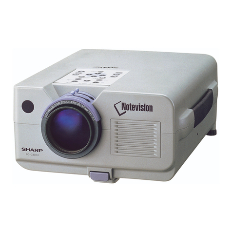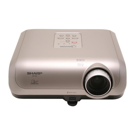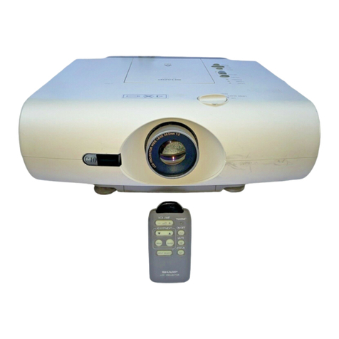
XG-V10WU
XG-V10WE
1
TECHNICAL MANUAL
TX0L1XG-V10WU
MODELS XG-V10WU
XG-V10WE
This Technical Manual is now prepared to help servicing the
LCD Projector equipped models,and its descriptions are lim-
ited only to“Description of New Circuit”etc.
For more understanding of each model,refer to its respective
Service Manual already issued.
(This Technical Manual is based on Models XG-V10WU and
XG-V10WE.)
LCD PROJECTOR
CONTENTS
Page
1.CVIC INTERNAL BLOCK DIAGRAM ........................... 2
2.CONNECTION BETWEEN CVIC AND SDRAM........... 4
2-1.SDRAM (HY57V653220B-TC7)............................. 6
2-1-1. Description ...................................................... 6
2-1-2. Features .......................................................... 6
2-1-3. Pin layout ........................................................ 7
2-1-4. Pin description ................................................ 7
3.INPUT WIRING DIAGRAM AND ROUTE DIAGRAM ... 8
3-1.IX3434CE (Input section)..................................... 13
3-1-1. Outline........................................................... 13
3-1-2. Internal block diagram................................... 13
3-1-3. Pin description .............................................. 14
3-1-4. Selection of sync signal per input ................. 15
3-2.CXA3516R ........................................................... 15
3-2-1. Outline........................................................... 15
3-2-2. Internal block diagram................................... 15
3-2-3. Pin layout ...................................................... 16
3-2-4. Pin description .............................................. 17
3-2-5. Outline of internal function blocks ................. 19
3-2-6. Timing chart when CXA3516R and
IX3434CE are connected .............................. 22
3-3.SiI151................................................................... 23
3-3-1. Outline........................................................... 23
3-3-2. Internal block diagram................................... 23
3-3-3. Pin layout ...................................................... 24
3-3-4. Pin description .............................................. 25
3-3-5. Timing ........................................................... 26
3-3-6. Power mode .................................................. 27
3-3-7. SiI151 timing chart ........................................ 27
3-4.TLC2933 .............................................................. 28
3-4-1. Outline........................................................... 28
3-4-2. Internal block diagram................................... 28
3-4-3. Pin layout ...................................................... 28
3-4-4. Pin description .............................................. 28
3-5.TLC5733A............................................................ 29
3-5-1. Outline........................................................... 29
3-5-2. Internal block diagram................................... 29
3-5-3. Pin layout ...................................................... 29
3-5-4. Pin description .............................................. 30
3-5-5. Timing ........................................................... 31
3-5-6. V1 line system............................................... 31
4.IX3399 PERIPHERAL IC WIRING DIAGRAM ............ 33
4-1.I/O waveform........................................................ 34
4-2.Block diagram ...................................................... 36
4-3.Pin layout ............................................................. 38
4-4.Pin description ..................................................... 39
4-5.Color irregularity correction.................................. 42
5.D/A PERIPHERAL IC WIRING DIAGRAM ................. 46
5-1.D/A data I/O waveform......................................... 47
5-2.D/A pin layout....................................................... 47
5-3.D/A block diagram................................................ 48
5-4.D/A pin description and I/O pin equivalent circuit 49
6.POWER CONTROL.................................................... 50
6-1.Description of Main-/Sub-microprcessor.............. 51
6-1-1.
Main-microprocessor IC8001 (IX3270CE) pin layout .......
51
6-1-2.
Main-microprocessor IC8001 (IX3270CE) block diagram
52
6-1-3.
Sub-microprocessor IC2601 (IX3502CE) pin layout ........
53
6-1-4.
Sub-microprocessor IC2601 (IX3502CE) block diagram .
54
6-2.Data transmission system between
main-microprocessor and sub-microprocessor.... 55
6-3.Simple check of RS-232C OUT port.................... 60
6-4.Key entry detection .............................................. 60
6-5.Detection of remote controller operation.............. 60
6-6.Temperature detection ......................................... 60
6-7.Detection of cooling fan rotation .......................... 61
6-8.
Checking internal temperature and fan rotation all at once .....
61
6-9.Appendix on power supply................................... 61
Page
SHARP CORPORATION
