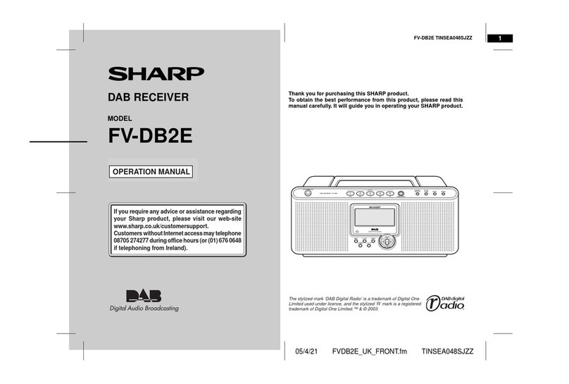
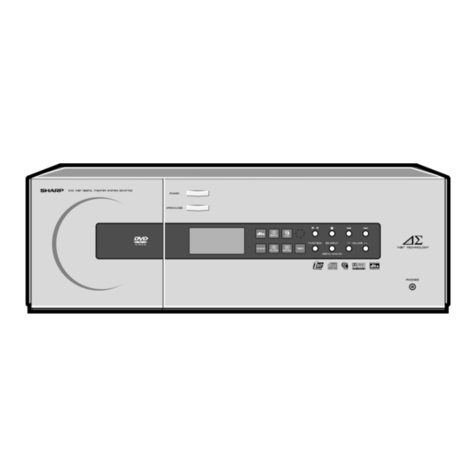
Sharp SC-103H User manual

==
Service
MODELS
SC-103H
CP-108H
CONTENTS
AS
BSTAT
TIC
ATH
COINS
ct
arses
boss
egies
aa
asst
saad
lest
planncaoainute
gates
oan
ge
atte
asia
te
2
DUS
ASSENMEL
Yucca
tees
inarcaeaie
ie
ates
asia
eee
deems
non
retin
arioadiominneatn
de
aaelementaldee
3
(PEA
ENN
MMOD
ES
eS
cece
iced
ae
Reve
cia
ta
td
tg
cliche
hae
Slaten
besinea
aca
ehncal
aaa
3
MECHANISM:
ADIUSTMENT
”
°aiccasssteuctantiuiuunetieienedascebietd
ele
I
goaaattte
st
aeieaaagnignnedmmammmiennals
7
ELECTRICAL
MEASUREMENT
<0
ictstacciescleenutae
tgs
iiss
camer
Satatiale
ete
etal
pthnnangte
Resadneniia
12
ATAGNIMEN
TD
INSTRUCTIONS:
OF
TRIN
ERS
:s.2sG:
sista
hisereseas
Hind
asnapaeclhased
xateatc
aces
eSietadalacsatlasa
tobieeaetnaeeeshdaa
ech
21
TROUBWE,
SHOOTING
CHART
5cse55sierscsay
se
discesaediastuprvses
eran
tndtuleactrtootas
ison
eSiasee
amen
naka
asst
ReSaeaed
caveat
26
GRBINGT
EXPLODED
VIEW
suintncaeenrcitendael
a
chalh
patie
iad
ans
date
anal
umonnneanmacacniagn
37,
33
MECHANISM
EXPLODED:
TOP:
VIEW
ozssassccs
aieccacanssliestanmasswcatpnnahaqastiresstetauigectbithaalit
oaceaks
artis
2s
aascenaadasgeanentene
39
MECHANISM
EXPLODED:
BOTROM
VIEW
joccicna
28d.
snarsalinnnnanichotua
ent
Ganda
aan
Mel
antatet
40
‘PRINTED
CIRCUIT
BOARD
VIEW
SCHEMATIC
DIAGRAM
-ahs.ctui2055
dav
toansaspteesazecnni
cin
Gi
tence
mental
nnaeinainigviens
BEARS
EES
Bee
sch
watt
hse
lacay
a
decedent
es
amccan
esi
UR
bape
beatae
Sete
ans
aCe
Sie
nA
this
47-3
SHARP
CORPORATION
oSAKA,
JAPAN
ELECTRICAL
SPECIFICATIONS
Circuit:
.
Semiconductors:
Power
Source:
Power
Consumption:
Speakers:
Dimensions:
(S§C103H)
(CP-108H)
Weight:
FM
SECTION
Frequency
Coverage:
Maximum
Sensitivity:
IF
Rejection:
Image
Rejection:
Frequency
Response:
Harmonic
Distortion:
Signal
to
Noise
Ratio:
FM
STEREO
SECTION
Stereo
Separation:
Stereo
Indicator
Lighting
Level:
Harmonic
Distortion:
Signal
to
Noise
Ratio:
AM
SECTION
Frequency
Coverage:
Maximum
Sensitivity:
IF
Rejection:
Image
Rejection:
AGC
Figure
of
Merit:
Band
Width:
Harmonic
Distortion:
FM/AM
2:-band
superheterodyne
system
stereo
tuner-amplifier
with
FM
multiplex
circuit
with
AFC
and
4
track
cassette
tape
recorder
and
2
way
speaker
system
31-transister.
J-FET.
1-IC.
110/220/240V,
50Hz
60
watts
Woofer
6-1/2"
x
2
Tweeter
1-5/8"
x
2
20-3/4"(W)x10-1/2"(D)x5-1/4"(H)
9-3/4"(W)x5-1/2"(D)x13-11/16"(H)
(SC103H)
=
15.2Ibs
(CP-108H)
4.2Ibs
x
2
15-diode
88
—
106MHz
1.6uV
70
dB
48
dB
70
—
10kHz
1%
45
dB
35
dB
10uV
1%
45
dB
520
~-
1,620kHz
130nV/m
30
dB
40
dB
$0
dB
5.5kHz
2%
AUDIO
SECTION
Total
Peak
Music-Power
Output:
Distortion
at
500mW:
Frequency
Response:
Hum
and
Noise
Level:
Sensitivity
for
Rated
Output:
Channel
Separation:
Tone
Characteristics:
20W
0.5%
40Hz
~
22kHz
Residual
Volume
3mV
Maximum
Volume
Phono
MM
60mV
Tape
60mV
Phono
M.M.
ImV
50
dB
Bass
Boost
at
100Hz
+8
dB
Cut
at
100Hz
-11dB
Treble
Boost
at
10kHz
+8dB
Cut
at
10kHz
~15
dB
TAPE
RECORDER
SECTION
Type:
Tape:
Tape
Speed:
Record/Playback
Time:
Recording
System:
Erasing
System:
Wow
&
Flutter:
Fast
Forward
&
Rewind
Time:
Frequency
Response:
Distortion:
Signal
to
Noise
Ratio:
Channel
Separation:
Erase
Ratio:
Input
Circuitry:
Sensitivity
&
Input
Impedance:
MIC
Line
4-track
2-channel
stereo
cassette
tape
recorder
Philips
type
compact
cassette
tape
1-7/8
ips
60
minutes
(C-60)
AC
bias
53.5kHz
AC
erasing
0.45%
weighted
peak
70
seconds
(C-60)
40Hz
to
12,000Hz
1.6%
46
dB
35
dB
65
dB
MIC
x
2(microphone
impedance
5002)
DIN-TYPE
0.1mV,
@47KQ
impedance
50mV,
@220KQ
impedance
Figure
1
DISASSEMBLY
2

DISASSEMBLY
CHASSIS
REMOVAL
(Refer
to
Figure
1)
1.
Disconnect
all
leads
connected
to
the
back
of
the
set.
2.
Remove
7
screws
(1)
retaining
the
chassis
(2).
3.
Gently
pull
forward
the
panel
(3)
and
chassis
from
the
cabinet
(4).
FRONT
PANEL
REMOVAL
_
1.
Remove
the
cabinet
as
described
in
Chassis
Removal.
2.
Remove
8
knobs
(5,6,7,8)
from
front
of
the
panel.
3,
Remove
9
screws
(9)
retaining
the
front
panel.
4.
Gently
pull
out the
panel
while
holding
both
sides.
Figure
2
DIAL
CORD
STRINGING
OPERATING
MODES
1.
STOP
Mode
YS
LY
@
ots
—
:
ff
yO
ice
O)
eal
(CO)
iC
g
zor,
4
Figure
3

iE
6
@|
(UE
PRE
Lot
edi
PYF
brats:
done
=,
+
=
——————
(
EA
b
i:
Mode
ERS;
a9,
:
ote
foe
O40
oe
=
Fp
@
Cy
Fale.
«
igstaue
ee
Sad
‘
f
=
2
"Ir
fo
of
nfm
mfri_o
i
frm
mfr
1)
conan
8,
Figure
7

Ne
‘a
6
eee
ca
Ss
LE
UNNAA
CO
~
a
ata
rae
ne:
BSS
-
f
25
OF
K
=
q
ms
@
a
=
Ww
CE
}
x
It
ES
st
{
SA
q
Figure
10
Figure
9
|
et
eta
pa
v
ts
eS
a
O
One
®
Oz
ec
eas
(©)
OFS
i.
fr
f
:
“han
1)
‘dad
ge

AST
FWD
Mode
NA,
Se
ee
fot
==
8
eo
ge
aR
gs
9
ely
2)
=
CcCOsc
6
<Ko
©
iro?
tr
a
om
ru,
pee
7.
PAUSE
Mode
AS
BESO
o{
((
—
off
CG,
Ors
©

1.
MECHANISM
ADJUSTMENT
AUTOMATIC
SHUT-OFF
MOTION
ADJUSTMENT
(Refer
to
Fig.
17
and
Fig.
18)
Sic
ADJUSTING
SCREW--(A)
or
veal)
[Sy
18+02m
(5/64"
+1/64")
=)
Figure
17
Adjust
the
position
of
the
electromagnet
by
using
a
thickness
gauge
so
that
a
distance
becomes
approximately
1.8+0.2mm(5/64"41/64")in
STOP
mode,
as
shown
in
Fig.
17.
Adjust
the
nut
so
that
clearance
between
STOP
lever
(081)
and
(082)
becomes
0.1
to
0.3mm
(1/128"~1/64").
FLYWHEEL
THRUST
CLEARANCE
ADJUSTMENT
(Refer
to
Fig.
19)
THRUST
ADJUSTING
SCREW
0.1~O.3mm
(I/128°~1/64")
Figure
19

3.
MOTOR
SWITCH
POSITION
ADJUSTMENT
(Refer
to
Fig.
20)
it
SW3
~ADJUSTMENT
POINT
Figure
20
4.
PRESSURE
ROLLER
ADJUSTMENT
(Refer
to
Fig.
21)
READING
STOPPER
CAPSTAN
SHAFT
275t
259r
PRESSURE
(9.7+0.880z)
GAUGE
Figure
21
1)
Adjust
the
pressing
force
of
the
pressure
roller
(101)
to
the
capstan
shaft
in
PLAY
mode.
2)
Read
the
value
of
pressing
force
when
the
pressure
roller
(101)
moves
off
the
capstan
shaft.
3)
At
the
time,
in
PLAY
mode
check
that
clearance
between
the
pressure
roller
(101)
and
the
stopper
is
around
0.5mm
(1/32”).
5.
TURNTABLE
DRIVING
PULLEY
PRESSURE
ADJUSTMENT
(Refer
to
Fig.
22)
ADJUSTMENT
HOLE
PLAY
Mode
,
096
(1.7
740.35
0z)
TENSION
GAUGE
(O~I100g)
(0
~350z)
Figure
22
1)
Measure
the
pressing
force,
hooking
a
tension
gauge
on
the
slip
roller
lever
(083).
2)
Read
the
pressing
force
when
the
take-up
turntable
(108)
stops.
8

6.
FAST
FWD
ROLLER
PRESSURE
ADJUSTMENT
(Refer
to
Fig.
23)
READING
[ste
|
(6.35
+1060z)
TENSION
GAUGE
toes
O-~100z
068
Figure
23
1)
Hook
a
tension
gauge
on
A
part
of
FAST
FWD
roller
(085)
in
FAST
FWD
mode
and
read
the
tension
gauge
when
the
take-up
turntable
(108)
stops.
Adjustment
is
made
by
bending
the
spring
(161).
7.
REWIND
ROLLER
PRESSURE
ADJUSTMENT
(Refer
to
Fig.
24)
TENSION
GAUGE
(0~100g)
(0
~350z)
Figure
24
1)
Set
a
tension
gauge
at
A
part
of
the
REWIND
roller
lever
(086)
in
REWIND
mode
and
read
the
tension
gauge
when
the
supply
turntable
(101)
stops..
Adjust
the
tension
by
the
spring
(159).
8.
BRAKE
LEVER
ADJUSTMENT
(Refer
to
Fig.
25)
088
ADJUSTMENT
SCREW
108
107
Figure
25
1)
Check
that
the
brake
lever
(088)
is
pressed
against
the
turntables
(107
&
108)
in
STOP
mode
and
that
the
brale
lever
(088)
is
apart
at
the
same
distance
from
the
turntables
(107
&
108)
in
PLAY,
FAST
FWD
and
REWIND
moks.
Adjust
it
by
the
retaining
screw.

9.
SUB-CHASSIS
STROKE
ADJUSTMENT
(Refer
to
Fig.
26)
155
ADJUSTMENT
SCREW
CASSETTE
HOLD
PIN
Figure
26
1)
Adjust
the
sub-chassis
adjusting
bracket
(155)
so
that
the
long
hole
of
the
sub-chassis
(058)
is
pressed
against
the
cassette
hold
pin
in
PLAY
mode
and
also
in
STOP
mode.
10.
PAUSE
MECHANISM
ADJUSTMENT
(Refer
to
Fig.
27
and
Fig.
28)
lol
;
na
SHAFT
10)
.omm(
1/32")
Figure
27
Figure
28
1)
Depress
the
PAUSE
button
in
PLAY
mode
and
check
that
clearance
between
the
pressure
roller
(101)
and
the
capstan
shaft
is
over
0.5mm
(1/32”).
Adjust
it
by
bending
A
part
of
the
pause
operating
lever
(072).
2)
After
adjustment,
depress
only
the
PAUSE
button
and,
in
PLAY
mode,
check
that
clearance
between
the
pressure
roller
lever
(101)
and
B
part
of
the
pause
operating
lever
(072)
is
over
1mm
(3/64").
3)
Adjust
it
by
bending
C
part
so
that
the
take-up
turntable
(128)
and
the
pressure
roller
(101)
simultaneously
stop
when
PAUSE
button
is
depressed
in
PLAY
mode.
4)
Disengage
PAUSE
button
and
check
that
clearance
at
C
part
is
over
Imm
(3/64”)
in
PLAY
mode.

11.
TRANSPORT
POWER
SWITCH
(SW-5
SW-6)
ADJUSTMENT
(Refer
to
Fig.
29)
1)
For
SW-5,
check
that
A
and
Bare
in
contact
with
each
other
but
C_
is
apart
in
STOP
mode
and
that
A
and
C
are
in
contact
but
Bis
apart
in
PLAY,
FAST
FWD,
REWIND
modes.
2)
For
SW-6,
check
that
D
and
E
are
in
contact
with
each
other
in
PAUSE
mode
and
apart
when
PAUSE
button
is
disengaged.
3)
Adjust
it
by
the
retaining
screw.
SW6
O72
SW5
O74
Figure
29
12,
TORQUE
CHECK
(Refer
to
Fig.
30)
DIAL
TORQUE.
GAUGE
TORQUE
(0~150g-cm)
PLAY
mode
45+15g.cm
(6.4742.150z-inch
)
FAST
FWD
mode
80+£20g-cm
(11.5+2.87
02-inch
)
ae
REWIND
mode
100420g.cm
(14.4+2.87
0z-inch
)
LJ
Stop
the
motion
of
the
revolving
turntable
by
tightening
Dial
Torque
Gauge,
and
then
loosen
the
Gauge
gradually
in
the
direction
of
turntable
revolution.
Read
the
gauge
value
when
the
turntable
has
begun
rotating.
(
108
107
Figure
30
13.
BACK
TENSION
TORQUE
CHECK
(Refer
to
Fig.
31)
TORQUE
PLAY
mode
less
than
18-cm
(0.14
oz.inch
)
REWIND
mode
less
than
6g.cm
(0.71
oz-inch
)
MEASURING
REEL
TENSION
GAUGE
(O~I0g)
(0~0,350z)
TURNTABLE
(iO7
&
108)
Figure
31
11

14.
CASSETTE
HOLDER
FALL
TIME
ADJUSTMENT
(Refer
to
Fig.
32)
1)
Check
that
the
cassette
tape
exact-
ly
falls
into
the
cassette
holder
(112)
when
inserted.
For
adjustment,
refer
to
the
figure.
\
075
ADJUSTING
SCREW
Figure
32
ELECTRICAL
MEASUREMENT
SPECIAL
EQUIPMENT
REQUIRED
The
following
items
will
be
required
for
performing
electrical
checks
and
adjustments:
1.
DC
constant-voltage
power
source
(DC
20.0V)
DC
voltmeter
(DC
20V)
V.T.V.M.
Frequency
counter
Signal
generator
Attenuator
Distortion
meter
Test
tape
(MTT-113,
6.3kHz
recorded)
Oscilloscope
8
ohm
dummy
resistor
(5%,
10W)
Test
tape
(MTT-112,
333Hz
recorded)
Test
tape
(MTT-117A
63Hz,
1kHz,
8kHz
recorded)
Blank
tape
AC
ammeter
Band
Pass
Filter
(1
kHz)
CPN
ANAwWD
eRe
PP
Pe
WRoONES
—_
POWER
AMPLIFIER
CHECK
(Refer
to
Fig.
33)
1)
Set
Mode
Selector
Switch
(SW-8)
at
“CASSETTE
PLAY”.
2)
Set
VOLUME
Control
(R207,
R208),
RECORD
MONITOR
VOLUME
Control
(R213,
R214)
in
the
minimum
position,
and
BASS
Control
(R209,
R210)
and
TREBLE
Control
(R211,
R212)
in
the
central
position.
3)
Connect
DC
constant
voltage
power
source
(DC
20.0V)
to
the
power
lead
wire
of
main
amplifier.
4)
Connect
PLUS
side
of
DC
voltmeter
to
TP101
(TP102)
and
MINUS
side
to
TP2.
Adjust
R307
(R308)
so
that
the
voltmeter’s
reading
becomes
10.0V.
5)
-Connect
PLUS
side
of
DC
voltmeter-to
TP103
(TP104)
and
MINUS
side
to
TP105
(TP106).
Adjust
R317
(R318)
so
that
voltmeter’s
reading
becomes
20mV.
12

Lee
C3
(a7
OuF
TPIOG
TPL
(TPIS
eps)
sm,
yu
eu
470uF
TPIO4
Figure
33
2.
RECORD
AMPLIFIER
BIAS
OSCILLATOR
CHECK
(Refer
to
Fig.
34)
RECORD
mode
Oscilloscope
R/P
HEAD
Frequency
Counter
Figure
34
Set
Mode
Selector
Switch
(SW-8)
at
“CASSETTE
PLAY”.
Set
the
unit
at
RECORD
mode.
Shift
R.LF.
Switch
(SW-4)
to
“A”.
Connect
V.T.V.M.
to
Test
Point
(R5,
R6).
Adjust
Semi-variable
resistor
(R409,
R410)
so
that
VTVM’s
reading
becomes
50mV.
Adjust
Oscillator
Coil
(L401)
so
that
the
frequency
counter’s
reading
becomes
53.5kHz+1.5kHz.
After
checking
bias
frequency,
re-check
for
the
item
5.
Then
shift
R.I.F.
switch
(SW-4)
to
“B”
and
check
that
bias
frequency
becomes
52.25kHz+10%.
13

3.
ERASE
VOLTAGE
CHECK
(Refer
to
Fig.
35)
Oscilloscope
RECORD
mode
V.T.V.M
ERASE
HEAD
Figure
35
1)
Set
Mode
Selector
Switch
(SW-8)
at
“CASSETTE
PLAY”.
2)
Then
set
the
unit
at
RECORD
mode.
3)
Set
R.ILF.
Switch
(SW-4)
at
“A”.
4)
Connect
VTVM
to
Resistor
(R408).
5)
It
is
normal
if
VTVM’s
reading
is
then
over
55mV.
4.
LEVEL
METER
SENSITIVITY
CHECK
(Refer
to
Fig.
36)
Oscilloscope
CR.
OSC
V.T.V.M
RECORD
mode
R/P
HEAD
Attenuater
—-l0dB
100
ohm
Figure
36
1)
Set
Mode
Selector
Switch
(SW-8)
at
“CASSETTE
PLAY”.
2)
Set
RECORD
MONITOR
VOLUME
Control
(R213,
R214)
in
the
maximum
positions,
and
BASS
Control
(R209
R210)
and
TREBLE
Control
(R211,
R212)
in
the
central
positions.
3)
Remove
the
ground
lead
of
bias
circuit
at
main
amplifier
and
stop
bias
oscillation.
4)
Set
the
unit
at
RECORD
mode.
5)
Input
-10dB,
1kHz
signal
to
LINE
IN
Jack
(SO701,
SO702)
and
adjust
VOLUME
Control
(R207,
R208)
so
that
voltage
‘at
both
ends
of
resistor
(R5,
R6)
becomes
3.5mV.
6)
Adjust
Semi-variable
resistor
(R119,
R120)
so
that
LEVEL
meter
indicates
OVU.
’
5.
RECORD
AMPLIFIER
SENSITIVITY
CHECK
(Refer
to
Fig.
37)
cCR.OSC
KHz
RECORD
mode
Attenuater
MIC
or
LINE
iN
Figure
37
14

Set
RECORD
MONITOR
VOLUME
Control
(R213,
R214)
in
the
maximum
position,
and
BASS
Control
(R209,
R210)
and
TREBLE
Control
(R211,
R212)
in
the
central
positions.
Set
VOLUME
Control
(R207,
R208)
in
the
maximum
position.
Set
the
unit
at
RECORD
mode.
Remove
the
ground
lead
of
bias
circuit
at
the
main
amplifier
and
stop
bias
oscillation.
Input
1kHz
signal
to
MICROPHONE
Jack
(J701,
J702).
Microphone
sensitivity
is
normal
if
attenuator’s
reading
is
within
the
range
of
-76
dB
to
~84
dB
when
LEVEL
meter
indicates
OVU.
Do
the
same
for
LINE
IN
Jack
(SO701)
as
did
for
microphone.
LINE
IN
sensitivity
is
normal
if
attenuator’s
reading
is
within
-22
dB
to
-30
dB.
Do
the
same
also
for
PHONO
Jack
(SO702)
as
did
for
microphone.
PHONO
sensitivity
is
normal
if
attenuator’s
reading
is
within
-56
dB
to
-64
dB.
NOTES:
1)
The
check
must
be
done
after
the
LEVEL
METER
Sensitivity
Check.
2)
Channel
to
channel
sensitivity
must
be
within
4
dB.
6.
RECORD
AMPLIFIER
FREQUENCY
CHARACTERISTIC
CHECK
(Refer
to
Fig.
38)
Oscilloscope
RECORD
mode
R/P
HEAD
Attenuater
LINE
IN
Jack
100
ohm
Figure
38
Set
Mode
Selector
Switch
(SW-8)
at
the
position
of
“CASSETTE
PLAY”.
Set
RECORD
MONITOR
VOLUME
Control
(R213,
R214)
in
the
maximum
position,
and
BASS
Control
(R209,
R210)
and
TREBLE
Control
(R211,
R212)
in
the
central
position.
Set
the
unit
at
RECORD
mode.
(Remove
the
ground
lead
of
bias
circuit
at
the
main
amplifier
and
stop
bias
oscillation.)
Input
-10
dB,
1kHz
signal
to
LINE
IN
Jack
(SO701)
and
adjust
VOLUME
Control
(R207,
R208)
so
that
voltage
at
both
ends
of
resistor
(R5,
R6)
becomes
ImV.
Then
change
the
oscillator
frequency
to
63Hz
and
8kHz
and
if
deviations
to
1mV
are
within
-1
dB
to
+3
dB
ad
+10
dB
to
+14
dB,
respectively,
the
RECORD
AMPLIFIER
frequency
characteristic
is
normal.
15

7.
PLAYBACK
AMPLIFIER
SENSITIVITY
CHECK
(Refer
to
Fig.
39)
Oscilloscope
Attenuater
R/P
HEAD
PLAY
BACK
mode
Speaker
Jack
Oummy
Figure
39
Set
Mode
Selector
Switch
(SW-8)
at
“CASSETTE
PLAY”.
Set
VOLUME
Control
(R207,
R208)
in
the
maximum
position,
BASS
Control
(R209,
R210)
and
TREBLE
Control
(R211,
R212)
in
the
central
position.
Set
the
unit
at
PLAYBACK
mode.
Disconnect
the
ground
lead
wires
(red)
of
Record/Playback
head
for
both
channels.
Input
1kHz
signal
between
head
terminal
and
lead
wire.
Connect
8
ohm
(£5%,
10W)
dummy
resistor
to
Speaker
Jack
(SO704,
SO705)
PLAYBACK
AMPLIFIER
sensitivity
is
normal
if
attenuator’s
reading
is
-78
dB
to
-84
dB
when
voltage
at
both
ends
of
resistor
becomes
3.3V.
8.
PLAYBACK
AMPLIFIER
FREQUENCY
CHARACTERISTIC
CHECK
(Refer
to
Fig.
39)
fBwWwWNnN
)
)
)
)
5)
6)
Set
Mode
Selector
Switch
(SW-8)
at
“CASSETTE
PLAY”.
Set
BASS
Control
(R209,
R210)
and
TREBLE
Control
(R211,
R212)
in
the
central
position.
Set
the
unit
at
PLAYBACK
mode.
Disconnect
the
ground
lead
wire
(red)
of
Record/Playback
head
for
both
channels.
Input
1kHz,
-81
dB
signal
between
head
terminal
and
lead
wire.
Connect
8
ohm
(45%,
10W)
dummy
resistor
to
speaker
jack
(SO704,
SO705)
and
adjust
VOLUME
Control
(R207,
R208)
so
that
voltage
at
both
ends
of
resistor
becomes
0.2V.
Then
change
the
frequency
of
signal
generator
to
63Hz
and
8kHz,
and
if
deviations
to
0.2V
are
+13.5
dB
to
+19.5
dB
and
+1
dB
to
-5
dB,
respectively,
the
PLAYBACK
AMPLIFIER
frequency
characteristic
is
normal.
16

9.
TONE
CHARACTERISTIC
CHECK
(Refer
to
Fig.
40)
Oscilloscope
V.T.V.M
CASSETTE
PLAY
mode
Speaker
Attenuoter
Jack
LINE
IN
Figure
40
1)
Set
Mode
Selector
Switch
(SW-8)
at
“LINE
IN”.
2)
Set
BASS
Control
(R209,
R210)
and
TREBLE
Control
(R211,
R212)
in
the
central
positions.
3)
Set
the
unit
at
RECORD
mode,
and
RECORD
MONITOR
VOLUME
Control
(R213,
R214)
in
the
maximum
position.
4)
Input
-10
dB,
1kHz
signal
to
LINE
IN
jack
(SO701)
and
connect
8
ohm
(45%,
10W)
dummy
resistor
to
Speaker
Jack
(SO704,
SO705)
and
adjust
VOLUME
Control
(R207,
R208)
so
that
voltage
at
both
ends
becomes
0.2V.
5)
Set
the
signal
of
signal
generator
at
125Hz
and
then
output
voltage
is
0
dB.
6)
At
the
time
it
is
normal
if
the
output
deviation
is
within
+5.5
to
+9.5
dB
when
BASS
Control
(R209,
R210)
is
set
at
BOOST
and
within
-7.5
to
-11.5
dB
when
it
is
set
at
CUT.
7)
Set
the
signal
of
signal
generator
at
8kHz
and
then
output
voltage
is
0
dB.
8)
It
is
normal
if
the
output
deviation
is
within
+5
to
+9
dB
when
TREBLE
Control
(R211,
R212)
is
set
at
BOOST
and
within
-10.5
to
-14.5
dB
when
it is
set
at
CUT.
10.
RECORD/PLAYBACK
HEAD
ADJUSTMENT
(Refer
to
Fig.
41)
1)
Set
Mode
Selector
Switch
(SW-8)
at
‘““CASSETTE
PLAY”.
2)
Set
BASS
Control
(R209,
R210)
and
TREBLE
Control
(R211,
R212)
in
the
central
positions.
3)
Connect
8
ohm
(45%,
10W)
dummy
resistor
to
Speaker
Jack
(SO704,
$O705)
and
VTVM
to
its
ends.
7

Insert
‘the
test
tape
(MTT-113,
6.3kHz
Recorded)
into
the
unit.
Set
the
unit
at
PLAYBACK
mode
and
adjust
Head
Azimuth
Adjustment
Screw
(A)
so
that
VIVM’s
reading
becomes
maximum
for
both
channel
1
and
channel
2.
NOTE:
Be
sure
to
apply
a
lock
paint
to
screw
(A)
after
adjustment.
Oscilloscope
V.T.V.M
PLAY
BACK
mode
R/P
HEAD
Test
Tape
Figure
41
11.
PLAYBACK
SENSITIVITY
VOLTAGE
CHECK
(Refer
to
Fig.
41)
12.
PL
1
ON
)
)
)
)
-
5)
Set
Mode
Selector
Switch
(SW-8)
at
“CASSETTE
PLAY”.
Set
VOLUME
Control
(R207,
R208)
in
the
maximum
position,
and
BASS
Control
(R209,
R210)
and
TREBLE
Control
(R211,
R212)
in
the
central
position.
Insert
the
Test
tape
(MTT-112,
333Hz
Recorded)
into
the
unit
and
set
it
at
PLAYBACK
mode.
Connect
8
ohm
(45%,
10W)
dummy
resistor
to
Speaker
Jack
(SO704,
SO705).
It
is
normal
if
voltage
at
both
ends
is
within
the
range
1.3V
~
2.5V.
Output
voltage
deviation
should
be
below
4
dB
for
both
channel
1
(left)
and
channel
2
(right).
NOTE:
The
check
must
be
done
after
RECORD/PLAYBACK
HEAD
ADJUSTMENT.
AYBACK
FREQUENCY
CHARACTERISTIC
CHECK
(Refer
to
Fig.
41)
Set
Mode
Selector
Switch
(SW-8)
at
“CASSETTE
PLAY”.
Set
BASS
Control
(R209,
R210)
and
TREBLE
Control
(R211,
R212)
in
the
central
position.
Insert
the
Test
tape
(MTT-117A,
63Hz,
1kHz,
8kHz,
Recorded)
into
the
unit
and
set
it
at
PLAYBACK
mode.
Connect
8
ohm
(45%,
10W)
dummy
resistor
to
Speaker
Jack
(SO704,
SO705)and
adjust
VOLUME
Control
(R207,
R208)
so
that
voltage
at
both
ends
becomes
0.5V
at
1kHz
and
0.5V
is
to
be
O
dB.
Then
playback
63Hz
and
8kHz,
and
check
output
deviation
to
1kHz.
PLAYBACK
frequency
characteristic
is
normal
if
deviation
is
-3
dB
to
+7
dB
at
63Hz
and
-5
dB
to
+5
dB
at
8kHz.
NOTE:
Demagnetize
Record/Playback
head
and
guide
before
checking.
18

13.
GENERAL
FREQUENCY
CHARACTERISTIC
CHECK
(Refer
to
Fig.
42)
Oscilloscope
Attenuater
V.T.V.M
CR.
OSC
—20dB
RECORD
mode
PLAY
BACK
mode
Speaker
iv
Jack
LINE
IN
Jack
Tape
Dummy
Figure
42
1)
Set
Mode
Selector
Switch
(SW-8)
at
“CASSETTE
PLAY”.
2)
Set
BASS
Control
(R209,
R210)
and
TREBLE
Control
(R211,
R212)
in
the
central
position.
3)
Set
RLF.
Switch
(SW-4)
at
“A”.
4)
Insert
the
cassette
tape
(not
recorded)
into
the
unit
and
set
it
at
RECORD
mode.
5)
Connect
8
ohm
(+5%,
10W)
dummy
resistor
to
Speaker
jack
(SO704,
SO705)
and
VTVM
to
the
ends.
6)
Input
-10
dB,
1kHz
signal
to
LINE
IN
Jack
(SO701).
Adjust
VOLUME
Control
(R207,
R208)
so
that
LEVEL
meter
indicates
OVU.
Henceforth,
make
the
input
level
-20
dB
and
record
1kHz,
63
Hz,
8kHz
signals.
14,
DIN
INPUT/OUTPUT
SENSITIVITY
CHECK
(Refer
to
Fig.43)
CR.OSC
V.T.V.M
(kHz
RECORD
mode
DIN
Sock
Attenuater
(Out
sri
~
26
dB
(A)
CR.OSC
V.T.V.M
Attenuater
—20dB
(B)
DIN
Socket
SPEAKER
(Input)
Socket
aon
Figure
43
(A)
1)
Set
Mode
Selector
Switch
(SW—8)
at
“CASSETTE
PLAY”.
2)
Insert
the
cassette
tape
into
the
unit
and
set
it
at
RECORD
mode.
3)
Input
-26dB,
1kHz
signal
to
LINE
IN
Jack
(SO701).
4)
Connect
50K
ohm
dummy
resistor
to
DIN
Socket
(Output
terminal).
It
is
normal
if
voltage
at
both
ends
is
within
the
range
-34
dB.
(B)
1)
Pull
out
Record
Monitor
control
knob.
2)
Input
1kHz
signal
to
DIN
Socket
(Input
terminal).
3)
Connect
8
ohm
(45%,
10W)
dummy
resistor
to
Speaker
jack
(SO704,
SO705).
and
VTVM
to
the
ends.
4)
Adjust,
Input
Signal
Level
so
that
V.T.V.M.
reading
3,3V.
Henceforth,
make
the
input
level
-20dB.
19

15.
CHANNEL
TO
CHANNEL
CROSSTALK
(Refer
to
Fig.
43)
Band
poss
Oscilloscope
cR.osc
Attenuoter
KHz
-10dB
RECORD
mode
PLAY
BACK mode
LINE
IN
Tape
Figure
44
1)
Set
Mode
Selector
Switch
(SW-8)
at
“CASSETTE
PLAY”.
2)
Set
BASS
Control
(R209,
R210)
and
TREBLE
Control
(R211,
R212)
in
the
central
positions.
3)
Set
R.I.F.
Switch
(SW-W)
at
“A”.
‘
4)
Insert
a
blank
cassette
into
the
unit
and
input
-10
dB,
1kHz
signal
to
LINE
IN
jack
and
record
only
in
one
channel
in
the
maximum
position
of
VOLUME
control
(R207,
R208).
5)
Playback
the
tape
after
recording
and
connect
8
ohm
dummy
to
Speaker
jack
(SO704,
SO705)
and
adjust
VOLUME
Control
so
that
voltage
at
both
ends
of
dummy
becomes
3.3V.
Henceforth,
output
voltage
through
1kHz
Band
Pass
Filter
is
to
be
0
dB.
6)
Adjust
VOLUME
Control
of
the
blank
channel
to
the
position
of
VOLUME
Control
of
the
recorded
channel
mechanically.
7)
Measure
voltage
at
both
ends
of
8
ohm
dummy
through
1kHz
Band
Pass
Filters.
It
is
normal
if
deviation
to
to
output
voltage
compared
with
the
above
5
is
over
25
dB.
16.
MEASUREMENT
OF
CURRENT
CONSUMED
(Refer
to
Fig.
44)
CR.
OSC
RECORD
mode
Attenuater
Speaker
Jack
8
ohm
Dummy
AC.
Ammeter
110/220/240V
50Hz
Figure
45
20
This manual suits for next models
1
Table of contents
Other Sharp Receiver manuals

Sharp
Sharp TU-AS2G User manual

Sharp
Sharp FV-DB1E User manual

Sharp
Sharp SD-HX500 User manual

Sharp
Sharp FV-DB2E User manual

Sharp
Sharp QT-CD121 User manual

Sharp
Sharp RT-203H User manual

Sharp
Sharp TU-AS1G User manual

Sharp
Sharp SD-SH111H User manual

Sharp
Sharp SD-PX2 User manual

Sharp
Sharp PN-ZB03H User manual