manuals.online logo
Brands
  1. Home
  2. •
  3. Brands
  4. •
  5. Sharp
  6. •
  7. Stereo System
  8. •
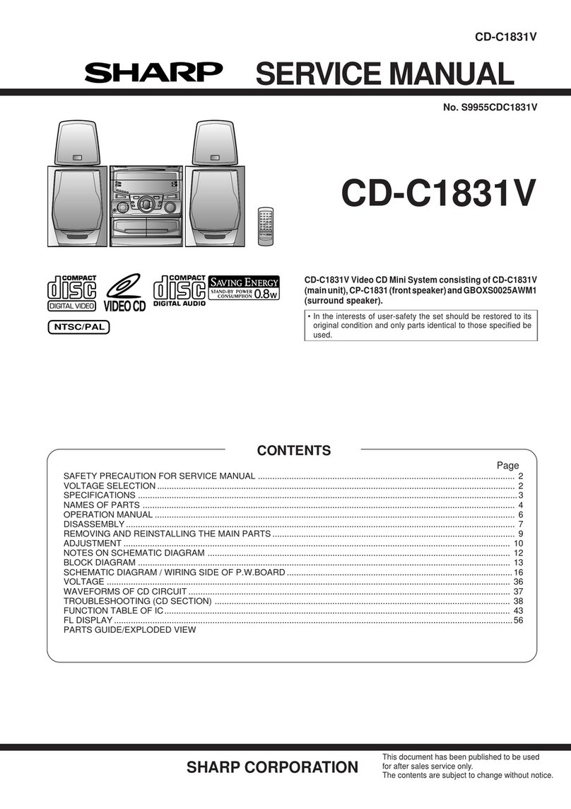
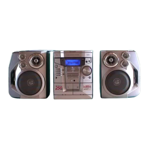
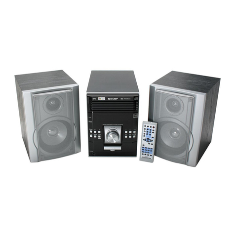
  9. Sharp CD-MPX100E User manual

Sharp CD-MPX100E User manual

Other manuals for CD-MPX100E

2

This manual suits for next models

1

Other Sharp Stereo System manuals

Sharp XL-DH320NH User manual

Sharp

Sharp XL-DH320NH User manual

Sharp XL-DV50H User manual

Sharp

Sharp XL-DV50H User manual

Sharp CD-DH790NH User manual

Sharp

Sharp CD-DH790NH User manual

Sharp XL-E2H User manual

Sharp

Sharp XL-E2H User manual

Sharp CD-XP120 User manual

Sharp

Sharp CD-XP120 User manual

Sharp GF-575Z User manual

Sharp

Sharp GF-575Z User manual

Sharp VZ-1600H(S) User manual

Sharp

Sharp VZ-1600H(S) User manual

Sharp CD-MPX200W User manual

Sharp

Sharp CD-MPX200W User manual

Sharp XL-35H User manual

Sharp

Sharp XL-35H User manual

Sharp CMS-R600X User manual

Sharp

Sharp CMS-R600X User manual

Sharp XL-E12H User manual

Sharp

Sharp XL-E12H User manual

Sharp DK-KP80PH User manual

Sharp

Sharp DK-KP80PH User manual

Sharp SD-NX10 User manual

Sharp

Sharp SD-NX10 User manual

Sharp MD X5 User manual

Sharp

Sharp MD X5 User manual

Sharp CD-SW340H User manual

Sharp

Sharp CD-SW340H User manual

Sharp CD-E250E User manual

Sharp

Sharp CD-E250E User manual

Sharp CD-XP160W User manual

Sharp

Sharp CD-XP160W User manual

Sharp CD-MPX100H User manual

Sharp

Sharp CD-MPX100H User manual

Sharp CD-BA2600H User manual

Sharp

Sharp CD-BA2600H User manual

Sharp XL-DK227NH User manual

Sharp

Sharp XL-DK227NH User manual

Sharp XL-MP131 User manual

Sharp

Sharp XL-MP131 User manual

Sharp QT-CD700W User manual

Sharp

Sharp QT-CD700W User manual

Sharp CD-BA250H User manual

Sharp

Sharp CD-BA250H User manual

Sharp CD-CH1500H User manual

Sharp

Sharp CD-CH1500H User manual

Popular Stereo System manuals by other brands

Sony HCD-VX88 Service manual

Sony

Sony HCD-VX88 Service manual

Philips MCM398D/12 user manual

Philips

Philips MCM398D/12 user manual

Sony CMT-SPZ90DB operating instructions

Sony

Sony CMT-SPZ90DB operating instructions

LG OM4560 owner's manual

LG

LG OM4560 owner's manual

JVC UX-G3 instructions

JVC

JVC UX-G3 instructions

Odys ODYS - LOOP instruction manual

Odys

Odys ODYS - LOOP instruction manual

Aiwa NSX-AJ700 Service manual

Aiwa

Aiwa NSX-AJ700 Service manual

Panasonic SC-AK100 operating instructions

Panasonic

Panasonic SC-AK100 operating instructions

Bogen NEARSCAPES 4.1 manual

Bogen

Bogen NEARSCAPES 4.1 manual

Panasonic SCPM29 - MINI HES W/CD PLAYER operating instructions

Panasonic

Panasonic SCPM29 - MINI HES W/CD PLAYER operating instructions

Meyer LD-3 operating instructions

Meyer

Meyer LD-3 operating instructions

THOMSON MIC302U manual

THOMSON

THOMSON MIC302U manual

Philips MCM530 Service manual

Philips

Philips MCM530 Service manual

Sony SS-CEP50 Service manual

Sony

Sony SS-CEP50 Service manual

Cetacea Sound CVS-II user guide

Cetacea Sound

Cetacea Sound CVS-II user guide

Sony MHC-V21D Service manual

Sony

Sony MHC-V21D Service manual

Denon UCD-250 Service manual

Denon

Denon UCD-250 Service manual

Exibel BDX600-UK user manual

Exibel

Exibel BDX600-UK user manual

manuals.online logo
manuals.online logoBrands
  • About & Mission
  • Contact us
  • Privacy Policy
  • Terms and Conditions

Copyright 2025 Manuals.Online. All Rights Reserved.

CD-MPX100E
SERVICE MANUAL
• Note for users in U.K.
Recording and playback of any material may require consent
which SHARP is unable to give. Please refer particularly to the
provisions of Copyright Act 1956, the Dramatic and Musical
Performers Protection Act 1956, the Performers Protection Acts
1963 and 1972 and to any subsequent statutory enactments and
orders.
SHARP CORPORATION
CONTENTS
Parts marked with " " are important for maintaining the safety of the set. Be sure to replace these parts with specified ones for
maintaining the safety and performance of the set.
This document has been published to be used
for after sales service only.
The contents are subject to change without notice.
CHAPTER 1. GENERAL DESCRIPTION
[1] Specifications.................................................1-1
[2] Names of parts...............................................1-2
CHAPTER 2. ADJUSTMENTS
[1] Mechanism section ........................................2-1
[2] Tuner section .................................................2-1
[3] TEST MODE..................................................2-2
[4] CD section......................................................2-3
CHAPTER 3. MECHANISM BLOCKS
[1] Caution on diassembly...................................3-1
[2] Removing and reinstalling the main parts........3-4
CHAPTER 4. DIAGRAMS
[1] Block diagrams............................................... 4-1
CHAPTER 5. CIRCUIT DESCRIPTION
[1] Notes on schematic diagram.......................... 5-1
[2] Types of transistor and LED........................... 5-1
[3] Waveforms of CD circuit ................................5-2
[4] Voltage...........................................................5-3
CHAPTER 6. CIRCUIT SCHEMATICS AND PARTS
LAYOUT
[1] Schematic diagram........................................6-1
[2] Wiring side of PWB......................................6-11
CHAPTER 7. FLOWCHART
[1] Troubleshooting.............................................7-1
CHAPTER 8. OTHERS
[1] Function table of IC .......................................8-1
[2] FL Display......................................................8-9
Parts Guide
DISPLAY
No. S3528CDMPX10H
In the interests of user-safety the set should be restored to its
original condition and only parts identical to those specified be
used.
MINI COMPONENT SYSTEM
CD-MPX100E
MODEL
CD-MPX100E Mini Component System consisting of
CD-MPX100E (main unit) and CP-MPX100H (speaker
system).
CD-MPX100E
– i –
[1] Safety precaution for service manual
Precaution to be taken when replacing and servicing the
Laser Pickup.
The AEL (Accessible Emission Level) of Laser Power Output
for this model is specified to be lower than Class 1 Require-
ments. However, the following precautions must be observed
during servicing to protect your eyes against exposure to the
Laser beam.
(1) When the cabinet has been removed, the power is turned
on without a compact disc, and the Pickup is on a position
outer than the lead-in position, the Laser will light for sev-
eral seconds to detect a disc. Do not look into the Pickup
Lens.
(2) The Laser Power Output of the Pickup inside the unit and
replacement service parts have already been adjusted prior
to shipping.
(3) No adjustment to the Laser Power should be attempted
when replacing or servicing the Pickup.
(4) Under no circumstances look directly into the Pickup Lens
at any time.
(5) CAUTION - Use of controls or adjustments, or performance
of procedures other than those specified herein may result
in hazardous radiation exposure.
[2] Important service notes (For U.K. only)
Before returning the unit to the customer after completion of a
repair or adjustment it is necessary for the following withstand
voltage test to be applied to ensure the unit is safe for the cus-
tomer to use.
Setting of Withstanding Voltage Tester and set.
Laser Diode Properties
Material: GaAIAs
Wavelength: 780 nm
Emission Duration: continuous
Laser Output: max. 0.6 mW
Set name set value
Withstanding Voltage Tester
Test voltage 4 kV DC
Set time 3 secs
Set current (Cutoff current) 3 mA
Unit
Judgment
OK: The "GOOD" lamp lights.
NG: The "NG" lamp lights and the buzzer sounds.
PROBE
AC
OUT
UNIT
SHORT-CIRCUIT
AC POWER
SUPPLY CORD
CONNECT THE PROBE
TO GND OF CHASSIS
SCREW
WITHSTANDING
VOLTAGE TESTER
CD-MPX100E
PRECAUTIONS FOR USING LEAD-FREE SOLDER
1. Employing lead-free solder
“All PWBs” of this model employs lead-free solder. The LF symbol indicates lead-free solder, and is attached on the PWBs and service manuals.
The alphabetical character following LF shows the type of lead-free solder.
Example:
Indicates lead-free solder of tin, silver and copper.
2. Using lead-free wire solder
When fixing the PWB soldered with the lead-free solder, apply lead-free wire solder. Repairing with conventional lead wire solder may cause damage
or accident due to cracks.
As the melting point of lead-free solder (Sn-Ag-Cu) is higher than the lead wire solder by 40 °C, we recommend you to use a dedicated soldering bit,
if you are not familiar with how to obtain lead-free wire solder or soldering bit, contact our service station or service branch in your area.
3. Soldering
As the melting point of lead-free solder (Sn-Ag-Cu) is about 220 °C which is higher than the conventional lead solder by 40 °C, and as it has poor
solder wettability, you may be apt to keep the soldering bit in contact with the PWB for extended period of time. However, Since the land may be
peeled off or the maximum heat-resistance temperature of parts may be exceeded, remove the bit from the PWB as soon as you confirm the steady
soldering condition.
Lead-free solder contains more tin, and the end of the soldering bit may be easily corrected. Make sure to turn on and off the power of the bit as
required.
If a different type of solder stays on the tip of the soldering bit, it is alloyed with lead-free solder. Clean the bit after every use of it.
When the tip of the soldering bit is blackened during use, file it with steel wool or fine sandpaper.
Be careful when replacing parts with polarity indication on the PWB silk.
Lead-free wire solder for servicing
Ref No. Parts No. Description
PWB-A 92LPWB6295MANS Main/Display/Headphones
PWB-B 92LPWB6295PWRS Power/Transformer
PWB-C 92LPWB6243CDUS CD MP3
– ii –
CD-MPX100E
1 – 1
AudioCD-MPX100EService ManualCD-MPX100EMarketE
CHAPTER 1. GENERAL DESCRIPTION
[1] Specifications
General
Amplifier
CD player
Tuner
Cassette deck
Power source AC 230 - 240 V, 50 Hz
Power consumption
50 W
Dimensions Width: 270 mm (10-5/8")
Height: 305 mm (12")
Depth: 342 mm (13-1/2")
Weight 6.1 kg (13.42 lbs.)
Output power MPO: 78 W (39W+39W)(10%T.H.D.)
RMS: 40 W (20W+20W)(10%T.H.D.)
RMS: 34 W (17W+17W)(0.9%T.H.D.)
Output terminals Speaker: 6 ohms
Headphones: 16 - 50 ohms
(recommended: 32 ohms)
Input terminals Video/Auxiliary (audio signal):
500 mV/47 k ohms
Type 3-disc multi-play compact disc player
Signal readout Non-contact, 3-beam semiconductor laser
pickup
D/A converter 1-bit D/A converter
Frequency response 20 - 20,000 Hz
Dynamic range 90 dB (1 kHz)
Frequency range FM: 87.5 - 108.0 MHz
AM: 522 - 1,620 kHz
Frequency response 50 - 14,000 Hz (normal tape)
Signal/noise ratio 55 dB (TAPE 1, playback)
50 dB (TAPE 2, recording/playback)
Wow and flutter 0.3 % (WRMS)
Type 2-way type speaker system
12 cm (4-3/4") Woofer with Piezo
Maximum input
power
40 W
Rated input power 20 W
Impedance 6 ohms
Dimensions Width: 200 mm (7-7/8")
Height: 305 mm (12")
Depth: 185 mm (7-1/4")
Weight 2.4 kg (5.3 lbs.)/each
CD-MPX100E
CP-MPX100H
FOR A COMPLETE DESCRIPTION OF THE OPERATION OF THIS UNIT, PLEASE REFER
TO THE OPERATION MANUAL.
Specifications for this model are subject to change without
prior notice.
CD-MPX100E
1 – 2
[2] Names of parts
Front panel
1. Disc Tray
2. Timer Set Indicator
3. Memory/Set Button
4. On/Stand-by Button
5. Display Button
6. Clock/Timer Button
7. Tuning Up Button
8. Tuning Down Button
9. Headphone Socket
10. Tape 2 Record Pause Button
11. Tape 1 Cassette Compartment
12. Equalizer Mode Select Button
13. Extra Bass/Demo Mode Button
14. Volume Up and Down Buttons
15. Disc Skip Button
16. Disc Tray Open/Close Button
17. Tape 2 Cassette Compartment
18. CD Button
19. Tape (1 2) Button
20. Disc or Tape Stop Button
21. Disc Track Down or Fast Reverse, Tape 2 Rewind,
Tuner Preset Down, Time Down Button
22. Tuner (Band) Button
23. Video/Auxiliary Button
24. Disc Play or Repeat, Tape Play Button
25. Disc Track Up or Fast Forward, Tape 2 Fast Forward,
Tuner Preset Up, Time Up Button
MINI COMPONENT SYSTEM CD-MPX100W
3
4
5
2
1
6
11
9
7
8
10
12
16
14
15
17
13
22
23
24
25
18
19
20
21
DISPLAY
CD-MPX100E
Display
1. Disc Number Indicators
2. CD Play Indicator
3. CD Pause Indicator
4. Memory Indicator
5. CD Repeat Play Indicator
6. WMA Indicator
7. CD Indicator
8. MP3 Indicator
9. Extra Bass Indicator
10. Tape Play Indicator
11. FM Stereo Mode Indicator
12. Daily Timer Indicator
13. FM Stereo Receiving Indicator
14. Tape 2 Record Indicator
15. Sleep Indicator
16. Timer Play Indicator
17. Timer Recording Indicator
Rear panel
1. AC Power Lead
2. FM/AM Loop Aerial Socket
3. Video/Auxiliary (Audio Signal) Input Sockets
4. Speaker Terminals
1
4
2
3
CD-MPX100E
1 – 3
Remote control
1. Remote Control Transmitter
2. Disc Number Select Buttons
3. MP3/WMA Display Button
4. Disc Clear/Dimmer Button
5. Memory Button
6. Disc Random Button
7. Tape 2 Record Pause Button
8. Disc Track Down or Fast Reverse, Tape 2 Rewind,
Tuner Preset Down, Time Down Button
9. Equalizer Mode Select Butto
10. Tuner (Band) Button
11. CD Button
12. On/Stand-by Button
13. Extra Bass Button
14. Clock/Timer Button
15. Disc Direct Search Buttons
16. Disc Pause Button
17. Disc Track Up or Fast Foward, Tape 2 Fast Forward,
Tuner Preset Up, Time Up Button
18. Disc/Tape Stop Button
19. Disc Play or Repeat/Tape Play Button
20. Video/Auxiliary Button
21. Tape (1 2) Button
22. Volume Up Button
23. Volume Down Button
1
2
4
7
8
9
10
11
12
13
15
16
17
18
19
20
21
23
3
5
6
14
22
CD-MPX100E
CP-MPX100H
1. Piezo
2. Woofer
3. Bass Reflex Duct
4. Speaker Wire
4
3
1
3
2
CD-MPX100E
2 – 1
AudioCD-MPX100EService ManualCD-MPX100EMarketE
CHAPTER 2. ADJUSTMENTS
[1] Mechanism section
• Driving Force Check
• Torque Check
• Tape Speed
[2] Tuner section
fL: Low-range frequency
fH: High-range frequency
• AM IF/RF
Signal generator: 400 Hz, 30%, AM modulated
•FMRF
Signal generator: 1 kHz, 40 kHz dev., FM modulated
•FMIF
Signal generator: 10.7 MHz, FM modulated
Torque Meter Specified Value
Play: TW-2111 Tape 1: Over 80 g
Tape 2: Over 80 g
Torque Meter Specified Value
Tape 1 Tape 2
Play: TW-2111 30 to 80 g.cm 30 to 80 g.cm
Fast forward: TW-2231 — 70 to 180 g.cm
— 70 to 180 g.cm
Test Tape Adjust-
ing Point Specified
Value Instrument
Connection
Normal
speed MTT-111 Variable
Resistorin
motor.
3,000 ±30 Hz
Speaker Speaker Ter-
minal (Load
resistance: 6
ohms)
Figure 1
Test Stage Frequency Frequency
Display Setting/
Adjusting
Parts
Instrument
Connection
AM IF 450 kHz 1,620 kHz T351 *1
AM Band
Coverage — 522 kHz (fL): T306
1.1 ±0.1 V *2
AM
Tracking 990 kHz 990 kHz (fL): T303 *1
*1. Input: Antenna Output: TP302
*2. Input: Antenna Output: TP301
TAPE MECHANISM
Tape
Motor
Variable Resistor in motor
Test
Stage Frequency Frequency
Display Setting/
Adjusting
Point
Instrument
Connection
FM Band
Coverage — 87.50 MHz T301 (fL):
1.3 V ±0.1 V *1
FM RF 98.00 MHz
(10-30 dB) 98.00 MHz L312 *2
*1. Input: Antenna Output: TP301
*2. Input: Antenna Output: Speaker terminal
Test
Stage Frequency Frequency
Display Setting/Adjust-
ing Point Instrument
Connection
IF 10.7 MHz 98 MHz T302 (Turn the
core of trans-
former T302
fully counter
clockwise)
*1
Figure 2 Adjustment Points
AM IF
FM RF
TP301
TP302
FM IF
T301
T302
R356
R381
T303
T306
IC301
L312
T351
CNP301
AM/FM LOOP ANTENNA
FM BAND
COVERAGE fL
AM BAND
COVERAGE fL
AM TRACKING
fL
MAIN PWB
1
CD-MPX100E
2 – 2
[3] TEST MODE
•Setting the test mode
Any one of test mode can be set by pressing several key as follows.
<X-BASS> + <CD> + <ON/STAND-BY> TEST: CD operation test.
Function: -CD test mode.
-Enter test mode.
CD TEST
OPEN/CLOSE operation is using manual.
<< >>, << >> buttons make pick's slide possible.
Do TOC IL. Do normal play.
When these following key is input
into PLAY key, track number can
be appoint directly.
<<PLAY>> key input. <<MEMORY>> key input.
<< 1 >> key: Track 4
<< 2>> key: Track 9
<< 3>> key: Track 15
<<STOP>> key input.
STOP
Laser ON.
<<MEMORY>> key input.
Tracking OFF play at that
specific point.
<<MEMORY>> key input.
Tracking ON play from
that specific point.
<<STOP>> key input.
STOP
IL isn't done
VOL Ñ Last memory
BAL Ñ CENTER
P.GEQ Ñ FLAT
X-BASS Ñ OFF
To cancel : Power OFF
Sliding the PICKUP with
<< >>, << >> button
must only be in STOP mode.
<<MEMORY>>
key input.
Adjustment result
automatically will
display as below.
for each 2 sec :
a) "FOFF_XX"
b) "TOFF_XX"
c) "TBAL_XX"
d) "TGAN_XX"
f) "FGAN_XX"
g) "RFLS_XX"
explanation:
a) Focus off set = "FOFF_XX"
b) Tracking off set = "TOFF_XX"
c) Tracking balance = "TBAL_XX"
d) Tracking Gain = "TGAN_XX"
f) Focus Gain = "FGAN_XX"
g) RF level shift = "RFLS_XX"
Adjustment result automatically will
display as below for each 2 sec :
a) "FOFF_XX"
b) "TOFF_XX"
c) "TBAL_XX"
d) "TGAN_XX"
f) "FGAN_XX"
g) "RFLS_XX"
<<MEMORY>> key input.
CD-MPX100E
2 – 3
[4] CD section
•Adjustment
Since this CD system incorporates the following automatic adjust-
ment functions, readjustment is not needed when replacing the
pickup. Therefore, different PWBs and pickups can be combined
freely.
Each time a disc is changed, these adjustments are performed
automatically. Therefore, playback of each disc can be performed
under optimum conditions.
Items adjusted automatically
1) Offset adjustment (The offset voltage between the head amplifier
output and the VREF reference voltage is compensated inside the
IC.)
* Focus offset adjustment
* Tracking offset adjustment
CD Error code description
* 'CHECKING'
If Error is detected, 'CHECKING' will be displayed instead of 'ER-
CD**' display. 'ER-CD**' display will only be displayed when error
had been detected for the 5 th times.
Standard Specification of Stereo System Error Message Display Contents
(*) CHECKING:
If CD changer mechanism error is detected, 'CHECKING' will be display instead of 'ER-CD**' display.
'ER-CD**' will only be display when CD changer mechanism error had been detected for the 5 th times.
Error Explanation
01 When Pickup set inner position, inner switch cannot detect
‘ON’ level for 10 secs.
10*
When tray moves to Open/Close, Open/Close switch can-
not detect ‘ON’ level for 7 secs.
When disc table rotate to target position.
Clamp switch cannot detect ‘ON’ level for 7 secs.
11* When disc table set to Disc1 position for 1 st time.
“CLAMP SW”, “DISC NO SW” and “OPEN/CLOSE” cannot
detect ‘ON’ level for 14 secs.
31 When it change to CD function, DSP cannot read initial
data.
Error Contents Display Notes
CD Pickup Mechanism Error. 'ER-CD**' 01: PU-IN SW Detection NG.
CD Changer Mechanism Error. 'ER-CD**' (*) 10: Changer Error.
11: Initial Error.
CD DSP Communication Error. 'ER-CD**' 31: DSP COMMUNICATION ERROR.
Focus Not Match. 'NO DISC'
TUNER PLL Unlock. PLL Unlock.
FM 87.5 MHz
CD-MPX100E
2 – 4
Speaker abnormal detection and +B PROTECTION display
In case speaker abnormal detection or +B PROTECTION had
occurred, it can be check by pressing 'POWER' and 'X-BASS' button
twice.
Display will show “S** B**”. S is referring to speaker abnormal detec-
tion and B is referring to +B PROTECTION. ** is in hex valve.
+B PROTECTION is condition when irregular process occur on power
supply line.
BEFORE TRANSPORYING THE UNIT
The following process need to be taken after set tapering/parts
replacement.
1. Press the ON/STAND-BY button to enter stand-by mode.
2. While pressing down the button and the X-BASS/DEMO button,
press the ON/STAND-BY button until “CLEAR AL” appears.
3. While pressing down the button and the X-BASS/DEMO
button, press the ON/STAND-BY button until “WAIT” →“FIN-
ISHED” appears.
4. Unplug the AC cord and the unit is ready for transporting.
/