Sharp SD-NX10W User manual

– 1 –
SD-NX10W
CONTENTS
Page
SAFETY PRECAUTION FOR SERVICE MANUAL ...........................................................................................................2
VOLTAGE SELECTION..................................................................................................................................................... 3
AC POWER SUPPLY CORD AND AC PLUG ADAPTOR ................................................................................................. 3
SPECIFICATIONS ............................................................................................................................................................. 3
NAMES OF PARTS ........................................................................................................................................................... 4
OPERATION MANUAL ...................................................................................................................................................... 7
DISASSEMBLY................................................................................................................................................................ 11
REMOVING AND REINSTALLING THE MAIN PARTS................................................................................................... 15
WIRING PROCESS DIAGRAM ....................................................................................................................................... 19
ADJUSTMENT ................................................................................................................................................................. 19
ERROR MESSAGE LIST................................................................................................................................................. 29
EEPROM WRITING PROCEDURE ................................................................................................................................. 30
DESCRIPTION OF CIRCUIT FOR 1-BIT UNIT ............................................................................................................... 32
TO CHECK AND CANCEL PROTECT CIRCUIT DETECTION LINE.............................................................................. 33
TEST MODE .................................................................................................................................................................... 34
NOTES ON SCHEMATIC DIAGRAM .............................................................................................................................. 41
TYPES OF TRANSISTOR AND LED............................................................................................................................... 41
BLOCK DIAGRAM ........................................................................................................................................................... 42
WIRING SIDE OF P.W.BOARD....................................................................................................................................... 49
SCHEMATIC DIAGRAM .................................................................................................................................................. 60
VOLTAGE ........................................................................................................................................................................ 74
WAVEFORMS OF 1-BIT CIRCUIT .................................................................................................................................. 75
WAVEFORMS OF MD CIRCUIT ..................................................................................................................................... 76
CD OPTICAL PICKUP LENS CLEANING ........................................................................................................................78
TROUBLESHOOTING ..................................................................................................................................................... 79
FUNCTION TABLE OF IC................................................................................................................................................ 83
FL DISPLAY..................................................................................................................................................................... 96
PARTS GUIDE/EXPLODED VIEW
SERVICE MANUAL
SHARP CORPORATION
No. S3119SDNX10W/
• In the interests of user-safety the set should be restored to its original
condition and only parts identical to those specified should be used.
This document has been published to be used
for after sales service only.
The contents are subject to change without notice.
The power of this unit is supplied from the amplifying unit via the
system connection cable. It does not operate by itself.
SD-NX10W
MODEL
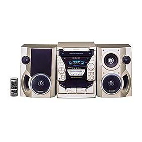
1-BIT DIGITAL AUDIO SYSTEM
SD-NX10W 1-bit Digital Audio System consisting of SD-NX10W
(MD/CD/TUNER unit), SD-NX10W (amplifier unit) and CP-NX10W
(speaker system).

SD-NX10W
– 2 –
SAFETY PRECAUTION FOR SERVICE MANUAL
The AEL (ACCESSIBLE EMISSION LEVEL) of the laser power output is less than class 1 but the laser component is capable of
emitting radiation exceeding the limit for class 1. Therefore it is important that the following precautions are observer during
servicing to protect your eyes against exposure to the laser beam.
(1)WhentheunitcasecoverisremovedandLOADINGSW(SW1932)isturnedonandthenPLAYSW(SW1934mechanismPWB)
is turned on in a few second.
The laser will light for several second to detect a disk.
(2) The laser power output of the pickup unit and replacement service parts are all factory preset before shipment.
Do not attempt to readjust the laser pickup unit during replacement or servicing.
(3) Under no circumstances stare into the pickup lens at any time.
(4) If laser optical unit becomes faulty, replace the complete laser optical unit.
(5) CAUTION-USE of controls or adjustments, or performance of procedures other than those specified herein may result in
hazardous radiation exposure.
Precaution to be taken when replacing and servicing the laser pickup.
The following precautions must be observed during servicing to protect your eyesvagainst exposure to the laser.
Warning of possible eye damage when repairing:
IftheACpowerplugisconnectedwhentheinnercoveroftheunitisremoved,thelaserwilllightupduringfocus access(about
1 second) (Fig. 2-1).
During this operation, the laser will leak from the opening between the magnetic head and cartridge holder (Fig. 2-2).
In order to protect your eyes, you must not look at the laser during repair.
Before repairing, be sure to disconnect the AC power plug.
Figure 2-1
Magnetic Head Optical Pickup
,,
Magnetic Head
Optical PickupSpindle Motor
Laser Beam
Cartridge Holder
Mechanism
Chassis
Figure 2-2
Laser Diode Properties
Material: GaAIAs
Wavelength: 785 nm
Pulse time:
Read mode:0.8 mW Continuous
Write mode:max 10 mW 0.5S
min cycle 1.5S
Repetition
CAUTION - INVISIBLE LASER RADIATION WHEN OPEN AND INTERLOCKS DEFEATED
AVOID EXPOSURE TO BEAM .
VARNING - OSYNLIG LASERSTR≈LNING NƒR DENNA DEL ƒR ÷PPNAD OCH SPƒRRAR
ƒR URKOPPLADE. STR≈LEN ƒR FARLIG.
ADVARSEL - USYNLIG LASERSTR≈LING N≈R DEKSEL ≈PNES OG SIKKERHEDSL≈S
BRYTES. UNNG≈EKSPONERING FOR STR≈LEN.
VARO! AVATTAESSA JA SUOJALUKITUS OHITETTAESSA OLET ALTTIINA
NƒKYMƒT÷N LASERSƒTEILYLLE. ƒLƒ KATSO SƒTEESEN.
VARNING - OSYNLIG LASERSTR≈LING NƒR DENNA DEL ƒR ÷PPNAD OCH SPƒRREN
ƒR URKOPPLAD. BETRAKTA EJ STR≈LEN.
ADVARSEL - USYNLIG LASERSTR≈LING VED ≈BNING N≈R SIKKERHEDSAFBRYDERE
ER UDE AF FUNKTION. UNDG≈UDSETTELSE FOR STR≈LING.

– 3 –
SD-NX10W
FOR A COMPLETE DESCRIPTION OF THE OPERATION OF THIS UNIT, PLEASE REFER
TO THE OPERATION MANUAL.
SPECIFICATIONS
SD-NX10W
Specifications for this model are subject to change without
prior notice.
CP-NX10W
Power source AC 110/127/220/230-240 V, 50/60 Hz
Power consumption 54 W
Dimensions MD/CD/tuner unit
Width: 318 mm (12-9/16")
Height: 210 mm (8-5/16")
Depth: 93 mm (3-11/16")
Amplifier unit
Width: 160 mm (6-5/16")
Height: 210 mm (8-5/16")
Depth: 136 mm (5-3/8")
Weight MD/CD/tuner unit
3.7 kg (8.2 lbs.)
Amplifier unit
3.8 kg (8.4 lbs.)
Input/output terminals MD/CD/tuner unit
Auxiliary input: 500 mV/47 kohms
Digital input (optical)
System output (RCA)
Line output: 500 mV/47 kohms
Headphones: 16 - 50 ohms (recommended: 32 ohms)
System control (SD-NX10W amplifier unit only)
Amplifier unit
System input (RCA)
Speakers; 6 ohms
System control (SD-NX10W MD/CD/tuner unit only)
Amplifier
CD player
MiniDiscGeneral
Tuner
Amplification system 64fs 1-bit switching
(Remarks:fs = 44.1 kHz)
Rated output power RMS: 50 W (25 W + 25 W) (10% T.H.D.)
A/D noise shaping 7th-order (delta - sigma) modulation
Type 1-disc slot-in type compact disc player
Signal readout Non-contact, 3-beam semiconductor laser pickup
D/A converter 1-bit D/A converter
Frequency response 20 - 20,000 Hz
Dynamic range 90 dB (1 kHz)
Type MiniDisc Recorder
Signal readout Non-contact, 3-beam semiconductor laser pickup
Rotation speed 400 - 900 rpm CLV, Approx.
Error correction ACIRC (Advanced Cross Interleave Reed-Solomon Code)
Quantization 20-bit linear (A/D converter)
Coding ATRAC (Adaptive TRansform Acoustic Coding), ATRAC3
Sampling frequency 44.1 kHz
Recording method Magnetic modulation overwrite method
Frequency response 20 - 20,000 Hz
D/A converter 1-bit D/A converter
Wow and flutter Unmeasurable (less than 0.001% W. peak)
Signal/noise ratio 95 dB (1 kHz)
Dynamic range 90 dB (1 kHz)
Audio channel Stereo: 2 channels (SP, LP2, LP4)
Monaural: 1 channel (MONO)
Frequency range FM: 88 - 108 MHz
AM: 531 - 1,602 kHz
Type 2-way type speaker system
3 cm (1-3/16") Tweeter
10 cm (4") Woofer
Maximum input power 50 W
Rated input power 25 W
Impedance 6 ohms
Dimensions Width: 187 mm (7-3/8")
Height: 423 mm (16-11/16")
Depth: 200 mm (7-7/8")
Weight 3.7 kg (8.2 lbs.)/each
VOLTAGE SELECTION
Before operating the unit on mains, check the preset voltage. If the voltage is different from your local voltage, adjust the voltage
as follows.
Turn the selector with a screwdriver until the appropriate voltage number appears in the window (110 V, 127 V, 220 V or 230-240 V AC).
QACCA0004AW00 QACCJ0006AW00
QACCB0008AW00
QACCE0007AW00
QACCL0002AW00
QPLGA0004AWZZ
AC POWER SUPPLY CORD AND AC PLUG ADAPTOR

SD-NX10W
– 4 –
NAMES OF PARTS
SD-NX10W
MD/CD/tuner unit front panel
1. CD Eject Button
2. CD Stop Button
3. CD Play/Pause Button
4. CD Fast Reverse/Tuning Down Button
5. CD Fast Forward/Tuning Up Button
6. MD Record Button
7. MD Stop Button
8. MD Play/Pause Button
9. MD Recording Level/MD Fast Reverse Button
10. MD +10 Track Up Button
11. MD Recording Level/MD Fast Forward Button
12. MD Eject Button
13. On/Stand-by Button
14. Tuner (Band) Button
15. Auxiliary/Demo Button
16. MD Record Mode Button
17. Erase Button
18. CD/MD Play Mode Select Button
19. Volume Up or Down Buttons
20. CD/MD Cover Open/Close Button
21. CD Compartment
22. MD Compartment
23. Timer Indicator
24. Sleep Indicator
25. Monaural Recording Indicator
26. Power Indicator
27. Stereo Recording Indicator
28. 2 times Long Recording (stereo) Indicator
29. 4 times Long Recording (stereo) Indicator
30. Remote Sensor
1 2 35 6 8 10 119
13 1415 16 17 18 19 20
21
23 24 25
2829
27
30
26
22
4712
Multi-function LCD display
1. Level Meter/Character Information/Frequency Indicator
2. Function Indicator
3. Record Indicator
4. CD/MD Play Indicator
5. Top Position Indicator
6. MD Record Pause Indicator
7. CD/MD Repeat Indicator
8. Surround Indicator
9. Random Play Indicator
10. Programme Play Indicator
11. Sound Synchronised Recording Indicator
12. Track Edit Indicator
13. TOC Indicator
14. FM Stereo Indicator
15. FM Stereo Mode Indicator
16. Sleep Indicator
17. Timer Play/Recording Indicator
2
1
3
4
5
6
9
11 12 13
14
15
16
17
8
10
7

– 5 –
SD-NX10W
MD/CD/tuner unit rear panel
1. Headphone Socket
2. Digital Input Socket
3. System Control Socket
4. System Output Sockets
5. Line Output Sockets
6. Auxiliary Input Sockets
7. Span Selector Switch
8. FM 75 Ohms Aerial Socket
9. Aerial Earth Terminal
10. AM Loop Aerial Terminal
13468910752
Amplifier unit front panel
1. Power Indicator
Amplifier unit rear panel
1. System Input Sockets
2. System Control Socket
3. Speaker Terminals
4. Cooling Fan
5. AC Input Socket
6. AC Voltage Selector
1
4
5
6
13
2

SD-NX10W
– 6 –
CP-NX10W
Remote control
1. Remote Control Transmitter
2. CD/MD Play Mode Select Button
3. MD Record Mode Button
4. On/Stand-by Button
5. MD Record Button
6. Top Position Button
7. Track Edit Button
8. Sound Synchronise Record Button
9. Volume Up or Down Buttons
10. CD/MD Fast Reverse, Tuning Down Button
11. Extra Bass Button
12. CD/MD Programme Button
13. Clear Button
14. Name/TOC-Edit Button
15. Timer/Delete Button
16. Time Button
17. Enter Button
18. MD Stop Button
19. MD Play/Pause Button
20. CD Stop Button
21. CD Play/Pause Button
22. Tuner (Band) Button
23. Auxiliary Input Button
24. Surround Button
25. CD/MD Fast Forward, Tuning Up Button
26. Preset Equalizer Button
27. Character Input/CD, MD, Tuner Direct Buttons
28. Display Button
29. Recording Level/Cursor/Tuner Preset Buttons
30. CD/MD Edit Buttons
1
2
3
4
5
6
7
8
9
10
11
12
13
14
15
16
17
*
*
*
*
*
*
*
*
*
*
18
19
20
21
22
23
24
25
26
27
28
29
30
*
*
*
*
*
*
Buttons with "*" mark in the illustration can be operated on the remote control only.
Other buttons can be operated both on the main unit and the remote control.
1. Speaker Grille
2. Tweeter
3. Woofer
4. Woofer
5. Bass Reflex Duct
6. Speaker Terminals 1
2
3
46
5

– 7 –
SD-NX10W
OPERATION MANUAL
Setting the Clock
In this example, the clock is set for 9:30 15. 02 '01 .
To confirm the time display:
[When the unit is in the stand-by mode]
Press the DISPLAY button on the remote control.
The time display will appear for about 5 seconds.
[When the power is on]
Press the TIMER/DELETE button.
Within 10 seconds, press the REC LEVEL/CURSOR or button.
The time display will appear for about 10 seconds.
Note:
The clock setting will be cleared when the unit is unplugged or the power failure
occurs.
To reset the clock:
Perform "Setting the Clock" from the beginning.
1
Press the ON/STAND-BY button to turn the power on.
2
Press the TIMER/DELETE button.
3
Within 10 seconds, press the REC LEVEL/CURSOR or button to
select the "TIME ADJUST".
4
Within 10 seconds, press the ENTER button.
5
Press the REC LEVEL/CURSOR or button to adjust the year,
and then press the ENTER button.
6
Press the REC LEVEL/CURSOR or button to adjust the month,
and then press the ENTER button.
7
Press the REC LEVEL/CURSOR or button to adjust the date,
and then press the ENTER button.
8
Press the REC LEVEL/CURSOR or button to adjust the hour,
and then press the ENTER button.
9
Press the REC LEVEL/CURSOR or button to adjust the minutes,
and then press the ENTER button.
The hour will not advance even if minutes advance from "59" to "00".
The clock starts from "0" second. (Seconds are not displayed.) The time display
will disappear after a few seconds.
Remote Control
Notes concerning use:
Replace the batteries if the operating distance is reduced or if the operation
becomes erratic. Purchase 2 "AA" size batteries (UM/SUM-3, R6, HP-7 or similar).
Periodically clean the transmitter on the remote control and the sensor on the ste-
reo system with a soft cloth.
Exposing the sensor on the stereo system to strong light may interfere with opera-
tion. Change the lighting or the direction of the stereo system.
Keep the remote control away from moisture, heat, shock, and vibrations.
Test of the remote control
Check the remote control after checking all connections have been made correctly.
Face the remote control directly to the remote sensor on the unit.
The remote control can be used within the range shown below:
Press the ON/STAND-BY button. Does the power turn on? Now, you can enjoy the
music.
Remote sensor
0.2 m - 6 m
(8" - 20')

SD-NX10W
– 8 –
System Connections
Setting the AC voltage selector
Check the setting of the AC voltage selector located on the rear panel before plug-
ging the unit into an AC socket. If necessary, adjust the selector to correspond to the
AC power voltage used in your area.
Turn the selector with a screwdriver until the appropriate voltage number
appears in the window (110 V, 127 V, 220 V or 230 V - 240 V AC).
Connecting the AC power lead
After making all connections, plug the unit. If you plug the unit first, the unit
will enter the demonstration mode.
Notes:
Plug the AC power lead into an AC socket, after any connections.
Unplug the AC power lead from the AC socket if the unit will not be in use for a pro-
longed period of time.
AC Plug Adaptor
In areas (or countries) where an AC socket as shown in illustration is used, con-
nect the unit using the AC plug adaptor supplied with the unit, as illustrated. The AC
plug adaptor is not included in areas where the AC wall socket and AC power plug
can be directly connected (see illustration ).
Note for users in Australia and New Zealand:
An AC plug adaptor is not supplied if the lead has an Australian Standard plug.
Setting the FM/AM span selector
The International Telecommunication Union (ITU) has established that member coun-
tries should maintain either a 100 kHz or a 50 kHz interval between broadcasting fre-
quencies of FM stations and 10 kHz or 9 kHz for AM station. The illustration shows
the 50/9 kHz zones (regions 1 and 3), and the 100/10 kHz zone (region 2).
Before using the unit, set the SPAN SELECTOR switch (on the rear panel) to the
interval (span) of your area.
To change the tuning zone:
1
Unplug the AC power lead from the AC socket.
2
Set the SPAN SELECTOR switch (on the rear panel) as follows.
For 50 kHz FM interval (9 kHz in AM) 50/9
For 100 kHz FM interval (10 kHz in AM) 100/10
3
Plug the AC power lead to the AC socket.
Caution:
This operation will erase all data stored in memory including clock, timer settings,
tuner preset, and CD or MiniDisc programme.

– 9 –
SD-NX10W
Troubleshooting Chart
Many potential "problems" can be resolved by the owner without calling a service
technician.
General
CD player
MiniDisc
Tuner
Remote control
Symptom Possible cause
"TIME ADJUST" appears when the
clock time is checked. Did a power failure occur? Reset the clock.
When a button is pressed, the unit
does not respond. Set this unit to the power stand-by mode and
then turn it back on.
No sound is heard. Is the volume level set to "0"?
Are the headphones connected?
Are the speaker wires disconnected?
The picture on the TV screen is dis-
torted. When a radio or TV which uses an indoor
aerial is placed near the unit, the picture on
the TV screen may be distorted or the radio
may not function properly.
It is recommended that you use an external
aerial.
Cannot adjust the volume. Is the sound connection lead connected to
the LINE OUT sockets on the MD/CD/tuner
unit? Set the unit to the stand-by mode and
connect the lead to the SYSTEM OUT sock-
ets.
Symptom Possible cause
Eventhoughadischasbeenloaded,
"CD NO DISC" or "Can't READ" is
displayed.
The disc is very dirty.
Is the unit located near excessive vibrations?
Has condensation formed inside the unit?
Playback does not start. The disc is loaded upside down.
Playbackstopsinthemiddleoris not
performed properly. The disc does not satisfy the standards.
The disc is distorted or scratched.
Playback sounds are skipped, or
stopped in the middle of a track. Is the unit located near excessive vibrations?
The disc is very dirty.
Has condensation formed inside the unit?
Symptom Possible cause
A recording cannot be made. Is the MiniDisc protected against accidental
erasure?
Did you try to make recording on a playback-
only MiniDisc?
Can you see the "DISC FULL" or "TOC
FULL" message in the display?
Eventhoughadischasbeenloaded,
"MD NO DISC" or "Can't READ" is
displayed.
The disc is very dirty.
Is the unit located near excessive vibrations?
Playback sounds are skipped. Has condensation formed inside the unit?
Symptom Possible cause
Radio makes unusual noise consec-
utively. The stereo system is placed near the TV or
computer.
FM/AM loop aerial is not placed properly.
Move the AC power lead away from the aeri-
al if located near.
The preset channel cannot be re-
called. Did a power failure occur?
Preset the channel again.
Symptom Possible cause
The remote control does not oper-
ate. Is the AC power lead of the stereo system
plugged in?
The battery polarity is not correct.
The batteries are dead.
Incorrect distance or angle.
Does the remote control sensor receive
strong light?
If trouble occurs (reset)
When this product is subjected to strong external interference (mechanical shock,
excessive static electricity, abnormal supply voltage due to lightning, etc.) or if it is
operated incorrectly, it may malfunction.
If such a problem occurs, do the following:
Unplug the power lead from the AC socket. Then, plug it in again and retry the
operation.
Caution:
This operation will erase all data stored in memory including clock, timer settings,
tuner preset, and CD or MiniDisc programme.
Condensation
Before transporting the unit
Remove the CD and MiniDisc from the unit. Your unit checks whether there are any
discs inside. "CD NO DISC" and "MD NO DISC" appear if no disc is inside. Then, set
the unit to the power stand-by mode. Carrying the unit with discs left inside can dam-
age it.
Sudden temperature changes, storage or
operation in an extremely humid environ-
ment may cause condensation inside the
cabinet (CD pickup, MD pickup, etc.) or on
the transmitter on the remote control.
Condensation can cause the unit to mal-
function. Ifthis happens, leave the power on
with no disc inthe unit until normal playback
is possible (about 1 hour). Wipe off any con-
densationonthe transmitterwitha softcloth
before operating the unit.
SD-NX10W
– 10 –
Error Messages
When an error message is displayed, proceed as follows:
Error messages Meaning Remedy
BLANK MD Nothing is recorded. (Neither
music nor disc name is re-
corded.)
Replace it with another disc.
Can't COPY You tried to record from a
copy prohibited CD. Replace the CD.
Can't EDIT A track cannot be edited. Change the stop position of the
track and then try editing it.
Can't READ* The disc is damaged. Replace it with another disc.
(*: Number or
symbol) TOC information cannot be
read. Erase the disc and try recording
again.
MiniDisc not specified.
Can't REC Recording cannot be per-
formed correctly due to vibra-
tion or shock in the unit.
Re-record or replace the Mini-
Disc.
Can't T REC Timer recording is impossible
or there is no available space
on the MD.
Replace it with another record-
able disc.
The disc is out of recording
space.
Can't WRITE The TOC information could
not be created properly due to
a mechanical shock or to
scratches on the disc.
Set this unit to the stand-by
mode and try to write the TOC
again. (Remove any source of
shock or vibration whilst writing.)
CD NO DISC A CD has not been loaded. Load a CD.
The CD data cannot be read. Reload the CD.
DISC FULL The disc is out of recording
space. Replace the disc with another
recordable disc.
EDIT OVER You chose 21 or more tracks
for track editing. Decrease the number of tracks.
Er - MD ** A MiniDisc is not working
properly. Press the MD button.
(**: Number or
symbol) Set this unit to the stand-by
mode and turn the power on
again.
Error messages Meaning Remedy
MD NO DISC A MiniDisc has not been load-
ed. Load a MiniDisc.
The MiniDisc data cannot be
read. Reload the MiniDisc.
NAME FULL The number of characters for
the disc name or track name
exceeds 40.
Shorten the disc or track name.
NOT AUDIO Thedatarecordedonthisdisc
is not audio data. Replace the disc.
PLAYBACK MD You tried to record on a play-
back-only disc. Replace it with another record-
able disc.
POWER ? A MiniDisc is not working
properly.
Set this unit to the stand-by
mode and turn the power on
again.
PROTECTED The disc is write protected. Move the write protection tab
back to its original position.
TEMP OVER The temperature is too high. Set this unit to the stand-by
mode and wait for a whilst.
TOC FORM ** TOC information recorded on
the MD does not match the
MiniDisc specifications or it
cannot be read.
Replace it with another disc.
(**: Number or
symbol) Erase the discand try recording
again.
TOC FULL There is no space left for re-
cording track numbers. Replace it with another record-
able disc.
TOC FULL 1 There is no space left for re-
cording character information. Replace it with another record-
able disc.
Erase the needless characters.
? MD DISC The data contains an error. Press the MD button.
MiniDisc not specified. Replace it with another disc.

– 11 –
SD-NX10W
1 Leg Cabinet 1. Screw ..................(A1) x5 11-1
2 Rear Panel 1. Screw ..................(B1) x9 11-1
2. Screw ..................(B2) x1
3
MD/CD Lid Cabinet/
1. Open it in the direction of 11-2
Loading Gear Ass'y
the arrow.
* (Note 1) 2.
Lid Cushion Cover ...
(C1) x2
3.
Screw Cover Sheet..
(C2) x1
4. Screw ................. (C3) x5
5. Rear Support Bracket
.................................(C4) x1
6. Socket ................ (C5) x3
4 Front Cabinet 1. Screw ................. (D1) x5 11-2
2. Socket ................ (D2) x2 11-3
3. Tip ...................... (D3) x1
5 Main PWB 1. Screw ..................(E1) x6 11-3
2. Socket .................(E2) x7
3. Flat Cable............ (E3) x3
6 MD/CD Block 1. Screw .................. (F1) x5 12-1
2. Socket ................. (F2) x2 12-2
7 Tuner Unit 1. Screw ................. (G1) x3 12-2
8 Jack PWB 1. Screw ................. (H1) x6 12-2
9 MD Sensor PWB 1. Screw .................. (J1) x1 12-3
10 OPEN/CLOSE 1. Screw ..................(K1) x1 12-3
Switch PWB
11 LED A/B PWB 1. Hook .................... (L1) x2 12-4
2. Screw .................. (L2) x4
12 Front Decoration 1. Screw ................. (M1) x8 12-4
Panel 2. Earth Plate ......... (M2) x1
13 Top Cabinet 1. Screw ................. (N1) x3 12-5
14
MD/CD Switch PWB
1. Screw ................(P1) x10 12-5
15 Socket PWB 1. Screw ................. (Q1) x2 12-6
16
CD Mechanism Ass'y
1. Screw ................. (R1) x4 12-6
17
MD Mechanism Unit
1. Screw ..................(S1) x4 12-6
18 MD Mechanism/ 1. Screw .................. (T1) x8 13-1
MD Main PWB 2. Flat Cable............ (T2) x3
* (Note 2) 3. Flexible PWB ...... (T3) x1
4. Socket ................. (T4) x2
DISASSEMBLY
STEP REMOVAL PROCEDURE FIGURE Figure 11-1
Caution on Disassembly
Follow the below-mentioned notes when disassembling
the unit and reassembling it, to keep it safe and ensure
excellent performance:
1. Take compact disc and minidisc out of the unit.
2. Be sure to remove the power supply plug from the wall
outlet before starting to disassemble the unit.
3.Takeoff nylon bandsorwire holderswheretheyneed to
beremovedwhendisassemblingtheunit.Afterservicing
theunit,be sure torearrangethe leads wheretheywere
before disassembling.
If the screw of the wrong length is applied on the MD
mechanism unit (screw for mounting parts to the MD
mechanism chassis), it may contact the optical pickup
and cause the unit to malfunction.
4. Take sufficient care on static electricity of integrated
circuits and other circuits when servicing.
SD-NX10W (MD/CD/TUNER UNIT)
* (Note 1)
Screws are covered. Remove the cushion covers first with a sharp-
ended stick and then screws.
Be careful not to damage them when removing. They will be reused.
* (Note 2)
After pulling out the optical pickup connector, wrap the tip of it with
conductivealuminium foilor theliketo protectthe opticalpickupfrom
the static electricity.
Figure 11-2
(A1)x5
ø3x10mm
(B1)x9
ø3x10mm
(B2)x1
ø3x8mm
Rear Panel
Front Cabinet
Leg Cabinet
(D1)x3
ø3x10mm
(C3)x1
ø3x10mm
(C3)x2
ø3x10mm
(C3)x2
ø3x10mm
(C1)x2
(D1)x2
ø3x10mm
Socket
PWB
Loading Gear
Ass'y
MD/CD Lid
Cabinet
(C2)x1
(C4)x1
(C5)x3 CD Mechanism
Ass'y
MD Mechanism
Unit Front
Cabinet
Figure 11-3
(E1)x6
ø3x8mm
(D2)x1
(E2)x2
Main PWB
Main PWB
Jack PWB
(E2)x1
(E3)x1
Main PWB
Jack PWB Jack PWB
(D2)x1
(E3)x1
(E3)x1
(D3)x1
(E2)x1
(E2)x1
(E2)x2

SD-NX10W
– 12 –
Figure 12-1
Figure 12-2
Figure 12-3
Figure 12-4
Figure 12-5
Figure 12-6
CD Mechanism
Ass'y
MD/CD
Block
MD Mechanism
Unit
(F1)x1
ø3x8mm
(F1)x1
ø3x8mm
(F1)x3
ø3x10mm
Tuner Unit
Jack PWB
(H1)x3
ø3x8mm
Lug
Wire
Lug Wire
(H1)x1
ø3x10mm
(H1)x2
ø3x10mm
(G1)x3
ø3x8mm
(F2)x1
(F2)x1
OPEN/CLOSE
Switch PWB
MD/CD Lid
Cabinet
MD Sensor
PWB
(J1)x1
ø2.6x8mm
(K1)x1
ø2.6x8mm
Front Cabinet
(M2)x1
Front
Decoration
Panel Lighting
Plate
LED B PWB
LED A
PWB
Lug Wire
Lug Wire
(M1)x1
ø3x6mm
(M1)x1
ø3x6mm
(L1)x1
(L1)x1
(M1)x6
ø3x6mm
(L2)x4
ø3x10mm
Front
Cabinet
Top
Cabinet
(N1)x3
ø3x10mm
(P1)x5
ø3x10mm
(P1)x5
ø3x10mm
CD Switch
PWB
MD Switch
PWB
Socket PWB
Lug Wire
MD Mechanism
Unit
CD Mechanism
Ass'y
(S1)x2
ø3x10mm
(Q1)x2
ø3x10mm (S1)x2
ø3x10mm
(R1)x2
ø3x10mm (R1)x2
ø3x10mm
MD/CD
Block Fram

– 13 –
SD-NX10W
Figure 13-1
Figure 13-2
Special driver
(Amplifier unit: aluminium decorative plate)
To prohibit users' disassembling the unit, special screws are
used to fix the decorative plate. A special driver is required.
Figure 13-4
Special driver bit
(Torque head: T8 type)
1 Leg Cabinet 1. Screw ..................(A1) x5 13-3
2 Rear Cabinet 1. Screw ................(B1) x11 13-3
3 Front Cabinet 1. Screw ................. (C1) x6 13-4
4 Rear Panel 1. Screw ................. (D1) x6 14-1
2. Socket ................ (D2) x1
5 1-Bit Amp Unit 1. Screw ..................(E1) x2 14-1
2. Socket .................(E2) x4
6 Terminal PWB 1. Screw .................. (F1) x2 14-2
2. Socket ................. (F2) x2
7 Power/Amp LED 1. Screw ................. (G1) x2 14-2
PWB 2. Socket ................ (G2) x2
8 Shield Cover 1. Screw ............... (H1) x12 14-3
2. Heat Sink.............(H2) x1
3.
1-Bit Amp Bracket....
(H3) x1
9 1-Bit Amp PWB 1. Screw .................. (J1) x4 14-4
STEP REMOVAL PROCEDURE FIGURE
SD-NX10W (AMPLIFIER UNIT)
Figure 13-3
(T2)x2
(T1)x1
ø
2x2mm
(T1)x1
ø
2x3mm
(T1)x1
ø
2x3mm
(T1)x1
ø
2x3mm
(T1)x1
ø
2x3mm
(T2)x1
(T4)x1
(T4)x1
(T1)x1
ø
2x3mm
(T1)x2
ø
1.7x3mm
Shield Case, Bottom
(T3)x1
Optical pickup
Flexible PWB (*1)
Pull
Pull
MD Main PWB
MD Mechanism
Shield Case, Side
Shield Case, Top
(*1) After pulling out the flexible
PWB for the optical pickup,
wrap its tip with conductive
aluminium foil or the like to
protect the optical pickup from
the static electricity.
(A1)x5
ø3x10mm Front Cabinet
Rear Cabinet
Leg Cabinet
(B1)x1
ø3x10mm
(B1)x3
ø3x10mm
(B1)x5
ø3x10mm
(B1)x1
ø3x8mm
(B1)x1
ø3x10mm
(C1)x2
ø3x8mm
(C1)x2
ø3x8mm
Front Cabinet
(C1)x2
ø3x10mm
Washer

SD-NX10W
– 14 –
Figure 14-1
Figure 14-2
Figure 14-4
Figure 14-3
(D1)x2
ø3x8mm
(D1)x1
ø3x10mm
(D1)x3
ø3x8mm
(E2)x1
(E2)x1
(E2)x1
(E2)x1
(D2)x1
(E1)x2
ø3x8mm
Power
PWB
Power
PWB
Terminal
PWB
Rear
Panel
1-Bit Amp
Unit
Power Trans
PWB
(G1)x1
ø3x10mm
(G1)x1
ø3x8mm
(F1)x2
ø3x8mm
(G2)x2 (F2)x2
Power
PWB
Terminal
PWB
Amp LED
PWB
Main Chassis
Power Trans
PWB
Power PWB
Terminal
PWB
(H1)x2
ø3x8mm
(H1)x1
ø3x6mm
(H1)x1
ø3x6mm
(H1)x1
ø3x6mm
(H1)x1
ø3x8mm
(H1)x4
ø3x8mm
(H1)x1
ø3x6mm (H1)x1
ø3x8mm
(H3)x1
(H2)x1
Washer
Washer
Shield
Cover
(J1)x4
ø3x10mm
1-Bit Amp PWB
1 Woofer 1. Leg Cushion ........(A1) x4 14-5
2. Screw ..................(A2) x4
3. Top Cover ...........(A3) x1
4. Front Panel .........(A4) x1 14-6
5. Screw ..................(A5) x8
2 Tweeter 1. Screw ..................(B1) x4 14-6
STEP REMOVAL PROCEDURE FIGURE
CP-NX10W
Figure 14-5
Figure 14-6
(A2)x4
ø4x16mm
(A1)x4
Screwdriver
(A3)x1
Front Panel
Top Cover
Leg Cabinet
(A5)x4
ø4x40mm
(A5)x4
ø4x40mm
(B1)x4
ø4x12mm
Woofer
Tweeter
(A4)x1

– 15 –
SD-NX10W
REMOVING AND REINSTALLING THE MAIN PARTS
MD MECHANISM SECTION
Perform steps 1 to 4, 6, 15, 17 and 18 of the disassembly
method to remove the MD mechanism. (See pages 11 to 13.)
Caution:
After pulling out the optical pickup connector, wrap the end of
the connector in conductive aluminium foil to prevent the
optical pickup from being destroyed by static electricity.
How to remove the magnetic head
(See Fig. 15-1)
1. Remove the screw (A1) x 1 pc.
Caution:
Take utmost care so that the magnetic head is not damaged
when it is mounted.
How to remove the MD loading motor PWB/MD
loading motor (See Fig. 15-2)
1. Remove the screw (B1) x 1 pc.
2. Remove the Hooks (B2) x 3 pcs., and remove the MD
loading PWB.
3. Remove the screws (B3) x 2 pcs., and remove the MD
loading motor.
HowtoremovetheMDsledmotor/opticalpickup
(See Fig. 15-3)
1. Remove the screws (C1) x 3 pcs., and remove the MD sled
motor.
2. Remove the optical pickup.
Caution:
Be careful so that the gear is not damaged.
(The damaged gear emits noise during searching.)
How to remove the MD spindle motor
(See Fig. 15-4)
1. Remove the screws (D1) x 3 pcs., and remove the MD
spindle motor.
Caution:
Be careful so that the gear is not damaged.
(The damaged gear emits noise during searching.)
Figure 15-1
MD Mechanism
Magnetic Head
(A1)x1
ø1.7x5mm
Figure 15-2
(B3)x2
ø1.7x3mm
(B1)x1
ø1.7x6mm
MD Loading Motor
MD Loading Motor
PWB
(B2)x2
(B2)x1
(C1)x2
ø1.4x4.5mm
(C1)x1
ø1.4x5mm
MD Sled Motor
MD Mechanism
Switch PWB
Optical Pickup
Washer
(D1)x3
ø1.4x3mm MD Spindle Motor
Figure 15-4 Figure 15-3

SD-NX10W
– 16 –
CD MECHANISM SECTION
Perform steps 1 to 4, 6, 15 and 16 of the disassembly method
to remove the CD mechanism. (See pages 11 to 13.)
Unless the unit enters the loading completed state, the CD
mechanism section can not be disassembled. It can be
disassembled if an 8-cm disc is loaded. However, since 8-cm
CDs are not available in overseas, the loading completed
statehave tobeenteredbythemethodwrittenintheattached
material.
(Since a 12-cm CD is too big, it is an obstacle to disassembly
of the CD mechanism section.)
Howtoentertheloadingcompletedstatewithout
loading a disc (See Fig. 16-1 to 16-3)
1. Unsolder the lead wire from the loading motor and apply a
voltage of approx. 5 (red: plus).
2. While applying a voltage, push the white lever A in the
direction indicated by the arrow as shown in Fig. 16-2.
→The loading operation starts.
3. If the loading operation is completed and clicks are heard,
stop applying a voltage.
4.Whenloadingadiscactually,theBsectionispushedbythe
disc, the lever C is turned, and the D section pushes the
lever A.
(Therefore,theloadingoperationalsostartsiftheBsection
ispushedintherightdirectionasshowninFig.16-2 instead
of pushing the lever A instructed in the step 2 above.)
5. If the operations above are not performed, the mechanism
section (seen on the near side) connecting to the roller
section can not be pulled out to this side since the metal
lever obstructs.
Fig. 16-1 shows the loading completed state. The metal
lever is moved to a nonobstructive position, and the unit
enters a state where the mechanism can be pulled out.
Figure 16-1
RD
BK
Flexible
PWB
Figure 16-2
Figure 16-3
B
D
Lever C
White
Lever A
RD
BK
Flexible
PWB
Metal Lever
Roller Section

– 17 –
SD-NX10W
HowtoremovetheCDservoPWB/opticalpickup
(See Fig. 17-1 to 17-3)
1. Remove the screws (A1) x 2 pcs.
2. Remove the flat cables (A2) x 2 pcs.
3. Remove the solder joints (A3) x 8 pcs.
4. Remove the CD servo PWB.
5. Remove the screws (A4) x 7 pcs, and then the CD bracket
and CD mechanism bracket.
6. Remove the screws (A5) x 5 pcs, leaf spring, lead screw,
lead screw holder, and pickup guide.
7. Remove the optical pickup.
Note:
After pulling out the optical pickup connector, wrap the tip of
itwithconductivealuminiumfoilortheliketoprotecttheoptical
pickup from the static electricity.
How to remove CD sled motor (See Fig. 17-3)
1. Remove the screws (B1) x 2 pcs., and remove the CD sled
motor.
Figure 17-1
Figure 17-2
Figure 17-3
CD Servo PWB
(A1)x2
ø2.5x4mm
(A3)x4
(A3)x4
(A2)x1
(A2)x1
Pull
Pull
Pull
Pull
(*1)
(A4)x1
ø3x3mm
(A4)x1
ø3x3mm
(A4)x2
ø3x3mm
(A4)x1
ø3x3mm
CD Bracket
CD Mechanism
Bracket
(A4)x2
ø2.3x4mm
CD Mechanism
(A5)x2
ø2x5.5mm
(A5)x1
ø2x3mm Leaf
Spring
CD Sled
Motor
Lead Screw
with Gear
Lead Screw
Holder
Optical
Pickup Pickup Guide
(A5)x2
ø2x3mm
(B1)x2
ø2x3mm
(*1)Short-circuitthisportionbysolderingbeforeremovingthe
flexible tube from the connecter.

SD-NX10W
– 18 –
How to remove CD spindle motor
(See Fig. 18-1 and 18-2)
1. Remove the stop washer (C1) x 1 pc., metal fitting (C2) x 1
pc.,spring(C3)x1pc.,andanothermetalfitting(C4)x1pc.
2. Remove the screws (C5) x 2 pcs.
3. Move the unit in the direction indicated by the arrow to take
it out.
4. Remove the screws (C6) x 2 pcs., and remove the CD
spindle motor.
Figure 18-1
(C4)x1
(C2)x1 (C1)x1
(C3)x1
(C5)x2
ø2x4mm
Figure 18-2
(C6)x2
ø1.6x2mm
CD Spindle
Motor
How to remove CD loading motor
(See Fig. 18-3)
1. Remove the screws (D1) x 4 pcs.
2. Remove the springs (D2) x 2 pcs.
3. Remove the fitting (D3) x 1 pc.
4. Pull it in the arrowed direction, remove the screws (D4) x2
pcs., and then take out the CD loading motor.
Figure 18-3
How to eject CD unit (See Fig. 18-4)
1. Unsolder the loading motor lead wire, connect the black
lead wire to + and red lead wire to GND, and apply +5 V to
eject the CD unit.
Figure 18-4
CD Servo PWB
+5 V
Connection
Black
GND
Connection
Red
(*1)
How to reassemble CD mechanism unit
(See Fig. 18-5)
1. Lift the gear block (E1) x 1 pc.
2.Insertthemechanismblock(E2)x1pc.,intothemechanism
chassis (E3) x 1 pc.
3. Engage the gear properly and place it.
Figure 18-5
(E2)x1
(E1)x1
(E3)x1
(*1)Short-circuitthisportionbysolderingbeforeremovingthe
flexible tube from the connecter.
Pull
(D1)x1
ø2x2.6mm
(D4)x2
ø2x2mm
(D1)x1
ø2x2.6mm
CD Loading
Motor
(D1)x2
ø2x2.6mm
(D2)x1
(D2)x1
(D3)x1

– 19 –
SD-NX10W
WIRING PROCESS DIAGRAM
1-BIT SECTION
Figure 19-1
Nylon Band
Nylon Band
Nylon Band
Nylon Band
Core Core
TUNER SECTION
Frequency Display Adjusting
Parts
Instrument
Connection
98 MHz 98 MHz VR1 Input: FM Antenna
(26 dB) Terminal
(EFM) Output: Headphones
Terminal
fL: Low-range frequency
fC: Middle-range frequency
fH: High-range frequency
• FM Mute Level
Signal generator: 400 Hz, 22.5 kHz, FM modulated
ADJUSTMENT
Turn the VR1 to set the volume to 26 dB.
Figure 19-2
VR1
TUNER UNIT
TEST MODE
Whenthetunertestmodeisset,theinitialsettingoffrequencies
is stored in the preset memory as shown in Table 1. For
details, refer to "8. Tuner test" on page 38.
The frequencies registered by the user will be changed when
the above setting is performed.
Preset
Memory Frequency
FM Preset
Memory Frequency
AM
P1 87.50 MHz P6 531 kHz
P2 108.00 MHz P7 1,602 kHz
P3 90.00 MHz P8 603 kHz
P4 106.00 MHz P9 1,404 kHz
P5 98.00 MHz P10 990 kHz
Table 1 Memory setting
Figure 19-3
Electronic
Voltmeter
GND
FM Signal
Oscillator Set
Headphones
Terminal
FM Antenna
Terminal
Preset
Memory Frequency
FM Preset
Memory Frequency
AM
P1 87.5 MHz P6 530 kHz
P2 108.0 MHz P7 1,620 kHz
P3 90.0 MHz P8 600 kHz
P4 106.0 MHz P9 1,400 kHz
P5 98.0 MHz P10 990 kHz
• 9 kHz/50 kHz
• 10 kHz/100 kHz

SD-NX10W
– 20 –
MD SECTION
Enter the test mode, adjust or set as shown in the following table according to the repair operations.
PICK replacement
HEAD replacement
MECHANISM
replacement
MAIN PWB
assembly replacement
MD microcomputer
replacement
MD LSI replacement
RF IC replacement
EEPROM IC
replacement
TEMP
basic
setting
TEMP
Execution item
required
Repair
operations
number to and
" – " is an item that you don't have to execute.
The EEPROM writing result is shown at the end of the test mode
Although "SET" was written normally, it was not written in the "YOBI COMPLETE" state.
Peform "AUTO-YOBI" adjustment. After making a normal adjustment,
write the preliminary adjustment into the EEPROM.
OK_EEPROM: "SET" and "YOBI COMPLETE" were written normally
WR_EEPROM:
NG_EEPROM: "SET" could not be written.
indicate the order of inplementation.
Checking
EEPROM
setting
EEPROM_SET
AUTO-YOBI
adjustment AUTO-
adjustment AUTO-AFB
adjustment
AUTO–YOBI AUTO–ADJ AUTO–AFB
TEST-CANCEL
Writing the
EEPROM
setting
TEST-CANCEL
Writing the
EEPROM
setting
TEST-PLAY
Operation check
TEST-REC
Check the connection between the MD microcomputer and the EEPROM.
1
1
1
1
1
1
1
2
2
2
1
2
2
2
3
3
3
2
3
3
4
4
4
3
4
4
5
5
5
4
5
5
6
6
6
5
2
6
6
7
7
7
89
6
4
8
1
8
9
9
9
3
7
7
8
8
8
1. Preparation for adjustment
Test disc
Type Test disc Part No.
1 High reflection disc TGYS1 (SONY) [for Playback] RRCDT0101AFZZ
2 Low reflection disc MiniDisc for checking the recording operation ––––––––––––
(commercially available MD)
3 Head Adjusting transparent RRCDT0103AFZZ
4 Low reflection disc Pre-adjustment disc [TEAC Test MD] 88GMMD-213AS or
88GMMD-318
Extension Cable (See Fig. 28-1)
Type Part No.
1 Extension PWB for servicing RUNTK0532AFZZ
2 Extension Connector (2 Pin) QCNWK0129AFZZ
3 Extension Flat Cable (6 Pin) QCNWK0130AFZZ
4 Extension Flat Cable (5 Pin) QCNWK0109AFZZ
5 Extension Flat Cable (28 Pin) QCNWK0108AFZZ
Table of contents
Other Sharp Stereo System manuals

Sharp
Sharp CD-BA250H User manual

Sharp
Sharp XL-UH12H User manual

Sharp
Sharp CD-XP250E User manual

Sharp
Sharp System-CD555H User manual

Sharp
Sharp CMS-R600X User manual

Sharp
Sharp CD-K7000W User manual

Sharp
Sharp QT-CD110H User manual

Sharp
Sharp CD-BA3100H User manual

Sharp
Sharp GX-M10H User manual

Sharp
Sharp XL-MP8H User manual

Sharp
Sharp XL-B510 User manual

Sharp
Sharp XL-HP500H User manual

Sharp
Sharp XL-MP80E User manual

Sharp
Sharp CD-BA300 User manual

Sharp
Sharp XL-35H User manual

Sharp
Sharp CD-XP305V User manual

Sharp
Sharp XL-MP10H User manual

Sharp
Sharp CD-CH1500 User manual

Sharp
Sharp CD-E110H User manual

Sharp
Sharp MD-M3H User manual