– 5 –
CD-CH1500
OPERATION MANUAL
To confirm the time display:
[When the unit is in the stand-by mode]
Press the DISPLAY button on the remote control.
The time display will appear for about 3 seconds.
[When the power is on]
Press the MENU button.
The time display will appear for about 10 seconds.
Note:
“CLOCK” will appear or time will flash at the push of the DISPLAY button when the AC
power supply is restored after a power failure or unplugging the unit.
Reset the clock as follows.
To reset the clock:
[When time is flashing]
1. Press the POWER button.
2. Press the MENU button.
3. Press the ENTER button.
4. Perform “Setting the Clock” from step 5.
[When “CLOCK” appears]
Perform “Setting the Clock” from the beginning.
To change the 24-hour or 12-hour display:
1. Clear all the programmed contents.
[Refer to “Clearing all the memory (reset)”.]
2. Perform “Setting the Clock” from the beginning.
Setting the Clock
In this example, the clock is set for the 12-hour (AM12:00) display.
1
Press the POWER button to turn the power on.
2
Press the MENU button.
3
Turn the jog dial to select “CLOCK” and within 10 seconds, press
the ENTER button.
4
Turn the jog dial to select the 12-hour or 24-hour display and
within 2 minutes, press the ENTER button.
5
Turn the jog dial to adjust the hour and within 2 minutes, press
the ENTER button.
When the 12-hour display is selected, “AM” will change automatically to “PM”.
6
Turn the jog dial to adjust the minutes and within 2 minutes, press
the ENTER button.
The hour will not advance even if minutes advance from “59” to “00”.
The clock starts from “0” second. (Seconds are not displayed.)
The time display will disappear after a few seconds.
“AM 12:00”→
The12-hour display willappear. (AM12:00- PM 11:59)
“AM 0:00” →
The12-hour display willappear.(AM0:00- PM 11:59)
“0:00” →The 24-hour display will appear. (0:00 - 23:59)
Note that this can only be set when the unit is first installed or it has been reset.
[Refer to “Clearing all the memory (reset)”.]
Troubleshooting Chart
Many potential “problems” can be resolved by the owner without calling a service tech-
nician.
If something is wrong with this product, check the following before calling your autho-
rized SHARP dealer or service center.
TunerSymptom
Radio makes unusual noise con-
secutively.
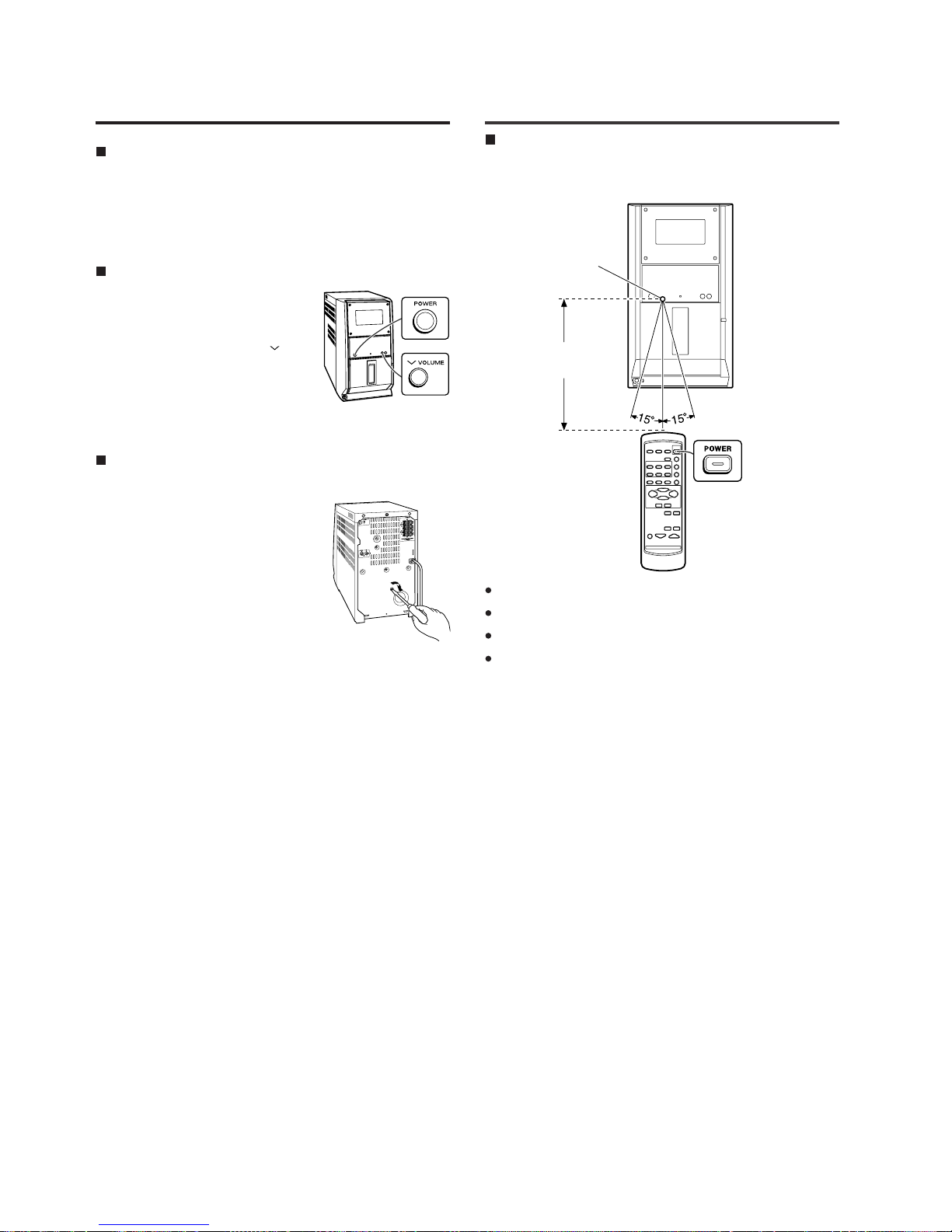
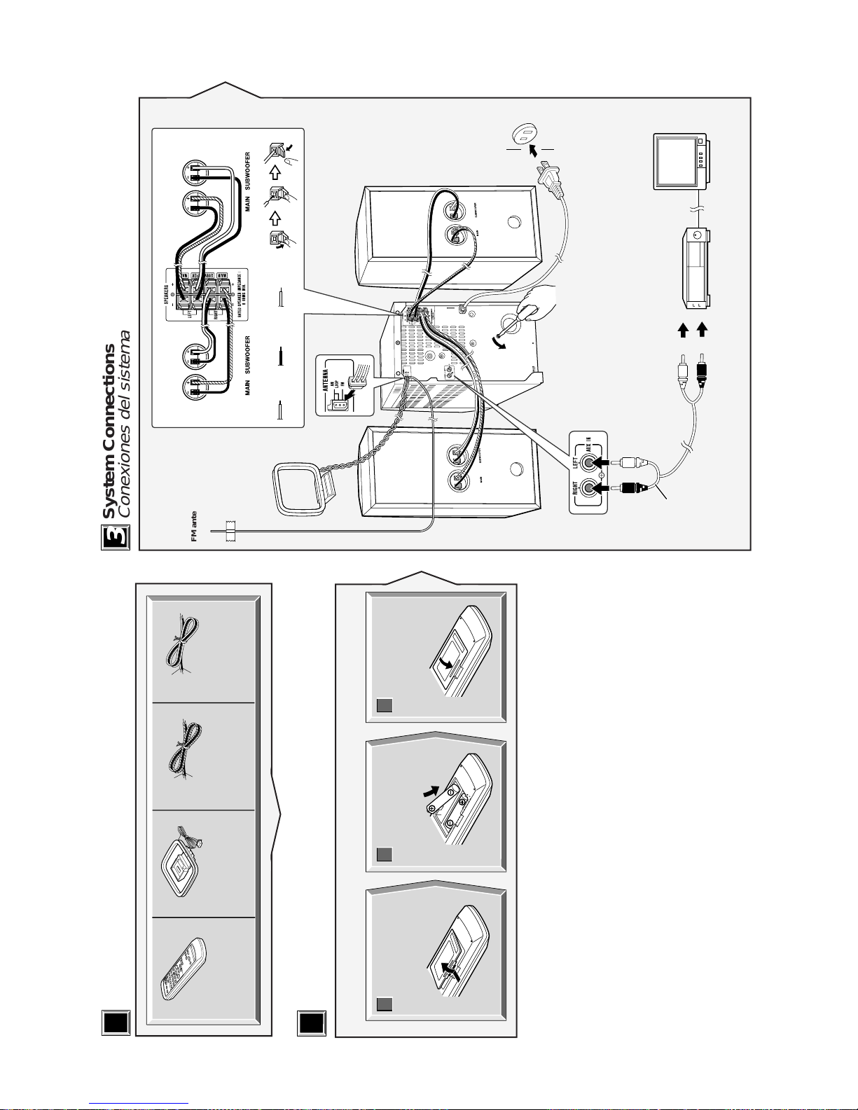
Remote control
Symptom
The remote control does not op-
erate.
Possible cause
Is the unit placed near the TV or com-
puter?
Isthe FM/AMloop antenna placedprop-
erly?
Move the AC power cord away from the
antenna if located near.
Possible cause
Isthe ACpower cordof theunit plugged
in?
Is the battery polarity correct?
Are the batteries dead?
Is the distance or angle incorrect?
Does the remote control sensor receive
strong light?
General
Symptom
The clock is not on time.
Whena buttonis pressed,the unit
does not respond.
No sound is heard.
Possible cause
Did a power failure occur?
Reset the clock.
Set this unit to the power stand-by
mode and then turn it back on.
If the unit still malfunctions, reset it.
Is the volume level set to “0”?
Are the headphones connected?
Are the speaker wires disconnected?
Cassette deck
Symptom
Cannot record.
Cannot record tracks with proper
sound quality.
Cannot erase completely.
Sound skipping.
Cannot hear treble.
Sound fluctuation.
Cannot remove the tape.
Possible cause
Is the erase-protection tab removed?
Is it a normal tape?
(You cannot record on a metal or CrO2
tape.)
Isthere any slack?Isthe tapestretched?
Are the capstan, pinch rollers, or heads
dirty?
Ifa power failureoccursduring playback,
theheads remain engagedwiththe tape.
Do not open the compartment forcibly.
Wait until electricity resumes.
CD player
Symptom
Playback does not start.
Playback stops in the middle or is
not performed properly.
Playback sounds are skipped, or
stopped in the middle of a track.
Possible cause
Is the disc loaded upside-down?
Does the disc satisfy the standards?
Is the disc distorted or scratched?
Istheunitlocated near excessivevibrations?
Is the disc very dirty
?
Has condensation formed inside the
unit?
Condensation
Sudden temperature changes, storage or op-
erationin anextremely humidenvironment may
cause condensation inside the cabinet (CD
pickup, tape heads, etc.) or on the transmitter
on the remote control.
Condensationcan causetheunit tomalfunction.
If this happens, leave the power on with no disc
(or cassette) in the unit until normal playback is
possible (about 1 hour). Wipe off any conden-
sation on the transmitter with a soft cloth before
operating the unit.