Sharp UX-470 User manual

1 - 1
UX-470ES/SE/AT
FO-880ES/AT
Illustration: UX-470
No. 00ZUX470ESSME
CHAPTER 1. GENERAL DESCRIPTION
[1] Specifications ............................................ 1-1
[2] Operation panel......................................... 1-2
[3] Refer to the service manual of UX-370ES.
[4] Refer to the service manual of UX-370ES.
[5] Quick reference guide ............................... 1-9
[6] Refer to the service manual of UX-370ES.
CHAPTER 2. ADJUSTMENTS
[1] Adjustments .............................................. 2-1
[2] Diagnostics and service soft switch .......... 2-2
[3] Troubleshooting ...................................... 2-17
[4] Error code table....................................... 2-18
CHAPTER 3. MECHANISM BLOCKS
[1] Refer to the service manual of UX-370ES.
[2] Refer to the service manual of UX-370ES.
CHAPTER 4. DIAGRAMS
[1] Block diagram ............................................4-1
[2] Wiring diagram .......................................... 4-2
[3] Point-to-point diagram ............................... 4-3
CHAPTER 5. CIRCUIT DESCRIPTION
[1] Circuit description ..................................... 5-1
[2] Circuit description of control PWB ............ 5-2
[3] Circuit description of TEL/LIU PWB .......... 5-8
[4] Circuit description of
power supply PWB............................5-11
[5] Circuit description of CIS unit...................5-11
CHAPTER 6. CIRCUIT SCHEMATICS AND
PARTS LAYOUT
[1] Control PWB circuit ................................... 6-1
[2] TEL/LIU PWB circuit.................................. 6-9
[3] Power supply PWB circuit ...................... 6-17
[4] Operation panel PWB circuit ................... 6-19
CHAPTER 7. OPERATION FLOWCHART
[1] Refer to the service manual of UX-370ES.
[2] Refer to the service manual of UX-370ES.
CHAPTER 8. OTHERS
[1] Refer to the service manual of UX-370ES.
[2] Refer to the service manual of UX-370ES.
PARTS GUIDE
CONTENTS
FACSIMILE
UX-470
MODEL FO-880
Parts marked with " " is important for maintaining the safety of the set. Be sure to replace these parts with specified ones for
maintaining the safety and performance of the set.
This document has been published to be used
for after sales service only.
The contents are subject to change without notice.
SHARP CORPORATION
SERVICE MANUAL
Thisservicemanualis omitted because it is partlycommontoUX-370ES/SE/F/FO-780AT/ES of the servicemanual
of the previous issue. Those common parts are to refer to the service manual of UX-370ES/SE/F/FO-780AT/ES
(00ZUX370ESSME).
SELECTION CODE COUNTRY
UX-470ES/FO-880ES Spain
UX-470SE Sweden
UX-470AT/FO-880AT Austria

1 –2
UX-470ES/SE/AT
FO-880ES/AT
(Danish) ADVARSEL !
Lithiumbatteri-Eksplosionsfare ved fejlagtig håndtering.
Udskiftning må kun ske med batteri af samme fabrikat og type.
Levér det brugte batteri tilbage til leverandoren.
(English) Caution !
Danger of explosion if battery is incorrectly replaced.
Replace only with the same or equivalent type
recommended by the equipment manufacturer.
Discard used batteries according to manufacturer’s
instructions.
(Finnish) VAROITUS
Paristo voi räjähtää, jos se on virheellisesti asennettu.
Vaihda paristo ainoastaan laitevalmistajan suosittelemaan
tyyppiin. Hävitä käytetty paristo valmistajan ohjeiden
mukaisesti.
(French) ATTENTION
Il y a danger d’explosion s’ il y a remplacement incorrect
de la batterie. Remplacer uniquement avec une batterie du
même type ou d’un type recommandé par le constructeur.
Mettre au rébut les batteries usagées conformément aux
instructions du fabricant.
(Swedish) VARNING
Explosionsfare vid felaktigt batteribyte.
Använd samma batterityp eller en ekvivalent
typ som rekommenderas av apparattillverkaren.
Kassera använt batteri enligt fabrikantens
instruktion.
(German) Achtung
Explosionsgefahr beiVerwendung inkorrekter Batterien.
Als Ersatzbatterien dürfen nur Batterien vom gleichen Typ oder
vom Hersteller empfohlene Batterien verwendet werden.
Entsorgung der gebrauchten Batterien nur nach den vom
Hersteller angegebenen Anweisungen.
CAUTION FOR BATTERY REPLACEMENT

1 – 1
UX-470ES/SE/AT
FO-880ES/AT
CHAPTER 1. GENERAL DESCRIPTION
[1] Specifications
Automatic dialing: Rapid Key Dialing: 5 numbers
(UX-470) Speed Dialing: 40 numbers
Automatic dialing: Rapid Key Dialing: 8 numbers
(FO-880) Speed Dialing: 80 numbers
Imaging film: Initial starter roll (included with fax
machine): 10 m roll (approx. 30 A4
pages)
Replacement roll:
UX-3CR/FO-3CR 30 m roll (two rolls in
package, one roll yields approx. 95 A4
pages)
Automatic document feeder: 10 sheets max.
Memory size*: 512 KB (approx.30 average pages with
no voice messages recorded, or 24
minutes of voice messages (including
OGMs) with no documents in memory)
Modem speed: 9600 bps with automatic fallback to
7200, 4800, or 2400 bps
Transmission time* : Approx. 15 seconds (Sharp special mode)
Display: 7 ×5 dots, 1 line by 16-digit display
Reception modes: FAX, TEL, TEL/FAX, A.M.
Resolution: Horizontal:
8 dots/mm
Vertical:
Standard: 3.85 lines/mm
Fine/Halftone: 7.7 lines/mm
Super fine: 15.4 lines/mm
Recording system: Thermal transfer recording
Halftone (grayscale): 64 levels
Applicable telephone line: Public switched telephone network / PBX
Compatibility: ITU-T (CCITT) G3 mode
Configuration: Half-duplex, desktop transceiver
Compression scheme: MH, MR, Sharp
Scanning method: Sheet-feeder CIS (Contact Image Sensor)
Effective recording width: 204 mm max.
Input document size: Automatic feeding:
Width 148 to 210 mm
Length 140 to 297 mm
Manual feeding:
Width 148 to 210 mm
Length 140 to 600 mm
Effective scanning width: 210 mm max.
Contrast control: Automatic/Dark selectable
Copy function: Single/Multi-copy/Sort-copy(99 copies/
page)
Telephone function: Standard
(cannot be used for incoming/outgoing
if power fails)
Noise emission: Less than 70 dBA (Measured
according to DIN 45635.)
Power requirements: 220-230 V AC, 50 Hz
Operating temperature: 5 to 35°C
Humidity: Maximum: 85 %
Power consumption: Stand-by: 3.0 W
Maximum: 115 W
Dimensions: Width: 343 mm
Depth: 313 mm
Height: 312 mm
Weight: Approx. 3.4 kg
* BasedonITU-T(CCITT)TestChart#1atstandardresolutioninSharp
special mode, excluding time for protocol signals (i.e., ITU-T phase C
time only).
Note: The facsimile machine is Year 2000 compliant.
As a part of our policy of continuous improvement, SHARP reserves the right to make design and specification changes for procduct
improvement without prior notice.The performance specifications figures indicated are nominal values of production units.There may be some
deviation from these values in individual units.

1 – 2
UX-470ES/SE/AT
FO-880ES/AT
[2] Operation panel
JKL
SPEED
DIAL
REDIAL
SPEAKER
SEARCH
REPEAT REC/MEMO
PLAY/SKIP
DELETE
STOP
COPIA/AIUTO
START/MEMORY
VOLUME
DOWN UP
RECEPTION
MODE
RESOLUTION FUNCTION
FAX
A.M.
TEL
ABC
2
1
DEF
3
WXYZ
9
GHI
45
MNO
6
PQRS
7
TUV
8
0
05/POLL04030201
TEL/FAX
R
SYMBOLS
DIGITAL
ANSWERING
SYSTEM
13 15 1718
12
10
11
1 6 7 8
2 3
19
9
45
14 16
08/POLL07060504
030201
(FO-880)
(UX-470)
1. SPEED DIAL key (KURZWAHL)
(Tecla MARCACION RAPIDA)
Press this key to dial a 2-digit Speed Dial number.
2. REDIAL key (WAHLWDH.) (Tecla RELLAMADA)
Press this key to automatically redial the last number dialed.
3. REPEAT key (ZURÜCK) (Tecla RETROCESO)
Press this key to repeat playback of a message.
4. Display (LCD-Anzeige) (Display de cristal líquido)
This displays messages and prompts during operation and
programming.
5. PLAY/SKIP key (WIEDERG/VOR.)
(Tecla FUNCIONAR/OMITIR)
Press this key to play recorded messages. During playback,
press it to skip forward to the next message.
6. RECEPTION MODE key (EMPFANGSART)
(Tecla MODO DE RECEPCION)
Press this key to select the reception mode. An arrow in the
display will point to the currently selected reception mode.
7. RESOLUTION key (AUFLÖSUNG)
(Tecla RESOLUCION)
Press this key to adjust the resolution and contrast before
sending or copying a document.
8. VOLUME keys (LAUTSTÄRKE) (Teclas VOLUMEN)
Press these keys to adjust the volume of the speaker when the
SPEAKER key has been pressed, or the volume of the ringer
at all other times.
9. FUNCTION key (FUNKTION) (Tecla FUNCION)
Press this key to select various special function.
10. Panel release (BEDIENFELD ENTRIEGELN)
(Liberación del panel)
Grasp this finger hold and pull toward you to open the operation
panel.
11. Number keys (Zifferntasten) (Teclas numéricas)
Use these keys to dial numbers, and enter numbers and
letters during number/name storing procedures.
12. SEARCH/R key (ALPHAWAL/R)
(Tecla BUSQUEDA/R)
Press this key to search for an automatic dialing number,
or, if you are on a P.B.X. extension, press this key t
o
transfer.
13. SPEAKER key (LAUTSPR.) (Tecla ALTAVOZ)
Press this key to hear the line and fax tones through the
speaker before sending a document, or dialing a voice
number.
Note: This is not a speakerphone. You must pick up the
handset to talk with the other party.
14. REC/MEMO key (AUFN.)
(Tecla GRABACION/MEMORIA)
Press this key to record a phone conversation or a
message.
15. Rapid Dial keys (Zielwahltasten) (Teclas rápidas)
Press one of these keys to dial a fax or voice number
automatically. (Note that you must attach the Rapid Key
labels.)
16. DELETE key (LÖSCHEN) (Tecla BORRAR)
Press this key to erase recorded message.
17. STOP key (STOP) (Tecla STOP)
Press this key to cancel operations before they are
completed.
18. START/MEMORY key (START/SPEICHER)
(Tecla INICIO/MEMORIA)
Press this key to send or receive a document, or to scan a
document into memory before sending it.
19. COPY/HELP key (KOPIE/HILFE)
(Tecla COPIA/AYUDA)
When a document is in the feeder, press this key to make
a copy. At any other time, press this key to print out the
Help List, a quick reference guide to the opeation of your
fax.

1 – 3
UX-470ES/SE/AT
FO-880ES/AT
Normal Dialing
1. Lift the handset or press
2. Dial the fax number.
3. Wait for the reception tone (if a person answers, ask them to press their Start
key).
4. Press:
Rapid Key Dialing
Press the appropriate Rapid Key.Transmission will begin automatically.
Speed Dialing
1. Press:
2. Enter 2-digit Speed Dial number.
3. Press:
RECEIVING DOCUMENTS
Press:
FAX mode:The fax automatically answers 1 or 2 rings and receives the incoming
document.
TEL mode:
TEL/FAX mode: The fax machine automatically answers on 1 or 2 rings and re-
ceives faxes. Voice calls (including manually dialled fax transmissions) are sig-
nalled by a special ringing sound.
A.M. mode:Select this mode when you go out to receive both voice messages and
faxes.
SETTINGTHE DATE ANDTIME
Note: Imaging film and paper must be loaded to perform the following operation.
Press:
Display shows: DATE & TIME SET
Press the START/MEMORY key:
Enter two digits for the Day (01 through 31).
Enter two digits for the Month (01 through 12).
Enter four digits for the Year (Ex: 1999).
Enter two digits for the Hour (01 through 23).
Enter two digits for the Minute (00 through 59).
When finished, press:
STORING AND CLEARING NUMBERS FOR AUTOMATIC DIALING
Note: Imaging film and paper must be loaded to perform the following operation.
1. Press:
Display shows: FAX/TEL # MODE
2. Press 1to store a number or 2to clear a number.
3. Enter a 2-digit Speed Dial number (from 01 to 05 for Rapid Key Dialing, or 06
to 45 for Speed Dialing) (FO-880 from 01 to 08 for Rapid Key Dialing, or 09 to
88 for Speed Dialing). (If you are clearing a number, go to Step 7.)
4. Enter the full telephone/fax number.
5. Press:
6. Enter the name of the location by pressing number keys (max. of 20 charac-
ters).(Refer tothe letterentrytablein ENTERINGYOUR NAMEAND NUMBER.)
7. Press:
SENDING DOCUMENTS
TEL.
SET TEL.
LINE
1
2
3
A =
B =
C =
D =
E =
F =
G =
H =
I =
J =
K =
L =
M =
N =
O =
P =
Q =
R =
S =
T =
U =
V =
W =
X =
Y =
Z =
SPACE =
SPEED DIAL
REDIAL
SEARCH
SPEAKER
ABC DEF
JKL MNO
GHI
TUV WXYZ
PQRS
SYMBOLS
R
Deletes high-
lighted letter
Upper/lower
case shift key
Moves cursor
to the left
Moves cursor
to the right
Press either key one or more times to select
and enter a symbol.
START/MEMORY
STOP
FUNCTION (ES/SE)
3
FUNCTION (AT)
3
,
SPEAKER
FUNCTION
3
SPEED DIAL
FAX
TEL
A.M.
FAX
TEL
A.M.
14 FEB 10:30
14 FEB 10:30
TEL/FAX
TEL/FAX
FAX
TEL
A.M.
14 FEB 10:30
TEL/FAX
FAX
TEL
A.M.
14 FEB 10:30
TEL/FAX
RECEPTION
MODE
Fax
tone
RECEIVING
START/MEMORY
6. Press:
ENTERINGYOUR NAME AND NUMBER
Note: Imaging film and paper must be loaded to perform the following operation.
1. Press:
FUNCTION
3
Display shows: OWN NUMBER SET
2. Press:
3. Enter your fax number (max. of 20 digits) by pressing the number keys.
♦If you make a mistake, press the SEARCH/R key to move the cursor
back to the mistake, then enter the correct number or letter.
4. Press:
5. Enter your name by pressing the appropriate number keys as shown below.
♦Toenter twoletters insuccession that requirethe samekey, pressthe SPEAKER
key after entering the first letter.
6. When finished, press:
[5] Quick reference guide
INSTALLATION
1. Connect the handset as shown.
2. Plug the power cord into an earthed, 220-230 V outlet.
3. Plug one end of the telephone line into the TEL.LINE socket on the rear of the
fax, and the other end into your telephone wall socket.
RECORING AN OUTGOING MESSAGE
1. Press:
Display shows: OGM RECORDING
2. Press:
3. Press 1(GENERAL) to record an outgoing message for the answering ma-
chine. Press 2 (TRANSFER) to record an outgoing message for the Transfer
function.
4. Pickupthe handset, pressthe START/MEMORY key,andspeak into the hand-
set to record your message.
5. When finished, press the STOP key or replace the handset.
Place your document (up to 10 pages)
face down in the document feeder.
1 – 9
FUNCTION
0
START/MEMORY
STOP
STOP
START/MEMORY
START/MEMORY
START/MEMORY
START/MEMORY
STOP
START/MEMORY
START/MEMORY
STOP
START/MEMORY
START/MEMORY

1 – 4
UX-470ES/SE/AT
FO-880ES/AT
M E M O
1 – 11

UX-470ES/SE/AT
FO-880ES/AT
CHAPTER 2. ADJUSTMENTS
[1] Adjustments
General
Sincethefollowingadjustments and settings are providedforthismodel,
make adjustments and/or setup as necessary.
1. Adjustments
Adjustments of output voltage (FACTORY ONLY)
1. Install the power supply unit in the machine.
2. Set the recording paper and document.
3. When the document is loaded, power is supplied to the output lines.
Confirm that outputs are within the limits below.
Output voltage settings (1)FU100 (ICP-S07) is installed in order to protect IC’s from an over-
current generated in the motor drive circuit.If FU100 is open, replace
it with a new one.
3. Settings
(1) Dial mode selector
(UX-470ES/AT/FO-880ES/AT)
DIAL mode (Soft Switch No. SWB4 DATA No. 3)
Output Voltage limits
+5V 4.75V ∼ 5.25V
+24V 23.3V ∼ 24.7V 1MG
2MG
3 +24V
4 +24V
5 +24V
6DG
7 +5V
8DG
9 PSAVE
Connector
No. CNPW
Pin No.
2 – 1
TEL/LIU PWB
POWER
SUPPLY
PWB
CONTROL
PWB
CNLIUA
CNLIUA CN1
CNPW
CNTH
CNPN
CNCIS
CNSP
CNMT
CNCSW
CNLIUB
CNLIUB
2. IC protectors replacement
ICPs (IC Protectors) are installed to protect the motor driver circuit.
ICPsprotectvarious ICs and electronic circuits from an overcurrent con-
dition.
The location of ICPs are shown below:
CONTROL PWB
(BOTTOM SIDE)
CNPW CNLIUA
FU100
CNLIUB
(step 1) Select "OPTION SETTING".
KEY : FUNCTION 4
DISPLAY: OPTION SETTING PRESS OR #
(step 2) Select "DIAL MODE".
KEY: Push # until " DIAL MODE " is
indicated because the number of
# s changes by the model.
DISPLAY: DIAL MODE
(step 3) Select, using "1" or "2".
KEY: 1
DISPLAY: TONE SELECTED
KEY: 2
DISPLAY: PLUSE SELECTED
(step 4) End, using the "STOP" key.
KEY:
Cursor
When initially registering,
the mode shows 1=TONE.
When registering again, the
mode which was registered
formerly is shown.
STOP
1=TONE, 2=PULSE
(UX-470SE)
Setting is not required since the required mode is TONE ONLY.

UX-470ES/SE/AT
FO-880ES/AT
[2] Diagnostics and service soft switch
1. Operating procedure
(1) Entering the diagnostic mode
Press FUNC →9 →→ 8 →# →7 , and the following display will appear.
ROM Ver. FLN0 (FMM0 , FMH0 , FLP0 , FMI0 ) After 2 sec: DIAG MODE
FLN0 (UX-470ES)
FMM0 (UX-470SE)
FMH0 (UX-470AT)
FLP0 (FO-880ES)
FMI0 (FO-880AT)
Then press the START key. Select the desired item with the key or the # key or select with the rapid key. Enter the mode with the START key.
(Diag•specifications)
If the diag mode cannot be set, repeat the diag mode operation, per-
forming the following operation.
After the power is turned on and "WAIT A MOMENT" is indicated, press
the STOP key.
2 – 2
In relation with the process response (request from Production
Engineering) "WAIT A MOMENT"clockindication mayappeardepending
onSTOP keytiming.If the STOPkey is helddown, "MEMORY CLEAR?"
appears.
FUNC DIAG MODE
9 8 7
START 1Soft switch mode
START 2ROM & RAM check
START 3Aging mode
START 4Panel key test
START 5Check pattern
START 6Signal send mode
Auto feeder mode
START
START
Message print
START
—Ring & Dial free
START
—
Flash memory check
Flash memory clear
START
START—
START
KEY
STOP
KEY
+
"Power ON"
Memory clear
(Work + Backup)
FLN0
All black mode
START
—
FMH0
START 7Memory clear Shading mode
START
8
—
—
FMM0
FLP0
FMI0
2. Diagnostic items
ITEM DIRECT DIRECT
No. key key Contents Function
(UX-470)
(FO-880)
1 1 1 SOFT SWITCH MODE Soft switches are displayed and changed. List can be output.
2 2 2 ROM & RAM CHECK ROM is sum-checked, and RAM is matched. Result list is output.
3 3 3 AGING MODE 10 sheets of check patterns are output every 5 minutes per sheet.
4 4 4 PANEL KEY TEST Panel keys are tested. Result list is output.
5 5 5 CHECK PATTERN Check pattern is output.
6 — 6 SIGNAL SEND MODE Various signals of FAX communication are output.
7 — 7 MEMORY CLEAR Back-up memory is cleared, and is set at delivery.
8 — 8 SHADING MODE Shading compensation is performed in this mode.
9 — — ALL BLACK PRINT To check the print head, whole dots are printed over the interval of 2 m.
10 — — AUTO FEEDER MODE Insertion and discharge of document are tested.
11 — — MESSAGE PRINT
The display message of each language is printed out together with the English equivalent.
12 — — RING & DIAL FREE Allows CI detection of 13Hz or more. Eliminates dial tone detection in auto dial.
13 — —
FLASH MEMORY CHECK
Checks flash memory write/read.
14 — —
FLASH MEMORY CLEAR
Checks flash memory clearing.

UX-470ES/SE/AT
FO-880ES/AT
3. Diagnostic items description
3. 1. Soft switch mode
Used to change the soft switch settings.
The soft switch which is stored internally is set by using the keys.
The available soft switches are SW-A1 to SW-M2.
The content of soft switches is shown in page 2-5 to 2-16.
The contents are set to factory default settings.
3. 2. ROM & RAM check
ROM executes the sum check, and RAM executes the matching test.
The result will be notified with the number of short sounds of the buzzer
as well as by printing the ROM & RAM check list.
Number of short sounds of buzzer 0 →No error
1 → ROM error
2 → RAM error (32Kbyte)
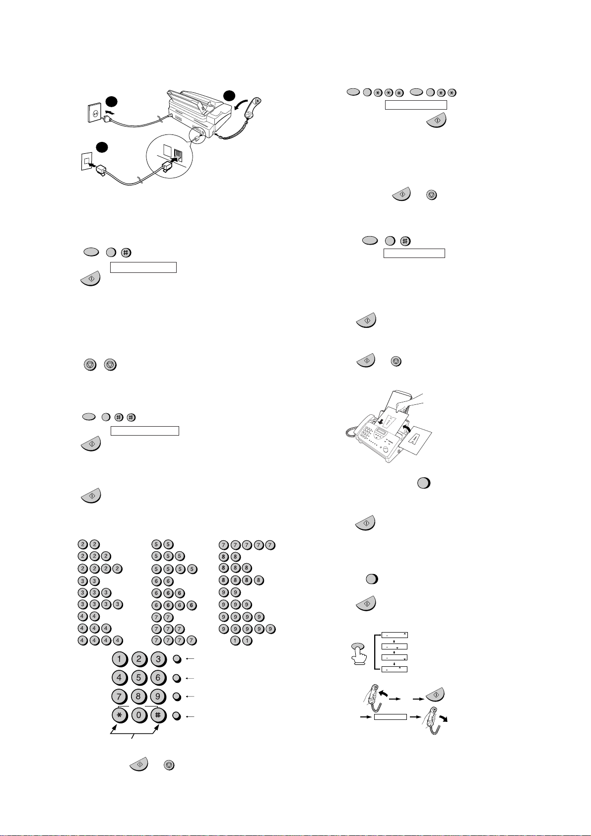
3. 3. Aging mode
Ifany document is first present, copyingwill be executed sheet by sheet.
If no document is present, the check pattern will be printed sheet by
sheet.This operation will be executed at a rate of one sheet per 5min-
utes, and will be ended at a total of 10 sheets.
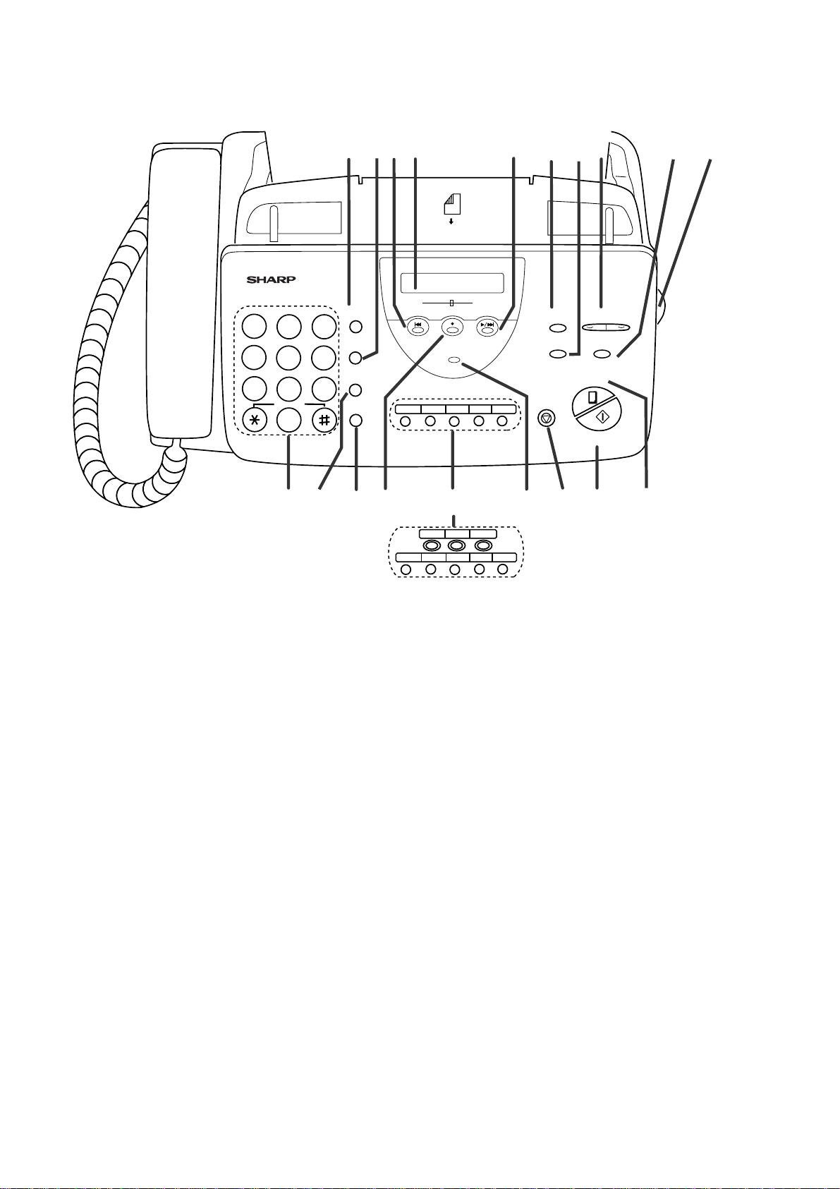
3. 4. Panel key test
This mode is used to check whether each key operates properly or not.
Press the key on the operation panel, and the key will be displayed on
the display.Therefore, press all keys.At this time,finally press the STOP
key.
When the STOP key is pressed, the keys which are not judged as
"pressed" will be printed on the result list.
• LED port of the contact image sensor (CIS) is kept on during the term
from when start of the panel test mode to end with the STOP key.
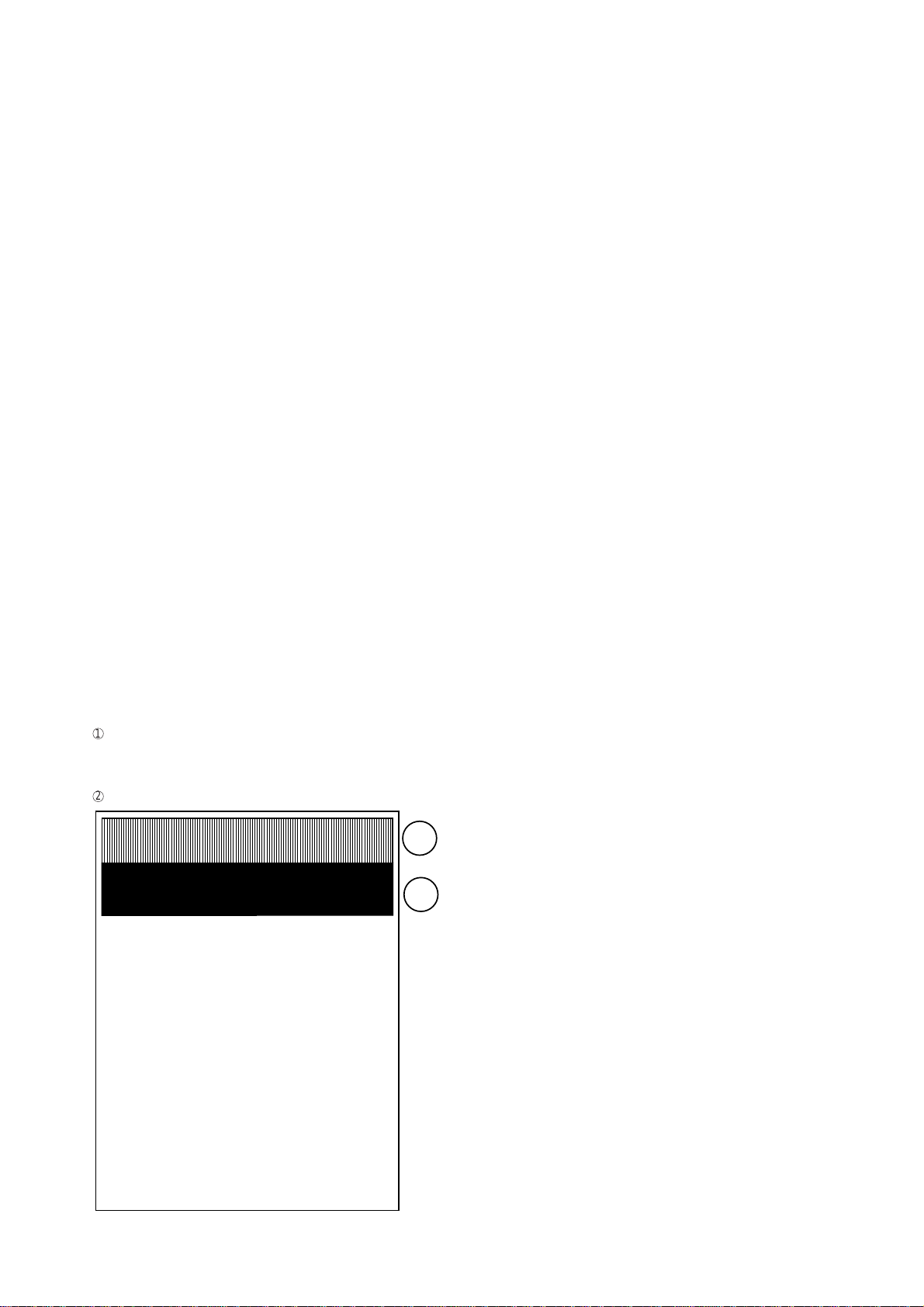
3. 5. Check pattern
This mode is used to check the state of the printing head. It is ended
with the following pattern printed on one printing sheet.
1
Longitudinal stripe 2 Approx.30 mm
2 black dots and 2 white dots are repeatedly progressed on one
line.
2
Full black Approx. 30 mm
3. 6. Signal send mode
This mode is used to send various signals to the circuit during FAX com-
munication. Every push of START key sends a signal in the following
sequence.Moreover, the signal soundis also output to the speakerwhen
the line monitor of the soft switch is on.
[1] No signal (CML signal turned on)
[2] 9600bps
[3] 7200bps
[4] 4800bps
[5] 2400bps
[6] 300bps (FLAG)
[7] 2100Hz (CED)
[8] 1100Hz (CNG)
[9] END
3. 7. Memory clear
This mode is used to clear the backup memory and reset to the default
settings.
3. 8. Shading mode
The mode is used for the shooting compensation. For reading, set up
the special original paper.
The shooting compensation memorizes the reference data of white and
black for reading.
Moreover, the memorized data is not erased even if memory clear mode
is executed.
3. 9. All black print
This mode is used to check the state of the printing head and inten-
tionally overheat it. Whole dots are printed over the interval of 2 m. If it is
overheated or the printing sheet is jammed, press STOP key for the end.
3. 10. Auto feeder mode
In this mode, a document is inserted and discharged to check the auto
feed function.
After this mode is started, set a document, and the document feed will
be automatically tested.
3. 11. Message print
Usedtoprintthedisplayedmessage of communication for translate each
language.
3. 12. Ring & Dial free
Used to reject dial tone check while autodialing is carried out.And used
to change the bottom Ring frequency of auto-receiving to 13Hz.
3. 13. Flash memory check
Data is written into and read from the flash memory to check the data
conformity.When the unit enters this mode, the check is started.
3. 14. Flash memory clear
Data in the flash memory is cleared (memory clear).When the unit en-
ters this mode, the check is started.
The result is announced by the buzzer beeps. The result of check is
printed.
Beeps
0 → No error
1 → Memory error
2 – 3
1
2

UX-470ES/SE/AT
FO-880ES/AT
4. How to make soft switch setting
Toenterthesoftswitchmode,makethe following keyentries in sequence.
2 – 4
Press FUNCTION 9 8 7 STARTSTART
Press FUNCTION key.
Press key.
Press key.
Bit1 - 8 are set.
Soft SW-A2 - SW-M2 are set.
S F T SW-A1 = 1 0 0 0 0 0 0 0
S F T SW-A2 = 0 0 0 0 0 0 0 0
S F T SW-M2 = 0 0 0 0 0 0 0 0
Press key during setting.
To finish the settings halfway between
SW-A1 and SW-M2, press the STOP
key. In this case, the setting being done
to the SW No. on display will be nullified
while settings done to the preceding
SW Nos. remain in effect.
The soft switch mode is terminated.
S F T SW-A1 = 0 0 0 0 0 0 0 0
START
DATA No. 1 2 3 4 5 6 7 8
When the COPY key is pressed, the
contents of soft switches are printed.

UX-470ES/SE/AT
FO-880ES/AT
2 – 5
1 Protect from echo No Yes 0 0 0
2 Forced 4800 BPS reception Yes No 0 0 0
3 Footer print Yes No 0 0 0
4 Length limitation of No limit Copy/send:60cm 0 0 0
copy/send/receive Receive: 1m
5 CSI transmission No transmitted Transmitted 0 0 0
6
DIS receive acknowledgement
Twice NSF: Once 0 0 0
during
G3 transmission DIS:Twice
7 Non-modulated carrier for V29 Yes No 0 0 0
transmission modem
8 EOL detect timer 25 s 13 s (ES : 5s) 0 0 0
Modem speed V.29 V.27 ter
9600 7200 4800 2400
1 No.10000000
2 No.20000000
3 No.30110000
4 No.41100111
5 Sender’s information transmit No Yes 0 0 0
6 H2 mode No Yes 0 0 0
7 Communication error treatment in No communication Communication error 0 0 0
RTN sending mode (reception) error
8 CNG transmission No Yes 0 0 0
CED tone signal interval 1000ms 750ms 500ms 75ms
1 No.11100000
2 No.21010000
3 MR coding No Yes 0 0 0
4 Reserved 000
5 Reserved 000
6 Reserved 000
7 Reserved 000
8 Reserved 000
1 Signal transmission level Binary input 0 0 0
2No.=168421111
312345011
4 0 1 0 1 1 (ES) 1 0 0
5 0 1 1 0 0 (SE/AT) 1 0 0
6 Protocol monitor (error print) Printed at com. error Not printed 0 0 0
7 Protocol monitor Yes No 0 0 0
8 Line monitor Yes No 0 0 0
Digital line equalization setting 7.2km 0km
1 (Reception) No. 1 1 0 1 1 1
2No.210111
3 Reserved 000
4 Reserved 000
Digital cable equalizer setting 7.2km 0km
5 (Reception for Caller ID) No. 5 1 0 0 0 0
6 (SE only) No. 6 1 0 0 0 0
7 Error criterion 10 ~ 20 % 5 ~ 10 % 0 0 0
8 Anti junk fax check Yes No 0 0 0 OPTION
5. Soft switch description
•Soft switch
SW
NO. DATA
NO. ITEM Switch setting and function
10Remarks
Initial setting
SW
l
A1
SW
l
A2
SW
l
A3
SW
l
A5
SW
l
A4
ES SE AT

UX-470ES/SE/AT
FO-880ES/AT
2 – 6
1 Auto gain control (MODEM) Enable Disable 1 1 1
2 End Buzzer Yes No 1 1 1
3 Disconnect the line when DIS is No Yes 1 1 1
received in RX mode
4 Equalizer freeze control (MODEM) On Off 0 0 0
5 Equalizer freeze control 7200 BPS No Yes 0 0 0
only
6 CNG transmission in manual TX Yes No 1 1 1
mode
7 Initial compression scheme for sharp MR mode H2 mode 0 0 0
fax in TX mode
8 Reserved 000
1 Reserved 000
2 Reserved 000
3 Reserved 000
4 Reserved 000
5 Recall times Binary input 0 0 0
6 No.= 8421 0 0 0
7 5678 1 1 1
8 0010 0 0 0
1 Dial pausing (sec/pause) 4 sec 2 sec 1 1 1
2 Dial tone detection (before auto dial) No Yes 0 0 0
3 Reserved 000
4 Busy tone detection (after auto dial) No Yes 0 0 0
5 Waiting time after dialing 90 sec 45 sec 0 0 0
6 Reserved 000
7 Reserved 000
8 PBX connection Yes No 0 0 0 OPTION
PBX recall function (R key select) No. Earth Flash OPTION
1No.1011111
2No.2001111
3 Reserved 000
PBX select ID Earth Flash OPTION
4No.4011000
5No.5001000
6 Reserved 000
7 Reserved 000
8 Reserved 000
1 Reserved 000
2 Reserved 000
3 Dial mode Tone Pulse 0 1 1 OPTION
(ES/AT only)
4 Pulse →Tone change function Enable Disable 1 1 1
by key
5 Reserved 000
6 Reserved 000
7 Reserved 000
8 Reserved 000
SW
NO. DATA
NO. ITEM Switch setting and function
10Remarks
Initial setting
SW
l
A6
SW
l
B1
SW
l
B2
SW
l
B4
SW
l
B3
ES SE AT

UX-470ES/SE/AT
FO-880ES/AT
2 – 7
1 DTMF signal transmission level Binary input 0 1 0
2 (Low) No. = 16 8 4 2 1 1 0 1
312345111
4 0 1 1 1 0 (ES/AT) 1 0 1
5 1 0 1 0 0 (SE) 0 0 0
6 Reserved 000
7 Reserved 000
8 Reserved 000
1 DTMF signal transmission level Binary input 0 1 0
2 (High) No. = 16 8 4 2 1 1 0 1
312345000
4 0 1 0 1 1 (ES/AT) 1 0 1
5 1 0 0 0 1 (SE) 1 1 1
6 Reserved 000
7 Reserved 000
8 Reserved 000
Reading slice (Binary) Factory Light Dark
Darker in
setting
dark mode
1 No.10101000
2 No.20011000
Reading slice (Half tone) Factory Light Dark
Darker in
setting
dark mode
3 No.30101000
4 No.40011000
5 Line density selection Fine Standard 0 0 0 OPTION
6 Halftone gray scale selection 16 level 64 level 0 0 0 OPTION
7 MTF correction in half tone mode No Yes 0 0 0
8 Reserved 000
Number of rings for auto receive Binary input OPTION
1No.=8421000
21234000
3 0 0 1 0 (ES) 1 0 0
4 0 0 0 1 (SE/AT) 0 1 1
5 Automatic switching manual to auto Reception after 5 No reception 0 0 0
receive mode rings
6 Reserved 000
7 CI detection 13 Hz or more As is PTT 0 0 0
8 Reserved 000
1 Reserved 000
2 Reserved 000
3 Reserved 000
4 Reserved 000
5 Caller ID function (SE only) Yes No 0 0 0 OPTION
(SE only)
6 Reserved 000
7 Reserved 000
8
Caller ID detect during CI off (SE only)
All times Only first 0 0 0
1 Tel/Fax Automatic switching mode Tel/Fax auto switch Switch to Fax 1 1 1
Pseudo ringing time at phone/fax 15sec 60sec 30sec 120sec OPTION
2 automatic switching mode No. 2 0 0 1 1 0 0 0
3 No.30101000
4
Number of CNG signal detection at the
Twice Once 1 1 1
tel/fax automatic switching mode
5 Reserved 000
6 Reserved 000
7 Post answer tone (transmit in No Yes 0 0 0
Tel/Fax mode)
8 Reserved 000
SW
NO. DATA
NO. ITEM Switch setting and function
10Remarks
Initial setting
SW
l
B5
SW
l
B6
SW
l
C1
ES SE AT
SW
l
D2
SW
l
D1
SW
l
E1

UX-470ES/SE/AT
FO-880ES/AT
2 – 8
1 Pseudo ringer sound volume Binary input 0 0 0
2 No.= 8421 1 1 1
3 1234 0 0 0
4 0101 1 1 1
5 Reserved 000
6 Reserved 000
7 Reserved 000
8 Reserved 000
DTMF detection time 50ms 80ms 100ms 120ms
1No.10011000
2No.20101000
3 Protection of remote reception Yes No 0 0 0 OPTION
(5 ) detect
4 Remote reception with GE Compatible Not compatible 1 1 1
telephone
5 Remote operation code figures by Binary input 0 0 0 OPTION
6 external TEL (0~9) No. = 8 4 2 1 1 1 1
7 5678 0 0 0
8 0101 1 1 1
1 CNG detection in STAND-BY mode Yes No 1 1 1 OPTION
Number of CNG detect (AM mode) 1pulse 2pulses 3pulses 4pulses
2No.20011000
3No.30101111
Number of CNG (STAND-BY mode) 1pulse 2pulses 3pulses 4pulses
4No.40011000
5No.50101111
6 Reserved 000
7 Reserved 000
8 Reserved 000
1 Reserved 000
2 Reserved 000
3 Reserved 000
4 Reserved 000
5 Reserved 000
6 Reserved 000
7 Reserved 000
8 Reserved 000
1 Reserved 000
2 Reserved 000
3 Reserved 000
4 Reserved 000
5 Reserved 000
6 Reserved 000
7 Reserved 000
8 Reserved 000
1 Reserved 000
2 Reserved 000
3 Reserved 000
4 Reserved 000
5 Reserved 000
6 Reserved 000
7 Reserved 000
8 Reserved 000
SW
NO. DATA
NO. ITEM Switch setting and function
10Remarks
Initial setting
SW
l
E2
SW
l
F1
SW
l
F2
SW
l
G2
SW
l
G1
SW
l
G3
ES SE AT

UX-470ES/SE/AT
FO-880ES/AT
2 – 9
1 Reserved 000
2 Reserved 000
3 Reserved 000
4 Busy tone continuous sound detect 5 sec As is PTT 1 1 1
time
5 Busy tone detect continuation sound No Yes 1 1 1
detect during OGM
6 Busy tone detect continuation sound No Yes 0 0 0
detect (during ICM : for internal A.M.)
7 Busy tone detect intermittent sound No Yes 1 1 1
during OGM
8 Busy tone detect intermittent sound No Yes 0 0 0
detect (during ICM : for internal A.M.)
Busy tone detection pulse number 2pulses 4pulses 6pulses 10pulses
1 No.10011111
2 No.20101100
3 Fax switching when A.M. full Yes No 0 0 0 OPTION
4 Reserved 000
5 Reserved 000
6 Reserved 000
7 AM OGM announce only mode Yes No 0 0 0 OPTION
8 Reserved 000
ICM recording time 4min 15s 30s 60s OPTION
1 No.10011001
2 No.20101001
A.M. quiet time 1 2s 3s 4s 5s
3 No.30011000
4 No.40101000
A.M. quiet time 2 0s 1s 2s 3s
5 No.50011111
6 No.60101000
7 Key input buzzer on/off switch On Off 0 0 0
(Two way recording mode)
8 Reserved 000
1 A.M. quiet detect time Binary input 0 0 0
2No.=168421000
3 12345111
4 00110111
5000
6 Reserved 000
7 Reserved 000
8 Alarm during two way alarm Yes No 0 0 0
1 Max OGM record time 15s 60s 0 0 0
2 Reserved 000
3 Two way record function Disable Enable 1 0 0
4 Toll saver Disable Enable 0 0 0 OPTION
5 Reserved 000
6 Reserved 000
7 Reserved 000
8 Transfer dial recall No Yes 0 0 0
SW
NO. DATA
NO. ITEM Switch setting and function
10Remarks
Initial setting
SW
l
H1
SW
l
H2
SW
l
I1
SW
l
I3
SW
l
I2
ES SE AT

UX-470ES/SE/AT
FO-880ES/AT
2 – 10
1 AGC maximum gain (line) Binary input 1 1 1
2 (10~25dB)(1dB step) No.= 8 4 2 1 1 1 1
3 1234 0 0 0
4 1100 0 0 0
5 AGC maximum gain (Mic) Binary input 1 1 1
6 (10~25dB)(1dB step) No.= 8 4 2 1 0 0 0
7 5678 1 1 1
8 1010 0 0 0
1 AGC eref access code (line) Binary input 1 1 1
2 (-0~-30dB)(2dB step) No. = 8 4 2 1 0 0 0
3 1234 0 0 0
4 1000 0 0 0
5 AGC eref access code (Mic) Binary input 1 1 1
6 (-0~-30dB)(2dB step) No. = 8 4 2 1 0 0 0
7 5678 0 0 0
8 1000 0 0 0
1 AGC gain adaptation threshold (line) Binary input 1 1 1
2 No.= 8421 1 1 1
3 1234 1 1 1
4 1111 1 1 1
5 AGC gain adaptation threshold (Mic) Binary input 1 1 1
6 No.= 8421 1 1 1
7 5678 1 1 1
8 1111 1 1 1
AGC slew rate (line) Slow Normal
Little fast
Fast
1 No.10011000
2 No.20101111
AGC slew rate (Mic) Slow Normal
Little fast
Fast
3 No.30011000
4 No.40101111
5 Reserved 000
6 Reserved 000
7 Reserved 000
8 Reserved 000
1 Activity report print Automatic printout No printout when 0 0 0 OPTION
memory full
2 Total communication hours and No Yes 0 0 0
pages print
3 Sender’s phone number setting Cannot change Change allowed 0 0 0
4 Reserved 000
5 Reserved 000
6 Summer time setting No Yes 0 0 0
Ringer volume Off Low Middle High OPTION
7No.70011111
8No.80101000
1 Reserved 000
2 Reserved 000
3 Polling key Yes No 0 0 0 OPTION
4 Reserved 000
5 Reserved 000
Speaker volume (5 stages)
Very Low
Low Middle High
Very High
OPTION
6 No.600001000
7 No.700110111
8 No.801010000
SW
NO. DATA
NO. ITEM Switch setting and function
10Remarks
Initial setting
SW
l
I5
SW
l
I6
SW
l
I7
SW
l
J2
SW
l
J1
SW
l
I4
ES SE AT

UX-470ES/SE/AT
FO-880ES/AT
2 – 11
1 Automatic cover sheet Yes No 0 0 0 OPTION
Communication results printout
E/T/M
Send only
Always
No print Err only
OPTION
2 (Transaction report) No. 2 0 0 0 0 1 1 1 1
3No.300110000
4No.401010000
5 Reserved 000
6 Reserved 000
7 Reserved 000
8 Reserved 000
1 Entering DIAG mode by pressing Yes No 0 0 0
SPEED key
2 Reserved 000
3 OGM/ICM output level Binary input 0 0 0
4 No.=32168421 1 1 1
5 345678 0 0 0
6 010001 0 0 0
7000
8 111
1 Reserved 000
2 Reserved 000
3 Reserved 000
4 Reserved 000
5 Cut off mode (COPY mode) Yes No 1 1 1 OPTION
6 A4 paper enable Enable Disable 1 1 1
7 LEGAL & LETTER paper enable Enable Disable 0 0 0
8 2 IN 1 mode Yes No 0 0 0 OPTION
Paper set size LETTER LEGAL A4
1No.1001111
2No.2010000
3 Automatic reduce of receive Auto 100 % 1 1 1 OPTION
4 Print contrast Light Normal 0 0 0 OPTION
5 Reception reduction ratio in case of 100 % 93 % 0 0 0 OPTION
memory full
6 Reserved 000
7 Reserved 000
8 Reserved 000
1 Reserved 000
2 Reserved 000
3 Reserved 000
4 Reserved 000
5 Reserved 000
6 Reserved 000
7 Reserved 000
8 Reserved 000
1 Reserved 000
2 Reserved 000
3 Reserved 000
4 Reserved 000
5 Reserved 000
6 Reserved 000
7 Reserved 000
8 Reserved 000
SW
NO. DATA
NO. ITEM Switch setting and function
10Remarks
Initial setting
SW
l
J3
SW
l
L1
SW
l
L2
SW
l
M1
SW
l
M2
SW
l
K1
ES SE AT

UX-470ES/SE/AT
FO-880ES/AT
2 – 12
• Soft switch function description
SW-A1 No. 1 Protect from echo
Used to protect from echo in reception.
SW-A1 No. 2 Forced 4800BPS reception
When line conditions warrant that receptions take place at 4800 BPS
repeatedly.
It may improve the success of receptions by setting at 4800BPS.
This improves the receiving document quality and reduces handshake
time due to fallback during training.
SW-A1 No. 3 Footer print
When set to "1", the date of reception, the sender machine No., and the
page No. are automatically recorded at the end of reception.
SW-A1 No. 4 Length limitation of copy/send/receive
Used to set the maximum page length.
To avoid possible paper jam, the page length is normally limited to 0.6
meter for copy or transmit, and 1 meters for receive.
It is possible to set it to "No limit" to transmit a long document, such as a
computer print form, etc. (In this case, the receiver must also be set to
no limit.)
SW-A1 No. 5 CSI transmission
(CSITRANSMISSION) is a switch to set whether the machine sends or
does not send the signal (CSI signal) informing its own telephone No. to
theremote fax machinewheninformation is received.When"nonsending"
is set, the telephone No. is not output on the remote transmitting ma-
chine if the remote transmitting machine has the function to display or
print the telephone No. of receiving machine, using this CSI signal.
SW-A1 No. 6 DIS receive acknowledgment during G3 transmission
Used to make a choice of whether reception of DIS (NSF) is acknowl-
edgedafter receiving two DISs (NSFs) or receiving oneDIS (two NSFs).
It may be useful for overseas communication to avoid an echo sup-
pression problem, if set to 1.
SW-A1 No. 7 Non-modulated carrier for V29 transmission modem
Thoughtransmissionofanon-modulatedcarrierisnotrequiredfortrans-
mission by the V29 modem according to the CCITT recommendation, it
may be permitted to a send non-modulated carrier before the image
signalto avoid and echo suppressionproblem. Itmay be usefulfor over-
seas communication to avoid an echo suppression problem, if set to 1.
SW-A1 No. 8 EOL (End Of Line) detect timer
Used to make a choice of whether to use the 25-seconds or 5-seconds
(ES)/ 13-seconds(SE/AT) timer for detection of EOL.
This is effective to override communication failures with some facsimile
models that have longer EOL detection.
SW-A2 No. 1 ~ No. 4 Modem speed
Used to set determine the initial modem speed.The default is 9600BPS.
It may be necessary to program it to a slower speed when frequent line
fallback is encountered, in order to save the time required for fallback
procedure.
SW-A2 No. 5 Sender’s information transmit
(SENDER’S INFORMATION TRANSMISSION) is a switch to set the
functionto print thecontentof HEADER PRINTdescribedinthe passcode
list at the front end of receiver’s original when original is sent to the
remote machine.
If this switch is set to "NO", the HEADER PRINT is not output at the
receiving machine.
SW-A2 No. 6 H2 mode
Used to determine reception of H2 mode (15 sec transmission mode).
When set to OFF, H2 mode reception is inhibited even though the
transmitting machine has H2 mode function.
SW-A2 No. 7 Communication error treatment in RTN sending mode
(Reception)
Used to determine communication error treatment when RTN is sent by
occurrence of a received image error in G3 reception.When it is set to
"1", communication error is judged as no error.
SW-A2 No. 8 CNG transmission
When set to "0" , this model allows CNG transmission by pressing the
Start key in the key pad dialing mode. When set to "1", CNG transmis-
sion in the key pad dialing mode cannot be performed. In either case,
CNG transmission can be performed in the auto dial mode.
SW-A3 No. 1, No. 2 CED tone signal interval
For international communication, the 2100Hz CED tone may act as an
echo suppression switch, causing a communication problem.
ThoughSW-A3No.1andNo.2are normallysetto0, it shouldbechanged
this time between the CED tone signal to eliminate the communication
problem caused by echo.
SW-A3 No. 3 MR Coding
Used to select the MR coding enable or disable.
SW-A3 No. 4 ~ No. 8 Reserved
Set to "0".
SW-A4 No. 1 ~ No. 5 Signal transmission level
Used to control the signal transmission level in the range of-0dB to-
31dB.
The factory setting is at -11dB (MODEM output).
SW-A4 No. 6 Protocol monitor (Error print)
If set to "1", protocol is printed at communication error.
SW-A4 No. 7 Protocol monitor
Normally set to "0". If set to "1", communication can be checked, in case
of trouble, without using a G3 tester or other tools.
When communication FSK data transmission or reception is made, the
data is taken into the buffer.When communication is finished, the data
is analyzed and printed out. When data is received with the line monitor
(SW-A4 No.8) set to "1" the reception level is also printed out.
SW-A4 No. 8 Line monitor
Normally set to "0". If set to "1", the transmission speed and the recep-
tion level are displayed on the LCD. Used for line tests.
SW-A5 No. 1, No. 2 Digital line equalization setting (Reception)
Line equalization when reception is to be set according to the line char-
acteristics.
Setting should be made according to distance between the telephone
and the telephone company central switching station.
SW-A5 No. 3, No. 4 Reserved
Set to "0".
SW-A5 No. 5, No. 6 Digital cable equalizer setting
(Reception for Caller ID) (SE only)
Line equalization when reception for CALLER ID is to be set according
to the line characteristics.
Setting should be made according to distance between the telephone
and the telephone company central switching station.
SW-A5 No. 7 Error criterion
Used to select error criterion for sending back RTN when receiving im-
age data.
SW-A5 No. 8 Anti junk fax check
When using the Anti junk fax function, set to "1".
TX RX
CED
DIS
T

UX-470ES/SE/AT
FO-880ES/AT
2 – 13
SW-A6 No. 1 Auto gain control (MODEM)
Whenthis mode is enabled, if the reception signallevel is under 31dBm.
The modem itself controls the signal gain automatically.
SW-A6 No. 2 End buzzer
Settingthisbitto0willdisabletheendbuzzer(includingtheerrorbuzzer/
on-hook buzzer).
SW-A6 No. 3 Disconnect the line when DIS is received in RX mode
Bit1= 0: When DIS signal is received during RX mode, disconnected the
line is immediately.
Bit1= 1: When DIS signal is received during RX mode, wait the next
signal.
SW-A6 No. 4 Equalizer freeze control (MODEM)
This switch is used to perform reception operation by fixing the equal-
izer control of modem for the line which is always in unfavorable state
and picture cannot be received.
* Usually, the control is executed according to the state of line where
the equalizer setting is changed always.
SW-A6 No. 5 Equalizer freeze control 7200BPS only
Setting which specifies SW-A3 No. 6 control only in the condition of
7200BPS modem speed.
SW-A6 No. 6 CNG transmission in manualTX mode
When set to "1", fax transmit the CNG signal in case of manual trans-
mission mode (User press the START key after waiting the fax answer-
ing signal from handset or speaker).
SW-A6 No. 7 Initial compression scheme for sharp fax inTX mode
Whenset to "0", if theotherfaxisSharp model, fax transmitthedocument
by H2 mode. When set to "1", even if the other fax is Sharp model, fax
transmit the document by MR mode.
SW-A6 No. 8 Reserved
Set to "0".
SW-B1 No. 1 ~ No. 4 Reserved
Set to "0".
SW-B1 No. 5 ~ No. 8 Recall times
Choice is made as to how many redials there should be.
SW-B2 No. 1 Dialing pause (sec/pause)
Pauses can be inserted between telephone numbers of direct dial con-
nection. Selection of 4 sec or 2 sec pause is available.
SW-B2 No. 2 Dial tone detection (before auto dial)
Used to setYES/NO of dial tone detection in auto dialing.
SW-B2 No. 3 Reserved
Set to "0".
SW-B2 No. 4 Busy tone detection (after auto dial)
Used to setYES/NO of busy tone detection after auto dialing.
SW-B2 No. 5Waiting time after dialing
This is time waiting for the opponent’s signals after dialing.
SW-B2 No. 6, No. 7 Reserved
Set to "0".
SW-B2 No. 8 PBX connection
Used to select according to the connected line: PBX (Private Branch
Exchange).
SW-B3 No. 1, No. 2 PBX recall function (R key select)
Usedtosetthe operation mode of PBX recall when the R key is pressed.
Setting is made according to the type of PBX.
No. 1=1, No. 2=1: Time break recall (=Flash) is performed.
No. 1=1, No. 2=0: Earth recall is performed.
SW-B3 No. 3 Reserved
Set to "0".
SW-B3 No. 4, No. 5 PBX select
Used to select the operation mode of PBX recall in auto dialing.
No. 4=1, No.5=1:Time break recall (=Flash) is performed before dialing.
No. 4=1, No.5=0: Earth recall is performed before dialing.
No. 4=0, No. 5=0:The PBX ID digit is automatically added when dialing
to external line. PBX ID is up to 3 digits and entered in
Option settings mode.
SW-B3 No. 6 ~ No. 8 Reserved
Set to "0".
SW-B4 No. 1, No. 2 Reserved
Set to "0".
SW-B4 No. 3 Dial mode
When using the pulse dial, set to 0. When using the tone dial, set to 1.
SW-B4 No. 4 Pulse →Tone change function by key
When setting to 1, the mode is changed by pressing the key from the
pulse dial mode to the tone dial mode.
SW-B4 No. 5 ~ No. 8 Reserved
Set to "0".
SW-B5 No. 1 ~ No. 5 DTMF signal transmission level (Low)
The transmission level of DTMF signal is adjusted. (lower frequency)
00000: 0dBm
↓
11111: -15.5dBm (-0.5dBm x 31)
SW-B5 No. 6 ~ No. 8 Reserved
Set to "0".
SW-B6 No. 1 ~ No. 5 DTMF signal transmission level (High)
The transmission level of DTMF signal is adjusted. (higher frequency)
00000: 0dBm
↓
11111:-15.5 dBm (-0.5dBm x 31)
SW-B6 No. 6 ~ No. 8 Reserved
Set to "0".
SW-C1 No. 1, No. 2 Reading slice (Binary)
Usedtodeterminethe set value of reading density in standard/fine mode.
The standard setting is "00" (Factory setting is "00")
SW-C1 No. 3, No. 4 Reading slice (Half tone)
Used to determine the set value of reading density in half tone mode.
The standard setting is "00" (Factory setting is "00")
SW-C1 No. 5 Line density selection
Usedtoset the transmission mode which is automatically selected when
the Resolution key is not pressed. In the copy mode, however, the fine
mode is automatically selected unless the Resolution key is manually
set to another mode.
SW-C1 No. 6 Half tone gray scale selection
Used to determine the reading gray scale in half tone mode.
When set to "0", gray scale is 64 levels.
When set to "1", gray scale is 16 levels.

UX-470ES/SE/AT
FO-880ES/AT
2 – 14
SW-C1 No. 7 MTF correction in half tone mode
This allows selection of MTF correction (dimness correction) in the half
tone mode.
When "NO" (=1) is selected, the whole image becomes soft and mild.
This wording, however, clearness of characters will be reduced. Nor-
mally set to "YES" (=0).
SW-C1 No. 8 Reserved
Set to "0".
SW-D1 No. 1 ~ No. 4 Number of rings for auto receive
When the machine is set in the auto receive mode, the number of rings
before answering can be selected. It may be set from one to four rings
using a binary number.Since the facsimile telephone could be used as
an ordinary telephone if the handset is taken off the hook, it should be
programmed to the user’s choice. If the soft switch was set to 1, direct
connectionismadeto the facsimile. If a facsimile calling beep was heard
when the handset is taken off the hook, press the START key and put
the handset on the hook to have the facsimile start receiving. If it was
set to 0 accidentally, receive ring is set to 1.
NOTE: If the machine is set to answer after a large number of rings, it
may not be able to receive faxes successfully. If you have diffi-
culty receiving faxes, reduce the number of rings to a maximum
of 5.
SW-D1 No. 5 Automatic switching manual to auto receive mode
This soft switch is used to select whether the machine should switch to
the auto receive mode after 5 rings in the manual receive mode or re-
maininthe same way as SW-D1 No.1, No.2, No.3andNo.4 "0"1"0"1"(5
rings).
SW-D1 No. 6 Reserved
Set to "0".
SW-D1 No. 7 CI detection
Detection frequency of ring signal for auto reception is set.When set to
1, frequency is set to 13Hz or more.
SW-D1 No. 8 Reserved
Set to "0".
SW-D2 No. 1 ~ No. 4 Reserved
Set to "0".
SW-D2 No. 5 Caller ID function (SE only)
Used for Caller ID function.
SW-D2 No. 6, No.7 Reserved
Set to "0".
SW-D2 No. 8 Caller ID detect during CI off (SE only)
Detection of caller ID signal is performed as follows:
0 : First CI OFF only
1 : All of CI OFF
SW-E1 No. 1 Tel/Fax Automatic switching mode
Used to set automaticTEL/FAX switching mode or to set the normal fax
mode.
SW-E1 No. 2, No. 3 Pseudo ringing time at the tel/fax automatic
switching mode
Choice is made as to how long to rumble the dummy ringer onTEL/FAX
automatic switching mode.
SW-E1 No. 4 Number of CNG signal detection at the tel/fax auto-
matic switching mode
Used for detection of CNG in one tone or two tones in the TEL/FAX
automatic switching mode.
SW-E1 No. 5, No. 6 Reserved
Set to "0".
SW-E1 No. 7 Post answer tone (transmit inTel/Fax mode)
When set to "0", machine send the 800 Hz tones in TEL/FAX auto
changeover mode.
SW-E1 No. 8 Reserved
Set to "0".
SW-E2 No. 1 ~ No. 4 Pseudo ringer sound volume
Used to adjust sound volume of pseudo ringer to the line (ring back
tone) generated on selecting TEL/FAX. Setting is the reduce level from
-5dBm output level.
SW-E2 No. 5 ~ No. 8 Reserved
Set to "0".
SW-F1 No. 1, No. 2 DTMF detect time
Used to set detect time of DTMF (Dual Tone Multi Frequency) used in
remote reception (5 ).
The longer the detect time is, the less the error detection is caused by
noises.
SW-F1 No. 3 Protection of remote reception (5 ) detect
Used to set the function of remote reception (5 ). When set to "1",
the remote reception function is disabled.
SW-F1 No. 4 Remote reception with GE telephone
(Corresponding to TEL made by GE) P. B. X.
"1": Compatible with TEL mode by GE
"0": Not compatible
•When sending (5 ) for remote reception with a GE manufac-
tured telephone remote reception may not take place because of
special specifications in their DTMF.
To overcome this, a soft SW is provided to change the modem set-
ting to allow for remote reception.
•If this soft SW is set to "1", other telephone sets may be adversely
affected.
SW-F1 No. 5 ~ No. 8 Remote operation code figures by external
TEL (0 ~ 9)
Remote operation codes can be changes from 0 through 9. If set to
greater than 9, it defaults to 9.The "5 " is not changed.
Ex-7 (Default: 5 )
SW-F2 No. 1 CNG detection in STAND-BY mode
When setting to "1", the CNG signal detection function during standby
stops.
SW-F2 No. 2, No. 3 Number of CNG detect (AM mode)
Used for detection of CNG in 1 to 4 pulses.
SW-F2 No. 4, No. 5 Number of CNG (STAND-BY mode)
Used for detection of CNG in 1 to 4 pulses.
SW-F2 No. 6 ~ No. 8 Reserved
Set to "0".
SW-G1 No. 1 ~ No. 8 Reserved
Set to "0".
SW-G2 No. 1 ~ No. 8 Reserved
Set to "0".
SW-G3 No. 1 ~ No. 8 Reserved
Set to "0".
SW-H1 No. 1 ~ No. 3 Reserved
Set to "0".
SW-H1 No. 4 Busy tone continuous sound detect time
Set detecting time busy tone continuous sound for 5 seconds or as is
PTT.
SW-H1 No. 5 Busy tone detect continuation sound during OGM
Used to detect the continuous tone of specific frequency during OGM
output.
Other manuals for UX-470
2
This manual suits for next models
1
Table of contents
Other Sharp Telephone manuals