8
8-1 8-2
20CT-250
No. Adjusting point Adjusting procedure/conditions Waveform and others
Maximum
beam current
(check item)
1. Receive the Monoscope Pattern signal.
2. Set to the P-NORM mode.
3. Connect the DC ammeter between TP602 and
TP603.
»Ammeter’s full-scale : 3 mA range
»Ammeter’s positive (+) lead : TP603
»Ammeter’s negative (-) lead : TP602
4. Make sure the beam current is 1,100 ±100 µA.
Note:Before starting this adjustment, warm
up the unit for 30 minutes or longer at
a beam current of over 700 µA.
3
HORIZONTAL AND VERTICAL CIRCUIT ADJUSTMENT
No. Adjusting point Adjusting procedure/conditions Waveform and others
V-AMP 50
V-LINEARITY -
50 Hz
V-S CORREC-
TION - 50 Hz
V-SHIFT 50 (V-
CENTER)
H-SHIFT (50)
(H-CENTER)
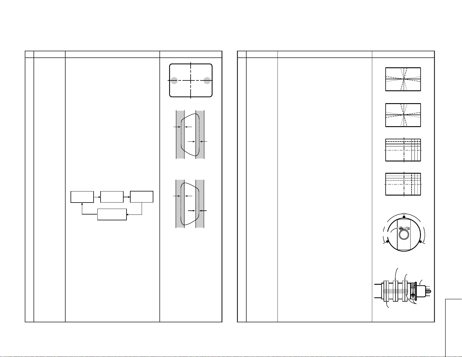
1. Adjust the overscan to 9% typical.
1. Adjust to get the best linearity.
1. Adjust the proper condition.
1. Align the screen center with the CRT's geometri-
cal center (E-5).
1. Align the screen center with the CRT's geometri-
cal center (E-5).
Note: For the V-AMP 60, V-LINEARITY 60, V-S
CORRECTION 60, V-SHIFT 60 and H-
SHIFT 60 adjustments, their corrected
data are automatically entered when the
corresponding 50 Hz mode adjustments
are made.
1The selected channels in paren-
theses have the following signals.
(E-2): crosshatch pattern (50 Hz)
signal
(E-5): monoscopepattern (50 Hz)
signal
Focus adjust-
ment 1. Receive the Monoscope Pattern signal.
2. Set to the P-NORM mode.
3. Adjust the focus control so that the screen be in
best focusing.
2
CRT CUT-OFF, SUB-CONTRAST, WHITE BALANCE AND SUB
BRIGHTNES ADJUSTMENT
No. Adjusting point Adjusting procedure/conditions Waveform and others
CRT cut-off
adjustment:
I2C bus control
adjustment
1. Receive the Monoscope Pattern signal.
2. Set to the P-NORM mode.
3. Turn on the service switch and select the "Cut-
off/background" mode.
4. Set the screen control to 0/10 position.
5. Pressthe “9” keyon the remote controllerto reach
the horizontal centering mode.
6. Turn the screen control clockwise until the hori-
zontal raster of the first glimmering colour be-
comes slightly visible.
7. Adjust the cut-off data of the other two colours
until the horizontal raster becomes whitish.
8. Turnoffthescreen control (counterclockwise) until
the horizontal raster disappears.
Note:Before starting this adjustment, warm
up the unit for 30 minutes or longer at
a beam current of over 700 µA.
9. Press the “9” key on the remote controller to call
the NORMAL mode.
1* First of all, make sure that the
R/G/B cut-off data are all initial
values.
Note:
R CUT OFF UP “1” KEY
DOWN “4” KEY
G CUT OFF UP “2” KEY
DOWN “5” KEY
B CUT OFF UP “3” KEY
DOWN “6” KEY
The data can be turned up and
down with the above keys.
1. Receive the Monoscope Pattern signal.
2. Set to the P-NORM mode.
3. Connect the DC miliammeter between TP602 (-)
and TP603 (+).
» Full Scale: 3.0mA range
4. Make sure the beam current be 1,100µA.
5. Adjust the "G-DRIVE" and "B-DRIVE" data to have
a colour temperature of 12,300°K (white).
6. Adjust the contrast and brightness control to have
a beam current of 200µA.
Ifthecolour temperature is notat12,300°K, go back
to step1 above.
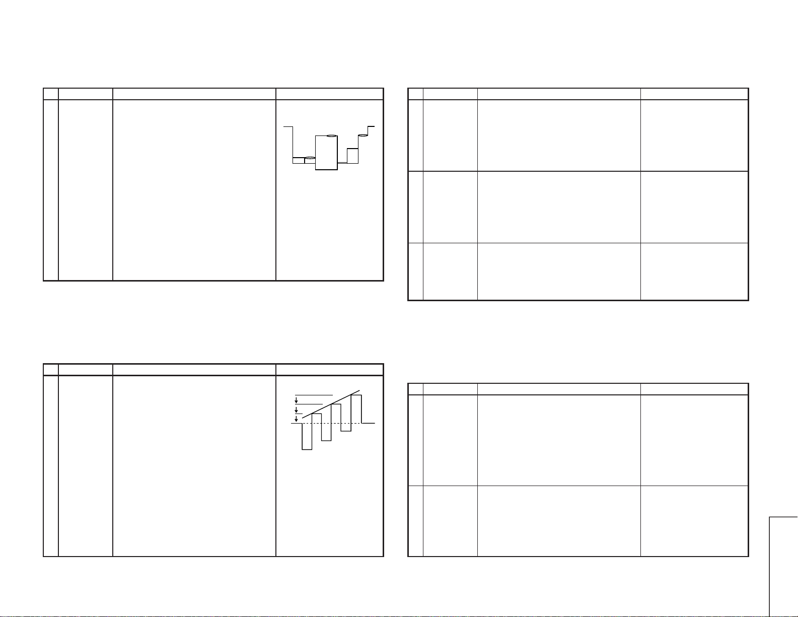
7. Receive the Crosshatch Pattern signal.
8. Adjust the "SUB BRI" bus data, so that the block
1st to 3rd inside the window area will
disappear.(black)
2Sub contrast,
white balance,
& sub bright-
ness Service
mode adjust-
ment:
I2C Bus Con-
trol Adjust-
ment
* 12,300°K X: 0.273
Y: 0.276
(with colour temperature meter
CA-100(MINOLTA).)
Note:
G-DRIVE UP “7” KEY
DOWN “-/--” KEY
B-DRIVE UP “8” KEY
DOWN “0” KEY
The data can be turned up and
down with the above keys.
1 2 3 4 5
Make sure all the 1st, 2nd
and3rd blackportions are at
the same black level.