Sharp LC32DV24U - 31.5" LCD TV User manual

In the interests of user-safety (Required by safety regulations in some countries) the set should be restored
to its original condition and only parts identical to those specified should be used.
MODEL
This document has been published to be used for
after sales service only.
The contents are subject to change without notice.
COMBINATION LIQUID CRYSTAL
TELEVISION AND DVD/CD PLAYER
CONTENTS
S68ONLC32DV24
CAUTION .............................................................................................................................
IMPORTANT SAFEGUARDS ..............................................................................................
WHEN REPLACING DVD DECK.........................................................................................
DISC REMOVAL METHOD AT NO POWER SUPPLY........................................................
PARENTAL CONTROL-RATING.........................................................................................
ABOUT LEAD FREE SOLDER (PbF) ..................................................................................
GENERAL SPECIFICATIONS .............................................................................................
DISASSEMBLY INSTRUCTIONS........................................................................................
SERVICE MODE LIST .........................................................................................................
SERVICING FIXTURES AND TOOLS.................................................................................
RE-WRITE FOR DVD FIRMWARE......................................................................................
WHEN REPLACING EEPROM (MEMORY) IC....................................................................
ELECTRICAL ADJUSTMENTS ...........................................................................................
TROUBLESHOOTING GUIDE.............................................................................................
BLOCK DIAGRAM ...............................................................................................................
PRINTED CIRCUIT BOARDS..............................................................................................
SCHEMATIC DIAGRAMS....................................................................................................
WAVEFORMS......................................................................................................................
MECHANICAL EXPLODED VIEWS ....................................................................................
DVD DECK EXPLODED VIEWS .........................................................................................
REPLACEMENT PARTS LIST.............................................................................................
Page
A1-1
A1-2~A1-4
A1-5
A1-6
A1-6
A1-7
A2-1~A2-7
B1-1~B3-2
C-1
C-2
C-2
C-3
D-1~D-6
E-1~E-9
F-1~F-8
G-1~G-10
H-1~H-52
I-1, I-2
J1-1~J1-4
J2-1
K1-1~K3-8
•
•
•
•
•
•
•
•
•
•
•
•
•
•
•
•
•
•
•
•
•
LC-32DV24U
SERVICE MANUAL
Parts marked with " " are important for maintaining the safety of the set. Be sure to replace these parts with
specified ones for maintaining the safety and performance of the set.
SHARP CORPORATION
All manuals and user guides at all-guides.com
all-guides.com

A1-1
CAUTION
THIS
LCD COLOR TELEVISION
EMPLOYS A LASER SYSTEM.
TO ENSURE PROPER USE OF THIS PRODUCT, PLEASE READ THIS SERVICE MANUAL CARE-
FULLY AND RETAIN FOR FUTURE REFERENCE. SHOULD THE UNIT REQUIRE MAINTENANCE,
CONTACT AN AUTHORIZED SERVICE LOCATION-SEE SERVICE PROCEDURE.
USE OF CONTROLS, ADJUSTMENTS OR THE PERFORMANCE OF PROCEDURES OTHER THAN
THOSE SPECIFIED HEREIN MAY RESULT IN HAZARDOUS LASER RADIATION EXPOSURE.
TO PREVENT DIRECT EXPOSURE TO LASER BEAM, DO NOT TRY TO OPEN THE ENCLOSURE.
VISIBLE LASER RADIATION MAY BE PRESENT WHEN THE ENCLOSURE IS OPENED. DO NOT
STARE INTO BEAM.
The laser diode used for a pickup head may be destroyed with external static electricity.
Moreover, even if it is operating normally after repair, when static electricity discharge is received at the
time of repair, the life of the product may be shortened.
Please perform the following measure against static electricity, be careful of destruction of a laser diode
at the time of repair.
• Place the unit on a workstation equipped to protect against static electricity, such as conductive mat.
• Soldering iron with ground wire or ceramic type is used.
• A worker needs to use a ground conductive wrist strap for body.
Location of the required Marking
The rating sheet and the safety caution are on the rear of the unit.
CERTIFICATION: COMPLIES WITH FDA
RADIATION PERFORMANCE STANDARDS,
21 CFR SUBCHAPTER J.
PREPARATION OF SERVICING
All manuals and user guides at all-guides.com

A1-2
IMPORTANT SAFEGUARDS
1) Read these instructions.
2) Keep these instructions.
3) Heed all warnings.
4) Follow all instructions.
5) Do not use this apparatus near water.
6) Clean only with dry cloth.
7) Do not block any ventilation openings. Install in accordance with the manufacturer's instructions.
8) Do not install near any heat sources such as radiators, heat registers, stoves, or other apparatus (including
amplifiers) that produce heat.
9) Do not defeat the safety purpose of the polarized or grounding-type plug. A polarized plug has two blades
with one wider than the other. A grounding type plug has two blades and a third grounding prong. The wide
blade or the third prong are provided for your safety. If the provided plug does not fit into your outlet,
consult an electrician for replacement of the obsolete outlet.
10) Protect the power cord from being walked on or pinched particularly at plugs, convenience receptacles, and
the point where they exit from the apparatus.
11) Only use attachments/accessories specified by the manufacturer.
12) Use only with the cart, stand, tripod, bracket, or table specified by the
manufacturer, or sold with the apparatus. When a cart is used, use caution when
moving the cart/apparatus combination to avoid injury from tip-over.
13) Unplug this apparatus during lightning storms or when unused for long periods
of time.
14) Refer all servicing to qualified service personnel. Servicing is required when the
apparatus has been damaged in any way, such as power-supply cord or plug is
damaged, liquid has been spilled or objects have fallen into the apparatus, the
apparatus has been exposed to rain or moisture, does not operate normally, or has been dropped.
15) Apparatus shall not be exposed to dripping or splashing and that no objects filled with liquids, such a vases,
shall be placed on the apparatus.
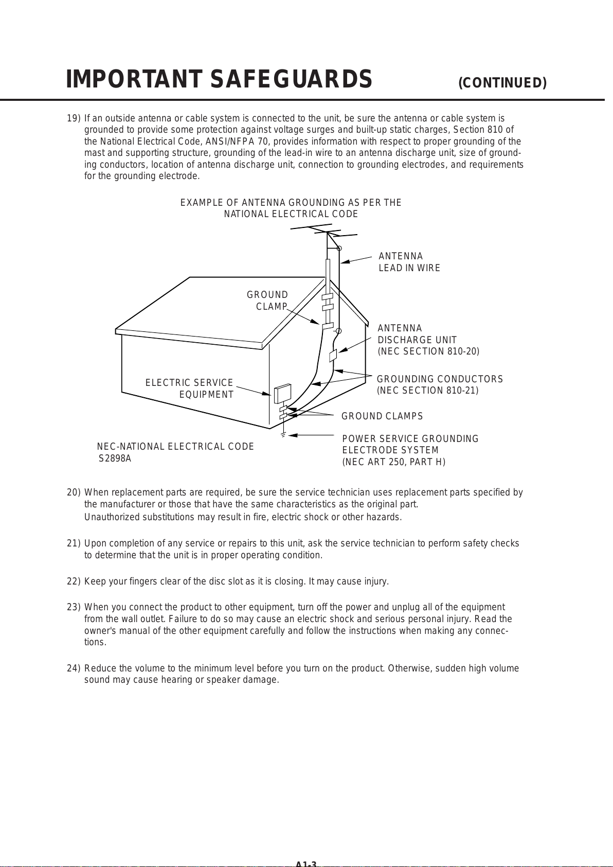
16) An outside antenna system should not be located in the vicinity of overhead power lines or other electric
light or power circuits, or where it can fall into such power lines or circuits. When installing an outside
antenna system, extreme care should be taken to keep from touching such power lines or circuits, as
contact with them might be fatal.
17) Do not overload wall outlets and extension cords, as this can result in a risk of fire or electric shock.
18) Do not push objects through any openings in this unit, as they may touch dangerous voltage points or short
out parts that could result in fire or electric shock. Never spill or spray any type of liquid into the unit.
S3126A
PORTABLECARTWARNING
(symbol provided by RETAC)
All manuals and user guides at all-guides.com

A1-3
IMPORTANT SAFEGUARDS (CONTINUED)
EXAMPLE OF ANTENNA GROUNDING AS PERTHE
NATIONAL ELECTRICAL CODE
ANTENNA
DISCHARGE UNIT
(NEC SECTION 810-20)
ANTENNA
LEAD IN WIRE
GROUNDING CONDUCTORS
(NEC SECTION 810-21)
GROUND CLAMPS
POWER SERVICE GROUNDING
ELECTRODE SYSTEM
(NEC ART 250, PART H)
GROUND
CLAMP
ELECTRIC SERVICE
EQUIPMENT
NEC-NATIONAL ELECTRICAL CODE
S2898A
19) If an outside antenna or cable system is connected to the unit, be sure the antenna or cable system is
grounded to provide some protection against voltage surges and built-up static charges, Section 810 of
the National Electrical Code, ANSI/NFPA 70, provides information with respect to proper grounding of the
mast and supporting structure, grounding of the lead-in wire to an antenna discharge unit, size of ground-
ing conductors, location of antenna discharge unit, connection to grounding electrodes, and requirements
for the grounding electrode.
20) When replacement parts are required, be sure the service technician uses replacement parts specified by
the manufacturer or those that have the same characteristics as the original part.
Unauthorized substitutions may result in fire, electric shock or other hazards.
21) Upon completion of any service or repairs to this unit, ask the service technician to perform safety checks
to determine that the unit is in proper operating condition.
22) Keep your fingers clear of the disc slot as it is closing. It may cause injury.
23) When you connect the product to other equipment, turn off the power and unplug all of the equipment
from the wall outlet. Failure to do so may cause an electric shock and serious personal injury. Read the
owner's manual of the other equipment carefully and follow the instructions when making any connec-
tions.
24) Reduce the volume to the minimum level before you turn on the product. Otherwise, sudden high volume
sound may cause hearing or speaker damage.
All manuals and user guides at all-guides.com

A1-4
HOWTO HANDLETHE LCD PANEL
• Do not press hard or jolt the LCD panel. It may cause the LCD panel glass to break and injury may occur.
• If the LCD panel is broken, make absolutely sure that you do not touch the liquid in the panel.This may
cause skin inflammation.
If the liquid gets in your mouth, immediately gargle and consult with your doctor. Also, if the liquid gets in
your eyes or touches your skin, consult with your doctor after rinsing for at least 15 minutes or longer in clean
water.
CONDENSATION
Moisture will form in the operating section of the player if the player is brought from cool surroundings into a
warm room or if the temperature of the room rises suddenly.When this happens, player's performance will
be impaired.
To prevent this, let the player stand in its new surroundings for about an hour before switching it on, or
make sure that the room temperature rises gradually.
Condensation may also form during the summer if the player is exposed to the breeze from an air condi-
tioner. In such cases, change the location of the player.
25) Do not allow the product to output distorted sound for an extended period of time. It may cause speaker
overheating and fire.
26) When you use the headphones, keep the volume at a moderate level. If you use the headphones continu-
ously with high volume sound, it may cause hearing damage.
27) Do not look into the opening of the disc slot or ventilation opening of the product to see the source of the
laser beam. It may cause eye damage.
28) Do not use a cracked, deformed, or repaired disc. These discs are easily broken and may cause serious
personal injury and product malfunction.
29) This reminder is provided to call the cable TV system installer's attention to Article 820-40 of the NEC that
provides guidelines for proper grounding and, in particular, specifies that the cable ground shall be con-
nected to the grounding system of the building, as close to the point of cable entry as practical.
IMPORTANT SAFEGUARDS (CONTINUED)
All manuals and user guides at all-guides.com

A1-5
Before removing Pick Up PCB and DVD MT PCB connector, the short circuit the position shown in Fig.
1using a soldering iron. If you remove the DVD Deck with no soldering, the Laser may be damaged.
WHEN REPLACING DVD DECK
[ When removing the DVD Deck ]
[ When installing the DVD Deck ]
Remove all the soldering on the short circuit position after the connection of Pick Up PCB and DVD
MT PCB connector.
NOTE
Fig. 1
Before your operation, please read “PREPARATION OF SERVICING”.
Use the Lead Free solder.
Manual soldering conditions
• Soldering temperature: 320 ± 20oC
• Soldering time: Within 3 seconds
• Soldering combination: Sn-3.0Ag-0.5Cu
When Soldering/Removing of solder, use the draw in equipment over the Pick Up Unit to keep the
Flux smoke away from it.
•
•
•
•
Short circuit using a
soldering iron.
Pick Up PCB
All manuals and user guides at all-guides.com
all-guides.com

A1-6
1.
2.
3.
Remove the Back Cabinet and Angle Deck. (Refer to item 1 of the DISASSEMBLY INSTRUCTIONS.)
Slide the Belt Loading toward the arrow direction by hand to release the lock. (Refer to Fig. 1)
Take out the Disc from the DVD Deck. Be careful not to scratch on the Disc.
DISC REMOVAL METHOD AT NO POWER SUPPLY
Fig. 1
DVD Deck
Belt Loading
If the stored 4 digit password in the Rating Level menu needs to be cancelled, please follow the steps below.
Turn Unit ON.
Set the DVD to the Stop Mode.
Check that “No disc” is displayed on the screen.
Press and hold the “STOP” button on the top panel.
Simultaneously press and hold the “7” key on the remote control unit.
Hold both keys for more than 2 seconds.
The On Screen Display message “PASSWORD CLEAR” will appear.
The 4 digit password has now been cleared.
1.
2.
3.
4.
5.
6.
7.
8.
PARENTAL CONTROL - RATING LEVEL
4 DIGIT PASSWORD CANCELLATION
All manuals and user guides at all-guides.com

PCBs (manufactured) using lead free solder will have a PbF printing on the PCB.
(Please refer to figures.)
Caution:
Pb free solder has a higher melting point than standard solder;
Typically the melting point is 86°F~104°F(30°C~40°C) higher.
Please use a soldering iron with temperature control and adjust it to 650°F ± 20°F (350°C ± 10°C).
In case of using high temperature soldering iron, please be careful not to heat too long.
Pb free solder will tend to splash when heated too high (about 1100°F/ 600°C).
All products with the printed circuit board with PbF printing must be serviced with lead free solder.
When soldering or unsoldering, completely remove all of the solder from the pins or solder area,
and be sure to heat the soldering points with the lead free solder until it melts sufficiently.
Distinction of PbF PCB:
Recommendations
Recommended lead free solder composition is Sn-3.0Ag-0.5Cu.
ABOUT LEAD FREE SOLDER (PbF)
•
•
•
A1-7
All manuals and user guides at all-guides.com

GENERAL SPECIFICATIONS
G-1 TV LCD LCD Size / Visual Size 31.5 inch / 800.4mmV
System LCD Type Color TFT LCD
Number of Pixels 1366(H) x 768(V)
View Range Left/Right 88/88 degree
Up/Down 88/88 degree
Bright Dot n=2
Zero Bright Dot Ratio --
Color System NTSC
Speaker 2 Speaker
Position Front
Size 1.6 x 4.8 inch
Impedance 8 ohm
Sound Output Max 5.0W + 5.0W
10%(Typical) ---
G-2 DVD System Color System NTSC
Disc DVD, CD-DA, CD-R/RW
DVD-R/RW (Video Format Only)
Disc Diameter 120 mm , 80 mm
Drive DSM-2
Search speed Fwd 4 step
Actual 2-45 times (DVD)
4-40 times (CD)
Rev 4 step
Actual 2-45 times (DVD)
4-40 times (CD)
Slow speed Fwd 1/7 -1/2 times
Actual --
Rev 1/7 -1/2 times
Actual --
G-3 Tuning Broadcasting System Analog US System M
System Digital ATSC(8VSB)/QAM
Tuner and System 1Tuner
Receive CH Destination US (W/CABLE)
CH Coverage 2~69, 4A, A-5~A-1, A~I, J~W, W+1~W+84
Intermediate
Digital 44.00MHz
Frequency Analog Picture(FP) 45.75MHz
Sound(FS) 41.25MHz
FP-FS 4.50MHz
Preset CH No
Stereo/Dual TV Sound US-Stereo
Tuner Sound Muting Yes
G-4 Signal Video Signal Input Level 1 V p-p/75 ohm
Output Level --
S/N Ratio (Weighted) --
Horizontal Resolution at DVD Mode --
--
RGB Signal Output Level --
Audio Signal Input Level 0.85 V p-p/50k ohm
Output Level at DVD 0.56 V p-p/ 1k ohm (-20dBFs, 0dBFs=5.6 V p-p)
at TV 0-1.7 V p-p/1k ohm
Digital Output Level 0.5 V p-p/75 ohm
S/N Ratio at DVD (Weighted) 85dB
Harmonic Distortion 0.02% (1KHz)
Frequency Response : at DVD 4 Hz - 44 KHz (96KHz)
at Video CD --
at SVCD --
at CD 4 Hz - 20 KHz
<
A2-1
All manuals and user guides at all-guides.com

GENERAL SPECIFICATIONS
G-5 Power Power Source AC 120V, 60Hz
DC --
Power Consumption at AC 170W at 120V 60Hz
at DC --
Stand by (at AC) 0.8W at 120V 60Hz
Energy Star Yes
Per Year -- kWh/Year
Protector Power Fuse Yes
Safety Circuit Yes
IC Protector(Micro Fuse) Yes
G-6 Regulation Safety UL(UL6500_2nd)/CSA(E60065_00)
Radiation FCC / IC
Laser DHHS
G-7 Temperature Operation
+5
o
C ~ +40
o
C
Storage
-20
o
C ~ +60
o
C
Space Around Unit 100 mm(4inch)
G-8 Operating Humidity Less than 80% RH
G-9 Clock and Clock No
Timer Sleep Timer Max Time 120 Min
On Timer Program No
Off Timer Program No
Game Timer No
Wake Up Timer No
Timer Back-up (at Power Off Mode) more than -- Min Sec
A2-2
All manuals and user guides at all-guides.com

GENERAL SPECIFICATIONS
G-10 Remote Unit RC-MR
Control Glow in Dark Remocon No
Remocon Format SHARP
Format TV:SHARP, DVD:KASEIKYO
Custom Code TV:SHARP 15bit, DVD:KASEIKYO 48bit
Power Source Voltage(D.C) 3V
UM size x pcs UM-3 x 2 pcs
Total Keys 47 Keys
Keys
POWER Yes
DISPLAY Yes
SLEEP Yes
VIEW MODE Yes
INPUT SELECT Yes
1Yes
2Yes
3Yes
4Yes
5Yes
6Yes
7Yes
8Yes
9Yes
0Yes
MUTE Yes
AUDIO Yes
VOL+ Yes
VOL- Yes
CH+ Yes
CH- Yes
LEFT/SLOW- Yes
ENTER Yes
RIGHT/SLOW+ Yes
UP Yes
DOWN Yes
SETUP/TV MENU Yes
EXIT/CANCEL Yes
RETURN Yes
/SUBTITLE Yes
TV/DVD Yes
OPEN/CLOSE(EJECT) Yes
FWD(SEARCH+) Yes
REV(SEARCH-) Yes
SKIP+ Yes
SKIP- Yes
PAUSE/STILL Yes
PLAY Yes
STOP Yes
PLAY MODE Yes
ANGLE Yes
ZOOM Yes
DVD MENU Yes
TOP MENU Yes
REPEAT A-B Yes
MARKER Yes
DIRECT SKIP(JUMP) Yes
FREEZE No
.
A2-3
All manuals and user guides at all-guides.com
all-guides.com

GENERAL SPECIFICATIONS
G-11 Features Auto Shut Off Yes
(TV) Auto Search No
Power On Memory Yes
Comb Filter Yes
3 -D
Game Position No
Auto Setup(Language/CH Program) No
Picture Setting(TV) Yes
AV Mode(Picture Preference) Yes
Brightness , Contrast , Color Yes
Tint Yes
Sharpness Yes
Color Temperature Yes
DNR Yes
Cable Clear No
Picture Setting(PC) Yes
HOR Position , VER Position Yes
Phase, Clock Yes
Red, Green, Blue No
Auto Adjust No
Backlight No
Audio MTS Yes
Tone Control (Bass/Treble/Balance) Yes
Stable Sound No
Surround No
BBE No
SRS WOW (SRS 3D/Focus/Tru Bass) No
Variable Audio Out Yes
Tuning CH Program Yes
Air/Cable Yes
ADD/DELETE Yes
Label CH Label Yes
Video Label Yes
Favorite CH No
V-Chip Yes
Type USA/CANADA Type
RRT Setup
Yes
Lock Hotel Lock No
Channel Lock No
Video Lock No
Panel Lock No
Menu Language English
French
Spanish
Closed Caption
Yes
CC Advanced
Yes
View Mode (Picture Size) Yes
Picture Scroll
No
Film Mode Yes
Aspect
No
Backlight Yes
PFC(Power Factor circuit)
No
Freeze frame No
PIP/POP No
Direct Input Selection Yes
Digital Out Dolby Digital Yes
MPEG No
PCM No
DTS No
PC Monitor Input Yes
VGA (640x480) Yes (60Hz)
VGA (720x400) Yes (70Hz)
WVGA (848x480) No
SVGA (800x600) Yes (60Hz)
XGA (1024x768) Yes (60Hz)
WXGA (1280x768) Yes (60Hz)
WXGA (1280x720) Yes (60Hz)
WXGA (1360x768) Yes (60Hz)
SXGA (1280x1024) No
WXGA+ (1440x900) No
A2-4
All manuals and user guides at all-guides.com

GENERAL SPECIFICATIONS
HDMI Input Yes
VGA (640×480) Yes (60Hz)
720×480i (4:3) Yes (60Hz)
720×480i (16:9) Yes (60Hz)
720×480p (4:3) Yes (60Hz)
720×480p (16:9) Yes (60Hz)
720×576i (4:3) No
720×576i (16:9) No
720×576p (4:3) No
720×576p (16:9) No
1280×720p Yes (60Hz)
1920×1080i Yes (60Hz)
CEC (ORION Standard) No
Deep Color No
xvYCC No
Component Input Yes
720×480i (4:3) Yes (60Hz)
720×480i (16:9) Yes (60Hz)
720×480p (4:3) Yes (60Hz)
720×480p (16:9) Yes (60Hz)
720×576i (4:3) No
720×576i (16:9) No
720×576p (4:3) No
720×576p (16:9) No
1280×720p Yes (60Hz)
1920×1080i Yes (60Hz)
Wall Mount Size W x H(mm) Yes (200 x 200)
Screw Size M6 x 10
Features Video CD Playback No
(DVD) SVCD Playback
No
MP3 Playback Yes
JPEG Yes
WMA Yes
Digital Out (Dolby Digital) Yes
(MPEG) Yes
(PCM) Yes
(DTS) Yes
Down Mix Out (Dolby Digital) Yes
(DTS) No
Closed Caption Yes
Screen Saver No
TV Screen 4:3 (Letter Box, Pan Scan) Yes
16:9 (Wide) Yes
Audio DAC 192kHz / 24bit
A2-5
All manuals and user guides at all-guides.com

GENERAL SPECIFICATIONS
G-12 Accessories Owner's Manual Language English/French/Spanish
w/Guarantee Card Yes
Remote Control Unit Yes
Rod Antenna
No
Poles --
Terminal --
Loop Antenna
No
Terminal --
U/V Mixer
No
DC Car Cord (Center+)
No
Guarantee Card
No
Warning Sheet
No
Circuit Diagram
No
Antenna Change Plug
No
Service Facility List
No
Important Safeguard
No
Dew/AHC Caution Sheet
No
Quick Set-up Sheet
No
Battery Yes
UM size x pcs UM-3 x 2 pcs
OEM Brand No
AC Adapter
No
AC Cord (for AC Adapter)
No
AC Cord (Flat Polarity Plugs) Yes
Cable Cramp Yes
Stand Yes
Stand Screw Yes
Hexagon Wrench Yes
AV Cord (2Pin-1Pin)
No
Registration Card (NDL Card) Yes
300 to 75ohm Antenna Adapter
No
Sheet Information (Return) No
Sheet Information (HDMI)
No
Sheet Information (CEA) Yes
Sheet Information(FCC) Yes
Cleaning Cloth No
G-13 Interface Switch Top Power (Tact) Yes
Channel Up Yes
Channel Down Yes
Volume Up Yes
Volume Down Yes
Menu No
Play Yes
Eject Yes
Skip+, Search+ Yes
Skip-, Search- Yes
Still/Pause No
Stop Yes
Main Power SW No
Input Select Yes
Rear Main Power SW No
Indicator Power/Stand-By Yes (Green / Red)
Power Wake Up No
On Timer No
A2-6
All manuals and user guides at all-guides.com

GENERAL SPECIFICATIONS
Terminals Side Video Input 1 RCA x 1
Audio Input 1 RCA x 2(L/MONO, R)
S - Input 1 Yes
Video Input 2 RCA x 1
Audio Input 2 RCA x 2(L/MONO, R)
S - Input 2 No
Video Output No
Audio Output RCA x 2 (Variable) (L, R)
Component Input 1 RCA x 3
Analog Audio Video Input 2 Audio Input Alternative
Component Input 2 No
Analog Audio No
HDMI Input 1 Yes
Analog Audio PC Monitor Audio Input Alternative
HDMI Input 2 No
Analog Audio No
Sub Woofer Out No
PC Monitor Input Yes
Analog Audio Mini Pin Jack( 3.5), STEREO
Digital Audio Output Coaxial
DC Jack (Center +) No
VHF/UHF Antenna Input F Type
Video Input 3 No
Audio Input 3 No
S - Input 3 No
Other Terminal No
AC Inlet Yes
G-14 Set Size Approx. W x D x H (mm) 797 x 243 x 583
w/o Handle, Stand Approx. W x D x H (mm) 797 x 116 x 534
G-15 Weight Net (Approx.) 14.5kg (32.4lbs)
Net w/o Handle, Stand (Approx.) 13.0kg (29.2lbs)
Gross (Approx.) 17.5kg (39.0lbs)
G-16 Carton Master Carton No
Content --- Sets
Material --- / ---
Dimensions W x D x H(mm) ---
Description of Origin ---
Gift Box Material Double/Brown
W/Color Photo Label No
W/Handle No
Dimensions W x D x H(mm) 900 x 286 x 659
Description of Origin Yes
Drop Test 1 Corner / 3 Edges / 5 Surfaces
Height (cm) 32
Container Stuffing (40' container) 321
Sets/40' container
w/Pallet No
w/Wrapping No
G-17 Material Cabinet Front PC+ABS 94V0 NON-HALOGEN
Rear PS 94V0 NON-DECABROM
Jack Panel --
PCB Non-Halogen Demand No
Eyelet Demand Yes
G-18 Environment Environmental standard requirement Green procurement of SHARP
Pb-free Phase3(Phase3A)
Measures for Whisker Yes
Rohs Yes
A2-7
All manuals and user guides at all-guides.com

DISASSEMBLY INSTRUCTIONS
B1-1
1. REMOVAL OF MECHANICAL PARTS
AND P.C. BOARDS
CAUTION
Be careful not to remove the FFC cable forcibly, because
the FFC cable may be damaged.
Fig. 1-1
Back Cabinet
(1)
(1)
(1)
(1)
(1)
(1)
(2) (2)
(2)
(2)
(2)
(1)
(1)
(2)
(1)
(1)
(2)
(1)
(1) (1)
1-2: DVD MT PCB/DVD DECK (Refer to Fig. 1-2)
1.
2.
3.
4.
5.
6.
7.
8.
9.
10.
11.
12.
13.
14.
Short circuit the position shown in Fig. 1-2 using a
soldering iron. If you remove the DVD Deck with no
soldering, the Laser may be damaged.
Disconnect the following connectors:
(CP403 and CP4301).
Remove the screw (1).
Remove the DVD Deck in the direction of arrow (A).
Remove the 2 screws (2).
Remove the screw (3).
Remove the Angle DVD-1 in the direction of arrow (B).
Remove the 2 screws (4).
Remove the Heat Sink in the direction of arrow (C).
Remove the 2 screws (5).
Remove the Angle MPEG in the direction of arrow (D).
Disconnect the following connectors:
(CP2301, CP2302 and CP2303).
Remove the 4 screws (6).
Remove the DVD MT PCB in the direction of arrow (E).
1-1: BACK CABINET (Refer to Fig. 1-1)
1.
2.
3.
Remove the 13 screws (1).
Remove the 7 screws (2).
Remove the Back Cabinet in the direction of arrow.
NOTE
Before your operation, please read "PREPARATION
OF SERVICING".
Use the Lead Free solder.
Manual soldering conditions
• Soldering temperature: 320 ± 20oC
• Soldering time: Within 3 seconds
• Soldering combination: Sn-3.0Ag-0.5Cu
When Soldering/Removing of solder, use the drawing
equipment over the Pick Up Unit to keep the Flux
smoke away from it.
When installing the DVD Deck, remove all the soldering
on the short circuit position after the connection of Pick
Up PCB and DVD MT PCB connector.
1.
2.
3.
4.
5.
Fig. 1-2
(A)
Pick Up PCB
DVD MT PCB
(2) DVD Deck
(2)
Angle MPEG
Short circuit using
a soldering iron.
(5)
(3) (B)
(E)
(5)
(6)
(6)
(6)
(6)
(1)
(D)
1.
2.
3.
4.
5.
6.
7.
Disconnect the following connector: (CP6202).
Remove the Plate Button Ass'y in the direction of
arrow (A).
Remove the 6 screws (1).
Remove the Operation PCB and Operation 2 PCB in the
direction of arrow (B).
Remove the 2 screws (2).
Remove the 5 screws (3).
Remove the Angle Hinge in the direction of arrow (C).
OPERATION PCB/OPERATION2 PCB and
ANGLE HINGE (Refer to Fig. 1-3)
1-3:
Heat Sink
Angle DVD-1
(4) (4)
(C)
Fig. 1-3
Operation PCB
Plate Button Ass'y
(B)
(A)
(2)
(3)
Operation 2 PCB
(C)
(2)
Angle Hinge
(3)
(3) (3)
(3)
(1)
(1)
(1)
(1)
(1)
(1)
(A)
All manuals and user guides at all-guides.com
all-guides.com

DISASSEMBLY INSTRUCTIONS
B1-2
Fig. 1-6
1-7: POWER PCB (Refer to Fig. 1-7)
1.
2.
3.
4.
5.
6.
Disconnect the following connectors:
(CP302 and CP406).
Remove the Holder Wire and Spring Earth.
Remove the 6 screws (1).
Remove the Power PCB in the direction of arrow (A).
Remove the screw (2).
Remove the Angle PCB-1 in the direction of arrow (B).
(B)
(A)
(1)
(2)
Digital PCB
(3)
Plate Jack
Shield Digital
(4) (5)
1-4: REMOCON PCB (Refer to Fig. 1-4)
1.
2.
3.
Disconnect the following connector:
(CP4201).
Remove the 2 screws (1).
Remove the Remocon PCB in the direction of arrow.
(5)
(5)
(5)
(5)
(5)
(2)
Fig. 1-4
Remocon PCB
(1)
(1)
1-5: LCD BLOCK (Refer to Fig. 1-5)
1.
2.
3.
4.
5.
Remove the Holder Panel-1 and Holder Panel-2.
Remove the 4 screws (1).
Remove the LCD Block in the direction of arrow.
Remove the 2 screws (2).
Remove the Angle Main.
Fig. 1-5
(1) (1)
(1)
(1)
LCD Block
Angle Main
(2)
(2)
Angle Main
1-6: DIGITAL PCB (Refer to Fig. 1-6)
1.
2.
3.
4.
5.
6.
7.
8.
Disconnect the following connectors:
(CP2804, CP3001 and CP4302).
Remove the screw (1).
Remove the 5 screws (2).
Remove the 2 screws (3).
Remove the screw (4).
Remove the Plate Jack in the direction of arrow (A).
Remove the 6 screws (5).
Remove the Digital PCB and Shield Digital in the
direction of arrow (B).
Holder Panel-2
Holder Panel-2
Holder Panel-1
Fig. 1-7
Power PCB
(1)
(1) (1)
(1)
(1) (1)
(A)
(B)
Angle PCB-1
(2)
Holder Wire
Holder Wire Spring Earth
All manuals and user guides at all-guides.com

DISASSEMBLY INSTRUCTIONS
B1-3
1-8: ANGLE LCD TOP/ANGLE LCD BOTTOM AND
ANGLE PCB-2 ASS'Y (Refer to Fig. 1-8)
1.
2.
3.
4.
5.
6.
Remove the 3 screws (1).
Remove the Angle Pcb-2 Ass'y and Holder Wire in the
direction of arrow (A).
Remove the 2 screws (2).
Remove the Angle Lcd Bottom and Holder Wire in the
direction of arrow (B).
Remove the 2 screws (3).
Remove the Angle Lcd Top and Holder Wire in the
direction of arrow (C).
(1)
(1)
(A)
LCD Panel
Fig. 1-8
(1)
Holder Wire
(2)
(2)
(3)
(3)
Holder Wire
Holder Wire
Angle Lcd Top
Angle Lcd Bottom
Holder Wire
(B)
(C)
Holder Wire
Angle Pcb-2 Ass'y
All manuals and user guides at all-guides.com

DISASSEMBLY INSTRUCTIONS
B2-1
2. REMOVAL OF DVD DECK PARTS
2-1: TRAVERSE ASS'Y (Refer to Fig. 2-1-A)
Remove the 3 screws (1).
Unlock the 2 supports (2).
Remove the Insulator (R) from the Loader Sub Ass'y.
Remove the Traverse Ass'y.
1.
2.
3.
4.
Fig. 2-1-A
Insulator (R)
NOTE
1. Disassemble only the DVD DECK PARTS parts listed
here. Minute adjustments are needed if the
disassembly is done. If the repair is needed except
listed parts, replace the DVD MECHA ASS'Y.
(1)
(2)
Loader Sub Ass'y
Traverse Ass'y
(2)
Fig. 2-1-B
• Screw Torque: 2.0 ± 0.3kgf•cm (1)
(1)
NOTE
1. In case of the Traverse Ass'y installation, hook the wire
on the Loader Ass'y as shown Fig. 2-1-B to Fig. 2-1-D.
2-2:
Remove the Insulator (F).
Remove the Insulator (R).
Unlock the support (1).
Remove the Gear Middle.
Remove the screw (2).
Remove the Rack Feed Ass'y.
Remove the screw (3).
Remove the Switch PCB Ass'y.
Remove the screw (4).
Remove the Gear Feed.
Remove the 2 screws (5).
Remove the Feed Motor.
Remove the Gear Motor.
1.
2.
3.
4.
5.
6.
7.
8.
9.
10.
11.
12.
13.
SWITCH PCB ASS'Y/GEAR MIDDLE/GEAR FEED/RACK
FEED ASS'Y/FEED MOTOR (Refer to Fig. 2-2-A)
(3)
Gear Middle
Gear Motor
Feed Motor
• Screw Torque: 1.3 ± 0.3kgf•cm (Screw (2))
• Screw Torque: 3.0 ± 0.3kgf•cm (Screw (3))
• Screw Torque: 1.0 ± 0.3kgf•cm (Screw (4), (5))
Switch PCB Ass'y
(2)
(4)
Rack Feed Ass'y
Gear Feed
(5)
Fig. 2-2-A
Traverse Ass'y
(5)
(1)
Insulator (R)
Insulator (F)
Insulator (F)
NOTE
1.
2.
3.
4.
When installing the Rack Feed Ass'y, push both ends to
align the teeth as shown Fig. 2-2-B. Then install it.
In case of the Gear Motor installation, check if the value
of the Fig. 2-2-C is correct.
When installing the wire of the Switch PCB Ass'y, install
it correctly as Fig. 2-2-D.
Manual soldering conditions
• Soldering temperature: 320 ± 20oC
• Soldering time: Within 3 seconds
• Soldering combination: Sn-3.0Ag-0.5Cu
After the assembly of the Traverse Ass'y, hook the wire
on the Traverse Ass'y as shown Fig. 2-2-E.
[OK] [NG]
Fig. 2-2-B
Rack Feed Ass'y
Push
Push
Fig. 2-1-D
Loader Ass'y (Top Side)
Check Hook
Loader Ass'y (Bottom Side)
Check Lock Check Lock
Check Hook Check Hook
Fig. 2-1-C
Loader Ass'y
80 ± 5mm
Check Hook
All manuals and user guides at all-guides.com

DISASSEMBLY INSTRUCTIONS
B2-2
When installing the FFC, fold it correctly and install it as
shown from Fig. 2-3-A to Fig. 2-3-B.
2-3: FFC WIRE HANDLING
1.
Do not make the folding lines except the specified
positions for the FFC.
1.
NOTE
Traverse Ass'y
Check Hook
Check Hook
Check Hook
Fig. 2-2-E
• Loosen the wire in the direction of the arrow.
Check Hook
~ FEED MOTOR ~
WHITE (4)
BROWN (3)
~ SPINDLE MOTOR ~
YELLOW (2)
GREEN (1)
Fig. 2-2-D
Switch PCB Ass'y
• Install wire from (1) to (4) in order.
Fold
40 ± 1mm
Fig. 2-2-C
8.0 ± 0.2mm
Safety surface for pressing
of the insert.
Feed Motor
Gear Motor
[ 6 pin FFC ]
Fig. 2-3-B
Fold
60 ± 1mm
To Pick Up PCB Printing Surface
Fold it by 90o
20 ± 1mm
[ 24 pin FFC ]
Fig. 2-3-A
30 ± 1mm
All manuals and user guides at all-guides.com
Other manuals for LC32DV24U - 31.5" LCD TV
1
Table of contents
Other Sharp TV manuals

Sharp
Sharp 21H-FG5RU User manual

Sharp
Sharp 2T-C40AE1X User manual

Sharp
Sharp 28LW-92H User manual

Sharp
Sharp 54DS05SN User manual

Sharp
Sharp CX51N3 User manual

Sharp
Sharp 4T-C70BK2UD User manual

Sharp
Sharp 33ML400 User manual

Sharp
Sharp 25WG3 User manual

Sharp
Sharp 8C221 User manual

Sharp
Sharp LC-50LE650V Manual

Sharp
Sharp DV-3750S User manual

Sharp
Sharp LC-43SFE7451E User manual

Sharp
Sharp 37EM-33H User manual

Sharp
Sharp 32U-S50B User manual

Sharp
Sharp 14BM2 User manual

Sharp
Sharp LC-40FG5241K User manual

Sharp
Sharp 21J-FV1RU User manual

Sharp
Sharp LC-24DC50M User manual

Sharp
Sharp C-2890EES User manual

Sharp
Sharp 29H-FX3M User manual