Ref. No. Part No. ★Description Code Ref. No. Part No. ★Description Code
10
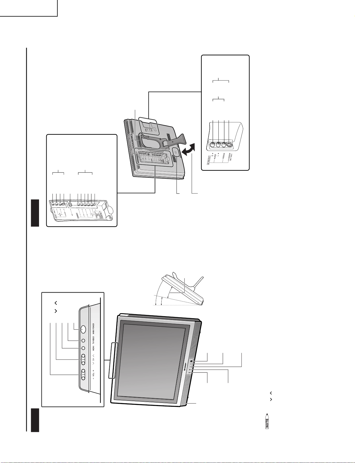
LC-13S1U-B
LC-13S1U-W
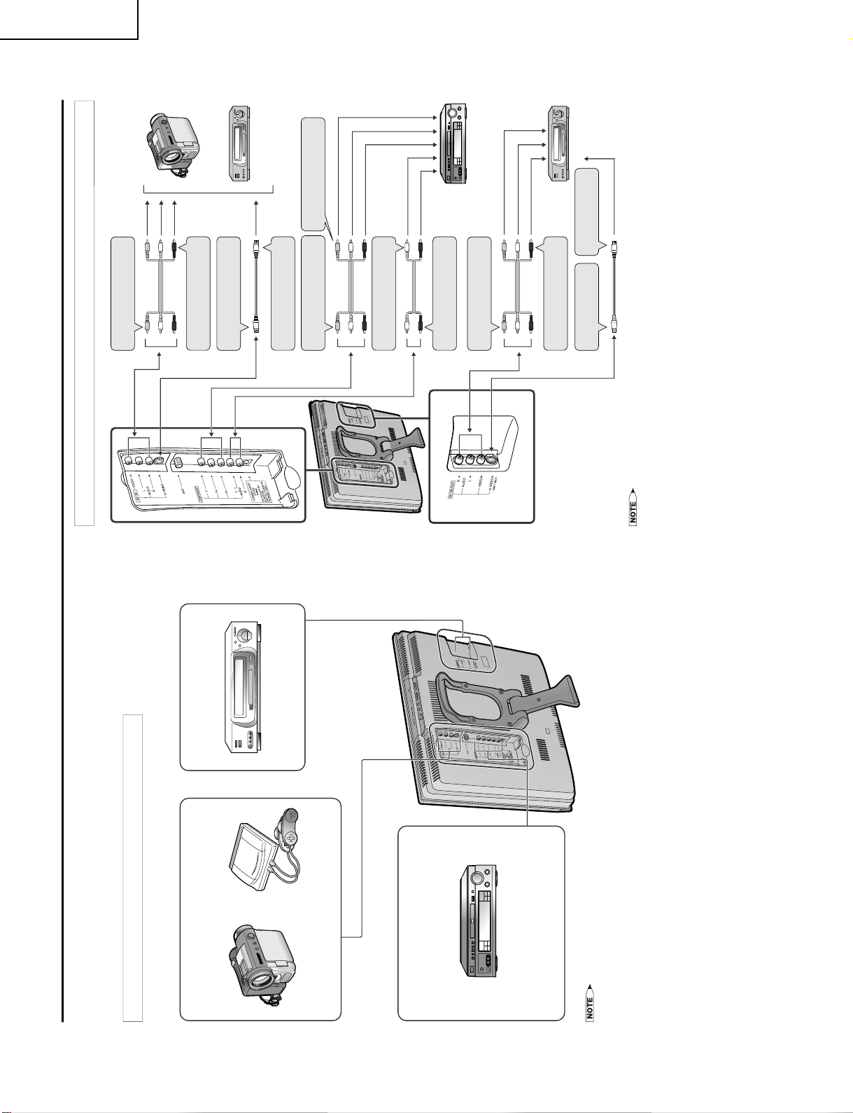
CABINET AND MECHANICAL PARTS
★ MARK: SPARE PARTS-DELIVERY SECTION ★ MARQUE: SECTION LIVRAISON DES PIECES DERECHANGE
PARTS LIST
PARTS REPLACEMENT
Replacementpartswhichhave these specialsafetycharacteristicsiden-
tified in this manual ; electrical components having such features are
identified by åand shaded areas in the Replacement Parts Lists and
Schematic Diagrams. The use of a substitute replacement part which
doesnohave thesamesafety characteristicasthe factoryrecommended
replacement parts shown in this service manual may create shock, fire
or other hazards.
"HOW TO ORDER REPLACEMENT PARTS"
To have your order filled promptly and correctly, please furnish the fol-
lowing informations.
1. MODEL NUMBER 2.REF.NO.
3. PART NO. 4. DESCRIPTION
in USA: Contact your nearest SHARP Parts Distributor to order. For
location of SHARP Parts Distributor, Please call Toll-Free;
1-800-BE-SHARP
LISTE DES PIECES
CHANGE DES PIECES
Les pi`eces de rechange qui pr élelesentent ces caract éleristiques sp
élecialesdes élecuritéle,sontidentifi éleesdansce manuel :les pi`eces
élelectriques qui pr élesentent ces particularit éles, sont rep éler élee
parlamarqueået sont hachur élees dans les listes de pi`ecesetdans
les diagrammes sch élematiques.
Lasubstitutiond'unepi`ecede rechangeparune autrequine préLesente
pas les m éoemes caract éLeristiques de s élecurit éle que la pi`ece
recommandéleeparl'usine etdansce manueldeservice, peutprovoquer
une éLelectrocution, un incendie ou toutautre sinistre.
"COMMENT COMMANDER LES PIECES DE RECHANGE"
Pour que votre commande soit rapidement et correctement remplie,
veuillez fournir les renseignements suivants.
1. NUMERO DU MODELE 2. NO. DE REF
3. NO. DE PIECE 4. DESCRIPTION
in CANADA: Contact SHARP Electronics of Canada Limited
Phone (416) 890-2100
Ref. No. Part No. ★Description Code Ref. No. Part No. ★Description Code
1 CCABAA375WJ02 J Cabinet AAss’y BD
(LC-13S1U-B)
1 CCABAA375WJ03 J Cabinet AAss’y BC
(LC-13S1U-W)
1-1
Not Available
– Cabinet A —
1-2 HDECQA269WJSA J R/C, LED Cover AE
1-3 PSPAHA061WJZZ J Spacer(L), x2 AC
1-4 PSPAHA062WJZZ J Spacer(S), x2 AC
1-5 QCNW-B662WJQZ J Connecting Cord(SP) AH
1-6 QEARZ0047CEZZ J Grounding Part AC
1-7 VSP7530PB628B J Speaker, x2 AN
1-8 XEBSN30P08000 J Screw, x6 AA
1-9 TLABZA635WJZZ J "Energy Star" Label AC
1-10 TLABZA459WJZZ J "POP" Label AB
2 CCABBA270WJ02 J Cabinet B Ass’y AZ
(LC-13S1U-B)
2 CCABBA270WJ03 J Cabinet B Ass’y AZ
(LC-13S1U-W)
2-1
Not Available
– Cabinet B —
2-2 GLEGGA027WJSA J Rubber Leg, x2 AF
2-3 HiNDPA544WJSA J Model Label(LC-13S1U-B) AE
2-3 HiNDPA545WJSA J Model Label(LC-13S1U-W) AE
2-4 JBTN-A183WJKA J Operation Button AK
2-5 JBTN-A186WJKA J Power Button AF
2-6 LANGF2155CEFW J Round Lock AD
2-7 LANGTA080WJFW J Reinforcement Angle AM
2-8 MSPRCA015WJFW J Power Button Spring AB
2-9 PMLT-A091WJZZ J Light Shielding Spacer, x1 AC
2-10 PMLT-0402CEZZ J Light Shielding Spacer, x1 AC
2-11 XEBSN30P08000 J Screw, x3 AA
3 CDAi-A089WJ01 J Stand Ass’y(LC-13S1U-B) BC
3 CDAi-A089WJ05 J Stand Ass’y(LC-13S1U-W) BB
3-1 CDAi-A089WJ02 J Stand Base Ass’y AZ
(LC-13S1U-B)
3-1 CDAi-A089WJ06 J Stand Base Ass’y AZ
(LC-13S1U-W)
3-1-1 Not Available – Stand Base —
3-1-2 GLEGGA029WJSA J Rubber Leg, x1 AF
3-1-3 PSPAZA083WJZZ J Spacer, x2 AB
3-2 JHNDPA004WJSA J Stand Handle AT
3-3 XESSN40P10000 J Screw, x8 AB
4
Not Available
– 13” LCD Panel Unit Ass’y —
4-1 RLCDTA023WJZZ J 13” LCD Panel Unit CQ
4-2
Not Available
– Back Shield Ass’y —
4-2-1 PSLDMA253WJFW J Back Shield AP
4-2-2 TCAUZA031WJZZ J Caution Label AB
å4-3 KLMP-0120CEZZ J Lamp Unit BD
4-4 PGiDMA010WJZZ J Light Guide Plate AY
4-5 PMiR-0292CEZZ J Reflection Mirror(L), x2 AG
4-6 PMiR-0293CEZZ J Reflection Mirror(S), x2 AF
4-7 PSHEP0276CEZZ J Reflection/deflection Sheet BB
4-8 PSHEPA143WJZZ J Prism Sheet AV
4-9 PSHEP0278CEZZ J Diffuison Sheet AL
4-10 PSHEP0279CEZZ J Reflection Sheet-1 AG
4-11 PSHEP0280CEZZ J Reflection Sheet-2 AG
4-12 PSHEP0306CEZZ J Reflection Sheet(Cover) AC
4-13 PSLDMA284WJZZ J Shield, x2 AE
4-14 PSPAKA014WJZZ J Spacer, x1 AD
4-15 QCNW-B531WJQZ J Connecting Cord AD
4-16 QCNW-B532WJQZ J Connecting Cord AF
4-17 QCNW-B779WJQZ J Connecting Cord AE
4-18 PMLT-A074WJZZ J Light Shielding Spacer, x1 AD
5 GCOVAA502WJKA J Terminal Cover AH
(LC-13S1U-B)
5 GCOVAA502WJKC J Terminal Cover AH
(LC-13S1U-W)
6 GCOVAA505WJKA J Bass Cone Cover AD
(LC-13S1U-B)
6 GCOVAA505WJKC J Bass Cone Cover AB
(LC-13S1U-W)
7 LCHSMA050WJKA J Chassis Frame(R) AK
(LC-13S1U-B)
7 LCHSMA050WJKC J Chassis Frame(R) AK
(LC-13S1U-W)
8 LCHSMA055WJKA J Chassis Frame(L) AL
(LC-13S1U-B)
8 LCHSMA055WJKC J Chassis Frame(L) AL
(LC-13S1U-W)
9 LHLDZA251WJKZ J Power Button Holder AD
10 LX-BZ3442CEF9 J Screw, x4(LC-13S1U-B) AB
10 LX-BZ3442CEFN J Screw, x4(LC-13S1U-W) AB
11 QCNW-B528WJQZ J Connecting Cord AG
12 QCNW-B529WJQZ J Connecting Cord AG
13 QCNW-B534WJQZ J Connecting Cord AF
14 QCNW-B535WJZZ J Connecting Cord AH
15
Not Available
– Serial No. Label —