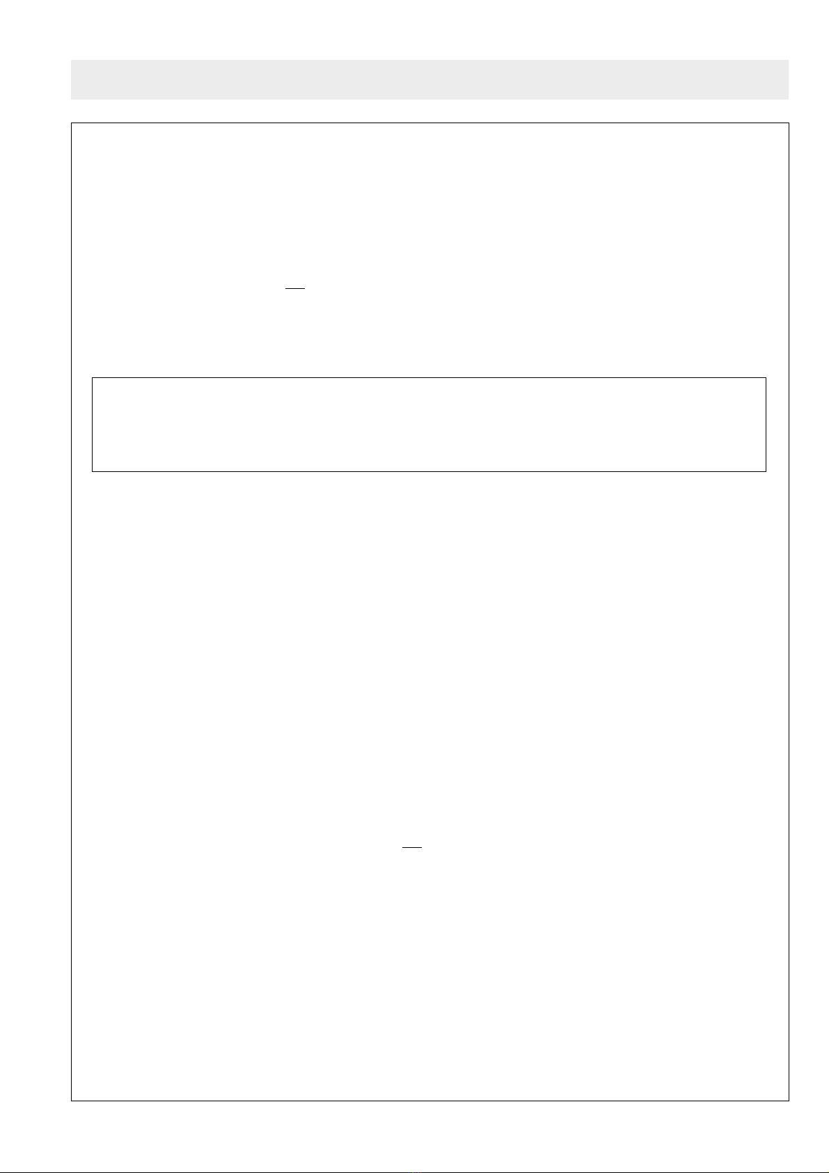
Sharp R771M-006 User manual

1
771M -
WARNING TO SERVICE PERSONNEL
Microwave ovens contain circuitry capable of producing very high voltage and current. Contact with following
parts will result in electrocution:-
High voltage capacitor, High voltage transformer, Magnetron, High voltage rectifier assembly, High voltage
harness.
REMEMBER TO CHECK 3D
1) Disconnect the supply.
2) Door opened, and wedged open.
3) Discharge high voltage capacitor.
WARNING AGAINST THE CHARGE OF THE HIGH-VOLTAGE CAPACITOR
The high-voltage capacitor remains charged about 60 seconds after the oven has been switched off. Wait for
60 seconds and then short-circuit the connection of the high-voltage capacitor (that is, of the connecting lead
of the high-voltage rectifier) against the chassis using a screwdriver with an insulated handle.
Sharp recommend that wherever possible, fault-finding is carried out with the supply disconnected.
In some cases, it may be necessary to connect the supply with the cover removed to carry out fault
investigation in the control circuitry. In such cases, the high voltage circuit should be disabled as
described below to reduce the hazards:-
• Carry out 3D checks (see above).
• Disconnect the supply leads from the high voltage transformer, making a note of the polarity. Insulate the
connectors, ensuring they are positioned away from the transformer and fastened there.
• Connect any relevant test equipment e.g. voltmeter.
• Reconnect the oven to the supply, then close the door.
• Note the results of the test, taking care to keep clear of the operational oven.
• Carry out 3D checks (see above).
• Reconnect the leads to the transformer. Take care to observe correct polarity.
• Carry out 4R checks (see below).
Microwave ovens should not be used without a load. To test for the presence of microwave energy within
a cavity, place a cup of cold water on the oven turntable, close the door and set the microwave timer for one
(1) minute, set the power level to HIGH (100%) and push the start key. When the one (1) minute has elapsed
(timer at zero) carefully check that the water is now hot.
AFTER REPAIR REMEMBER TO CHECK 4R
1) Reconnect all leads removed from components during testing.
2) Replace the outer case (cabinet).
3) Reconnect the supply.
4) Run the oven. Check all functions.
When all service work is completed, and the oven is fully assembled, the microwave power output should
be checked and microwave leakage test carried out.
IMPORTANT: If the oven becomes inoperative because of a blown fuse F8A in the 1st latch switch -
monitor switch circuit, check the 1st latch switch and monitor switch before replacing the fuse F8A.
WARNING

2
771M -
CAUTION/WARNING
CAUTION
MICROWAVE RADIATION
Serviceengineersshouldnotbeexposedtothemicrowave
energy which may radiate from the magnetron or other
microwave generating devices if it is improperly used or
connected. All input and output microwave connections,
waveguides,flanges and gasketsmust be secured.Never
operate the device without a microwave energy absorbing
load attached. Never look into an open waveguide or
antenna while the device is energized.
WARNING
Servicing and repair work must be carried out only by
trained service engineers.
All the parts marked "*" on parts list are used at voltages
more than 250V.
Removal of the outer wrap gives access to potentials
above 250V.
All the parts marked "∆" on parts list may cause undue
microwave exposure, by themselves, or when they are
damaged, loosened or removed.
SPECIFICATION
ITEM DESCRIPTION
Power Requirements 230-240 Volts
50 Hertz
Single phase, 3 wire earthed
Power Consumption Microwave cooking 1.6 kW Approx. 7 A
Top Grill mode 1.25 kW Approx. 5.2 A
Grill cooking Bottom Heater mode 0.85 kW Approx. 3.5 A
Top and Bottom mode 2.05 kW Approx. 8.5 A
Dual cooking Micro and Top Grill 2.8 kW 12A Approx.
Micro and Bottom Heater 2.3 kW 10A Approx.
Power Output
900 W nominal of RF microwave energy (measured by method of IEC 705)
Operating fequency 2450 MHz
Grill heating element Power Output (Top Grill)
1200 W (600 W x 2)
Bottom heating element Power Output
800W
Case Dimensions Width 520 mm
Height 309 mm including foot
Depth 436 mm
Cooking Cavity Dimensions Width 349 mm
Height 207 mm
Depth 357 mm
Turntable diameter 325 mm
Control Complement Jog Touch Control System
Clock (1:00 - 12:59) / Timer (0 - 90 minutes)
Microwave Power for Variable Cooking
Repetition Rate;
100% ...................................... Full power throughout the cooking time
70% ........................................................ approx. 70% of FULL Power
50% ........................................................ approx. 50% of FULL Power
30% ........................................................ approx. 30% of FULL Power
10% ........................................................ approx. 10% of FULL Power
FUNCTION KEYS:
LESS ( )/MORE ( ) keys, WEIGHT CONVERSION key
TIMER key, PIZZA key, BREAKFAST key,
AUTO COOK key, AUTO DEFROST key, MICROWAVE POWER LEVEL key
DUAL key, GRILL key, OVEN key, STOP / CLEAR key,
AUTO MINUTE / START key, CLOCK key, TIME/WEIGHT knob
Set Weight Approx. 19 kg
WARNING
THIS APPLIANCE MUST BE EARTHED. THE WIRES IN THIS MAINS LEAD ARE COLOURED IN
ACCORDANCE WITH THE FOLLOWING CODE:
GREEN-AND-YELLOW : EARTH BLUE : NEUTRAL BROWN : LIVE
If the mains lead is replaced, only part number QACCBA004URE1 should be used.
PRODUCT DESCRIPTION

3
771M -
OVEN
1. Control panel
2. Oven lamp
3. Grill heating element (Top Grill)
4. Door opening button
5. Waveguide cover
6. Oven cavity
7. Turntable motor shaft
8. Grill heating element
(Bottom Heater)
9. Door seals and sealing surfaces
10.Ventilation openings
11.Outer cabinet
12.Power supply cord
R-771
SNACK AUTO
COOK
E
I
NL
GB D
F
WATT
+
1
min
/KG
...
.
.
.
STOP
1
4
10 11
12
567
2
3
8
910
TurntableTurntable
support
High rack
Low rack
Turntable
motor shaft
Bottom
heater
1. Ensure that the bottom heater is in the lowest
position as shown the figure. As it is possible to
move it up and down to help with cleaning.
2. Place the turntable support over the turntable
motor shaft on the floor of the cavity.
3. Then place the turntable on to the turntable sup-
port.
10 11
12
WARNING: Before carrying out any work carry out 3D checks
1) Disconnect the supply.
2) Door opened, and wedged open.
3) Discharge high voltage capacitor.
RE-WIRING
Ensure the following:
1. Wires must not touch:
a) High voltage parts.
(Magnetron, high voltage transformer, high voltage capacitor and high voltage rectifier assembly)
b) Parts that become hot.
(Heating elements, oven lamp, oven cavity magnetron and high voltage transformer)
c) Sharp edges.
(Bottom plates, oven cavity, waveguide flange, chassis support and other metallic parts)
d) Movable parts.
(Fan blade, any motor, switch, switch lever and open button)
2. Positive lock connectors are fitted correctly. Ensure the locking pin is located correctly.
3. Wires are connected correctly as per pictorial diagram.
4. No wire leads are trapped by the outer wrap.
WIRING / RE-WIRING
APPEARANCE VIEW

4
771M -
MICROWAVE COOKING CONDITION
100% (HIGH) COOKING
70% (MEDIUM HIGH), 50% (MEDIUM),
30% (MEDIUM LOW), 10% (LOW COOKING)
The following levels of microwave power are given.
SETTING
100%
32 sec. ON
Approx. 100%
70%
24 sec. ON 8 sec. OFF
Approx. 70%
50%
18 sec. ON 14 sec. OFF
Approx. 50%
30%
12 sec. ON 20 sec. OFF
Approx. 30%
10%
6 sec. ON 26 sec. OFF
Approx. 10%
Note: The On/Off time ratio does not exactly correspond
to the percentage of microwave power, because
approx. 3 seconds are needed for heating up the
magnetron filament.
DUAL COOKING CONDITION
Power level ON time OFF time
100% 48 sec. 0 sec.
70% 36 sec. 12 sec
50% 26 sec. 22 sec.
30% 16 sec. 32 sec
10% 8 sec. 40 sec
Power level 0% can not be programmed in Dual Cooking
condition.
LIMITATIONS OF POWER OUTPUT IN MANUAL
OPERATION
After the same cooking mode is carried out for more than
the specified cooking time, the power output is automati-
cally reduced by turning the control relays on and off
intermittently, as shown in the table below. This is to
protect the oven door against temperature rising.
Specified cooking Limited power Time base
Cooking mode time (minutes) output (%) (seconds)
Microwave 20 70 32
Top grill 30 50 48
Bottom heater 45 50 48
Top grill and Bottom
15 (Top) 50 48
heater or Oven cooking
15 (Bottom) 50 48
Micro. + Top 20 (Micro.) 70 48
grill heater 15 (Grill) 50 48
Microwave + 20 (Micro.) 70 48
bottom heater 15 (Heater) 50 48
NOTE:
1. In case of Automatic operations, the limitations of
power output are not carried out.
2. In case that the stop key is pressed or the oven door is
opened during cooking, the limitations of power output
are carried out after the total cooking time beyond the
specified cooking time.
3. In case of the two or more same cooking modes are
carried out, the limitations of power output are carried
out after the total cooking time beyond the specified
cooking time.
4. In case of the two or more different cooking modes are
carried out, the specified cooking time is started to
countfromthepointwhenthecookingmodeischanged.
5. If the cooking mode has the power level display, the
power level is also displayed when the limitations of
power output are carried out.
OPERATION SEQUENCE
D
U
A
L

5
771M -
DOOR OPEN MECHANISM
DOOR LATCH HOOK
MONITOR SWITCH
MONITORED
LATCH SWITCH
STOP SWITCH
OPEN LEVER
LATCH
HEADS
Figure D-1. Door Open Mechanism
FIRE SENSING FEATURE
This model incorporates a sensing feature which will stop
the oven's operation if there is a fire in the oven cavity
during microwave cooking.
This accomplished by the LSI repeatedly measures the
voltageacrossthe temperature measurement circuit (ther-
mistor) during it's 32-seconds time base comparing the
obtained voltage measurements. If the most recent volt-
age measured is 300mV grater than the previous voltage
measured, the LSI judges it as a fire in the oven cavity and
switches off the relays to the high voltage transformer and
fan motor. The LSI also stops counting down. Please refer
to the following section for a more detailed description.
Operation
Please refer to the timing diagrams below.
1. Thethermistor operates within a32-seconds time base
and it is energized for three (3) seconds and off for 29
seconds. Two (2) seconds after the thermistor is
energized, the voltage across the temperature meas-
urement circuit is sampled by the LSI.
2. The above procedure is repeated. If the difference
between the first voltage measured (in step 1) and the
voltage measured when the procedure is repeated
(step 2) is greater than 300mV the LSI makes the
judgment that there is a fire in the oven cavity and will
switch off the relays to the high voltage transformer and
fan motor. The LSI also stops counting down.
CAUTION: BEFORE REPLACING A BLOWN FUSE
F8A TEST THE MONITORED LATCH
SWITCH, MONITOR SWITCH AND
MONITOR RESISTOR FOR PROPER
OPERATION.
When troubleshooting the microwave oven, it is helpful to
followtheSequenceofOperationinperformingthechecks.
Many of the possible causes of trouble will require that a
specific test be performed. These tests are given a proce-
dure letter which will be found in the “Test Procedure”
section.
TROUBLESHOOTING GUIDE
IMPORTANT: If the oven becomes inoperative because
of a blown fuse F8A in the primary latch
switch - monitor switch circuit, check the
primary latch switch, monitor switch and
monitor resistor before replacing the fuse
F8A.
3. Once the fire sensor feature has shut the unit down, the
programmed cooking cycle may be resumed by press-
ing the "START" pad or the unit may be reset by
pressing the "CLEAR" pad.
THERMISTOR
SENSING
VOLTAGE
ON
OFF
ON
OFF
0 29 64 (sec.)
3 sec.
Sensing the voltage across temperature mesure circuit.
OPEN JUDGE BY THERMISTOR
1. If the temperature of the thermistor does not rise to
more than 40˚C after 4 minutes and 15 seconds from
when the oven is started in convection, grill or dual
cooking (Microwave and Convection) mode, the oven
is turned off.
2. When the thermistor or the wire harness to the thermis-
tor is opened, the oven is turned off after 4 minutes and
15 seconds because this condition is same as above.
MONITORED
FUNCTION OF IMPORTANT COMPONENTS

6
771M -
MICROWAVE OUTPUT POWER (IEC-705)
The power output of this oven is rated using the method specified by IEC-705. Full details of how to carry out this
procedure can be found in the Sharp Technical Training notes which is available from Sharp Parts Centre
(part number SERV-LITMW01).
The IEC-705 procedure must be carried out using laboratory-type procedures and equipment. These require-
ments make the procedure unsuitable for routine performance checks.
Note: The following test method gives an indication of the output power only, it cannot be used to establish the
actual/ rated output power. If the true output power is required, then the IEC-705 test method must be used.
Alternative simplified method:
1. Place 2 litres of cold water (between 12°C and 20°C) in a suitable container.
2. Stir the water and measure the temperature in °C. Note temperature as T1.
3. Place the container in the microwave and heat the water for 2 minutes on full power.
4. When the 2 minutes is completed, remove the container and stir the water. Note the water temperature as T2.
5. Calculate the output power using the following formula:
R.F. Power Output = (T2 - T1) x 80.
MICROWAVE LEAKAGE TEST
This oven should be tested for microwave leakage on completion of any repair or adjustment, following the
procedure described in the Sharp Technical Training notes (part number SERV-LITMW01). The maximum
leakage permitted in BS EN 60335-2-25 is 50W/m2 (equivalent to 5mW/cm2), however it is not normal to detect
any significant leakage, therefore, any leakage which is detected should be investigated.
It is essential that only leakage detectors with current calibration traceable to the National Physical Laboratories
are used.
Suitable leakage detectors : CELTEC A100
APOLLO X1
OUTPUT POWER TEST PROCEDURE

7
771M -
TEST PROCEDURES
PROCEDURE
LETTER
ATOUCH CONTROL PANEL ASSEMBLY TEST
COMPONENT TEST
The touch control panel consists of circuits including semiconductors such as LSI, ICs, etc. Therefore,
unlike conventional microwave ovens, proper maintenance can not be performed with only a
voltmeter and ohmmeter.
In this service manual, the touch control panel assembly is divided into two units, Control Unit and Key
Unit, and troubleshooting by replacement is described according to the symptoms indicated.
1. Key Unit Note : Check key unit ribbon connection before replacement.
The following symptoms indicate a defective key unit. Replace the key unit.
a) When touching the pads, a certain pad produces no signal at all.
b) When touching a number pad, two figures or more are displayed.
c) When touching the pads, sometimes a pad produces no signal.
2. Control Panel
The following symptoms indicate a defective control unit. Before replacing the control unit.
perform the key unit test (Procedure N) to determine if control unit is faulty.
2-1 In connection with pads
a) When touching the pads, a certain group of pads do not produce a signal.
b) When touching the pads, no pads produce a signal.
2-2 In connection with indicators
a) At a certain digit, all or some segments do not light up.
b) At a certain digit, brightness is low.
c) Only one indicator does not light up.
d) The corresponding segments of all digits do not light up; or they continue to light up.
e) Wrong figure appears.
f) A certain group of indicators do not light up.
g) The figure of all digits flicker.
2-3 Other possible troubles caused by defective control unit.
a) Buzzer does not sound or continues to sound.
b) Clock does not operate properly.
c) Cooking is not possible.
d) Proper temperature measurement is not obtainned.
CARRY OUT 4R CHECKS.
BKEY UNIT TEST
If the display fails to clear when the STOP/CLEAR pad is depressed, first verify the flat ribbon
cable is marking good contact, verify that the door sensing switch (stop switch) operates properly;
that is the contacts are closed when the door is closed and open when the door is open. If the
door sensing switch (stop switch) is good, disconnecct the flat ribbon cable that connects the key
unit to the control unit and make sure the door sensing switch is closed (either close the door or
short the door sensing switch connecter). Use the Key unit matrix indicated on the control panel
schematic and place a jumper wire between the pins that correspond to the STOP/CLEAR pad
marking momentary contact. If the control unit responds by clearing with a beep the key unit is
faulty and must be replaced. If the control unit does not respond, it is a faulty and must be
replaced. If a specific pad does not respond, the above method may be used (after clearing the
control unit) to determine if the control unit or key pad is at fault.
G11
G7
G5,9
G2
G4,12
G10 G6
G3,8
G1
KEY UNIT
PIZZA
GRILL
DUAL
GRILL
AUTO
COOK
OVEN
(C˚)
STOP/
CLEAR
AUTO
START/
CLOCK
START/
AUTO
MINUTE
BREAKFAST
AUTO
DEFROST
MICROW.
POWER
LEVEL
TIMER
Kg / Lb

8
771M -
TEST PROCEDURES
PROCEDURE
LETTER COMPONENT TEST
CRELAY TEST
CARRY OUT 3D CHECKS.
Remove the outer case and check voltage between Pin Nos. 1 and 3 of the 4 pin connector (A) on
the control unit with an A.C. voltmeter.
The meter should indicate 230-240 volts, if not check oven circuit.
Relay Test
Check voltage at the relay coil with a D.C. voltmeter during the microwave cooking operation.
convection cooking operation or grill operation.
DC. voltage indicated .......... Defective relay.
DC. voltage not indicated .... Check diode which is connected to the relay coil. If diode is good,
control unit is defective.
RELAY SYMBOL OPERATIONAL VOLTAGE CONNECTED COMPONENTS
RY1 Approx. 24.0V D.C. Oven lamp / Turntable motor
RY2 Approx. 18.0V D.C. High voltage transformer
RY3 Approx. 18.0V D.C. Grill heating element (Top grill)
RY4 Approx. 18.0V D.C. Bottom heating element
RY5 Approx. 24.0V D.C. Fan motor
CARRY OUT 4R CHECKS.
To protect the electronic circuits, this model is provided with a fine foil pattern added to the input circuit
on the PWB, this foil pattern acts as a fuse. If the foil pattern is open, follow the troubleshooting guide
given below for repair.
Problem: POWER ON, indicator does not light up.
CARRY OUT 3D CHECKS.
STEPS OCCURANCE CAUSE OR CORRECTION
1 The rated AC voltage is not present at Check supply voltage and oven power cord.
Power terminal of CPU connector (CN-A).
2 The rated AC voltage is present at primary Low voltage transformer or secondary circuit defective.
side of low voltage transformer. Check and repair.
3 Only pattern at "a" is broken. *Insert jumper wire J1 and solder.
(CARRY OUT 3D CHECKS BEFORE REPAIR)
4 Pattern at "a" and "b" are broken. *Insert the coil RCILF2003YAZZ between "c" and "d".
(CARRY OUT 3D CHECKS BEFORE REPAIR)
D PROCEDURES TO BE TAKEN WHEN THE FOIL PATTERN ON THE PRINTED WIRING
BOARD (PWB) IS OPEN.
NOTE: *At the time of these repairs, make a
visualinspectionofthevaristorforburn-
ing damage and examine the trans-
former with tester for the presence of
layer short circuit (check primary coil
resistance).
If any abnormal condition is detected,
replace the defective parts.
CARRY OUT 4R CHECKS.
(J1)
a
c
b
d
CN -A
RY1
D21
T1
VRS1
1

9
771M -
TOUCH CONTROL PANEL ASSEMBLY
OUTLINE OF TOUCH CONTROL PANEL
4) ACL
A circuit to generate a signals which resets the LSI to
the initial state when power is supplied.
5) Buzzer Circuit
The buzzer is responsive to signals from the LSI to emit
audible sounds (key touch sound and completion
sound).
6) Door Sensing Switch (Stop Switch)
A switch to "tell" the LSI if the door is open or closed.
7) Relay Circuit
To drive the magnetron, heating element, fan motor,
turntable motor and light the oven lamp.
8) Encoder
The encoder converts the signal generated by LSI into
the pulse signal, and the pulse signal is returned to the
LSI.
9) Back Light Circuit
A circuit to drive the back light (Light emitting diodes
LD1 - LD5).
10) Indicator Circuit
This circuit consists of 4-digits, 30-segments and 3-
common electrodes using a Liquid Crystal Display.
11) Temperature Measurement Circuit
The temperature in the oven cavity is sensed by the
thermistor.
The variation of resistance according to sensed tem-
perature is detected by the temperature measurement
circuit and the result applied to LSI.
The result of detecting is given to LSI controlling the
relay and display.
The touch control section consists of the following units as
shown in the touch control panel circuit.
(1) Key Unit
(2) Control Unit
The principal functions of these units and signals commu-
nicated among them are explained below.
Key Unit
The key unit is composed of a matrix, signals generated in
the LSI are sent to the key unit through P23 - P27.
When a key pad is touched, a signal is completed through
the key unit and passed back to the LSI through P74 - P77
to perform the function that was requested.
Control Unit
Control unit consists of LSI, power source circuit, synchro-
nizing signal circuit, ACL circuit, buzzer circuit, tempera-
ture measurement circuit, indicator circuit, encoder circuit,
and back light circuit.
1) LSI
This LSI controls the temperature measurement sig-
nal, the key strobe signal, relay driving signal for oven
function and indicator signal.
2) Power Source Circuit
This circuit generates voltage necessary in the control
unit.
Symbol Voltage Application
VC -5.2V LSI(IC1)
3) Synchronizing Signal Circuit
The power source synchronizing signal is available in
order to compose a basic standard time in the clock
circuit. It accompanies a very small error because it
works on commercial frequency.

10
771M -
TOUCH CONTROL / DESCRIPTION OF LSI
LSI(IZA929DR)
The I/O signal of the LSI(IZA929DR) are detailed in the following table.
Pin No. Signal I/O Description
ON
OFF
During cooking, or for 5 minutes or more
after
g
rill cookin
g
or dual cookin
g
L
GND
H.
A
B
C
H: GND
L
0.12 sec
2.4 sec
1.2 sec 1.2 sec
20 msec
During cooking
H
L
ON
OFF
During
cooking
L
GND
H.
(Grill or dual)
ON
OFF
During
cooking
L
GND
H.
(Grill or dual)
ON/OFF time ratio in Mi-
cro cooking
(a. 32second time base)
ON/OFF time ratio in Mi-
cro cooking
(a. 48second time base)
MICRO ON OFF
COOK
100% 32sec. 0sec.
70% 24sec. 8sec.
50% 18sec. 14sec.
30% 12sec. 20sec.
10% 6sec. 26sec.
MICRO ON OFF
COOK
100% 48sec. 0sec.
70% 36sec. 12sec.
50% 26sec. 22sec.
30% 16sec. 32sec.
10% 8sec. 40sec.
1 C1 IN Terminal not used.
2 VL1 IN Power source voltage input terminal.
Standard voltage for LCD.
3-6 AN7-AN4 IN Terminal to change cooking constant.
7 AN3 IN Terminal not used.
8 AN2 IN Input signal which communicates the door open/close information to LSI.
Door closed; "H" level signal.
Door opened; "L" level signal.
9 AN1 IN Terminal not used.
10 AN0 IN Temperature measurement input: OVEN THERMISTOR.
By inputting DC voltage corresponding to the temperature detected by the
thermistor, this input is converted temperature by the A/D converter built into the
LSI.
11-12 P57-P56 OUT Timing signal output terminal for temperature measurement (OVEN).
"L" level (-5V) : Temperature measuring timing. (Oven cooking)
"H" level (GND) : Thermistor open timing.
13 P55 OUT Fan motor driving signal.
To turn on and off the fan motor relay
RY5. "L" level during cooking, or for 5
minutes or more after grill cooking or
dual cooking. "H" level otherwise.
14 CNTR0 OUT Signal to sound buzzer.
A: key touch sound.
B: Completion sound.
C:Whenthetemperatureof the oven cavity
reaches the preset temperature in the
preheating mode, or when the
preheating hold time (30 minutes) is
elapsed.
15 P53 OUT Oven lamp and turntable motor driving signal(Square Waveform : 50Hz).
To turn on and off shut-off relay (RY1). The
square waveform voltage is delivered to
the relay (RY1) driving circuit and relays
(RY2,RY3,RY4) control circuit.
16 P52 OUT Bottom heating element driving signal.
To turn on and off the bottom element relay
(RY4). "L" level during grill (BOTTOM
HEATER,TOP AND BOTTOM) cookingor
dual (Dual 2) cooking; "H" level otherwise.
17 P51 OUT Grill heating element (TOP GRILL) driving signal.
To turn on and off the grill heating element
relay (RY3). "L" level during grill (TOP
GRILL, TOP AND BOTTOM) cooking or
dual (Dual 1) cooking; "H" level otherwise.
18 P50 OUT Magnetron high-voltage circuit driving signal.
To turn on and off the cook
relay (RY2). In 100% POWER
operation, the signals hold "L"
level during microwave cooking
and "H" level while not
cooking. In other cooking
modes (70%, 50%, 30%, 10%)
the signal turns to "H" level and
"L" level in repetition
according to the power level.

11
771M -
TOUCH CONTROL / DESCRIPTION OF LSI
Pin No. Signal I/O Description
20 msec
H : GND
L (-5V)
19-20 P47-P46 IN/OUT Terminal not used.
21 P45 OUT Back light driving signal.
To change the brightness of the back light (Light emitting diodes LD1 - LD5). The
square waveform voltage is delivered to the back light driving circuit.
22 P44 IN/OUT Terminal not used.
23 INT1 IN Signal coming from encoder.
When the encoder is turned, the contacts of encoder make pluse signals. And
pulse signals are input into INT1.
24 INT0 IN Signal to synchronized LSI with commercial power source
frequency(50Hz).
This is basic timing for time processing of LSI.
25 P41 IN Signal coming from encoder.
Signal similar to INT1. Pulse signals are input into P41.
26 P40 IN/OUT Terminal not used.
27 P77 IN Signal coming from touch key.
When any one of G11 line keys on key matrix is touched, a corresponding signal
from P23 - P27 will be input into P77. When no key is touched, the signal is held
at "L" level.
28 P76 IN Signal similar to P77.
When any one of G7 line keys on key matrix is touched, a corresponding signal will
be input into P76.
29 P75 IN Signal similar to P77.
When any one of G5 and G9 line keys on key matrix is touched, a corresponding
signal will be input into P75.
30 P74 IN Signal similar to P77.
When any one of G2 line keys on key matrix is touched, a corresponding signal will
be input into P74.
31-33 P73-P71 IN/OUT Terminal not used.
34 P70 IN Connected to VC.
35 RESET IN Auto clear terminal.
Signal is input to reset the LSI to the initial state when power is applied. Temporarily
set to "L" level the moment power is applied, at this time the LSI is reset. Thereafter
set at "H" level.
36 XCIN IN Terminal not used.
37 XCOUT OUT Terminal not used.
38 XIN IN Internal clock oscillation frequency input setting.
The internal clock frequency is set by inserting the ceramic filter oscillation circuit
with respect to XIN terminal.
39 XOUT OUT Internal clock oscillation frequency control output.
Output to control oscillation input of XOUT.
40 VSS IN Power source voltage: -5V.
VC voltage of power source circuit input.
41 P27 OUT Key strobe signal.
Signal applied to touch-key section. A pulse signal is input to P74 - P77 terminal
while one of G4 and G12 line keys on matrix is touched.
42 P26 OUT Key strobe signal.
Signal applied to touch-key section. A pulse signal is input to P74 - P77 terminal
while one of G10 line keys on matrix is touched.
43 P25 OUT Key strobe signal.
Signal applied to touch-key section. A pulse signal is input to P74 - P77 terminal
while one of G6 line keys on matrix is touched.

12
771M -
TOUCH CONTROL / DESCRIPTION OF LSI
Pin No. Signal I/O Description
44 P24 OUT Key strobe signal.
Signal applied to touch-key section. A pulse signal is input to P74 - P77
terminal while one of G3 and G8 line keys on matrix is touched.
45 P23 OUT Key strobe signal.
Signal applied to touch-key section. A pulse signal is input to P74 - P77 terminal
while one of G1 line keys on matrix is touched.
46-48 P22-P20 IN/OUT Terminal not used.
49-50 P17-P16 IN/OUT Terminal not used.
51 SEG39 OUT Terminal not used.
60 SEG30
61 SEG29 OUT Segment data signal.
Connected to LCD.
90 SEG 0 The relation between signals are as follows:
LSI signal (Pin No.) LCD (Pin No.) LSI signal (Pin No.) LCD (Pin No.)
SEG 0 (90) ................................ 1 SEG15 (75)...........................29
SEG 1 (89) ................................ 2 SEG16 (74)...........................28
SEG 2 (88) ................................ 3 SEG17 (73)...........................27
SEG 3 (87) ................................ 4 SEG18 (72)...........................26
SEG 4 (86) ................................ 5 SEG19 (71)...........................25
SEG 5 (85) ................................ 6 SEG20 (70)...........................24
SEG 6 (84) ................................ 7 SEG21 (69)...........................11
SEG 7 (83) ................................ 8 SEG22 (68)...........................23
SEG 8 (82) ................................ 9 SEG23 (67)...........................22
SEG 9 (81) .............................. 10 SEG24 (66)...........................12
SEG10 (80) ............................. 34 SEG25 (65)...........................13
SEG11 (79) ............................. 33 SEG26 (64)...........................14
SEG12 (78) ............................. 32 SEG27 (63)...........................15
SEG13 (77) ............................. 31 SEG28 (62)...........................16
SEG14 (76) ............................. 30 SEG29 (61)...........................17
91 VCC IN Connected to GND.
92 VREF IN Connected to GND.
93 AVSS IN Connected to VC.
94 COM3 OUT Common data signal: COM3.
Connected to LCD (Pin No. 21).
95 COM2 OUT Common data signal: COM2.
Connected to LCD (Pin No. 20).
96 COM1 OUT Common data signal: COM1.
Connected to LCD (Pin No. 19).
97 COM0 OUT Common data signal: COM0.
Connected to LCD (Pin No. 18).
98-99 VL3-VL2 IN Power source voltage input terminal.
Standard voltage for LCD.
100 C2 IN Terminal not used.

13
771M -
TOUCH CONTROL
SERVICING
controls (sensor-related ones included) of the
touch control panel while keeping it connected
to the oven.
B. On some models, the power supply cord be-
tween the touch control panel and the oven
proper is so long enough that they may be
separated from each other. For those models,
therefore, it is possible to check and repair the
controls of the touch control panel while keeping
it apart from the oven proper; in this case you
must short both ends of the door sensing switch
(on PWB) of the touch control panel with a
jumper, which brings about an operational state
that is equivalent to the oven door being closed.
As for the sensor-related controls of the touch
control panel, checking them is possible if the
dummy resistor(s) with resistance equal to that
of the controls are used.
(2) Servicing the touch control panel with power
supply from an external power source:
Disconnect the touch control panel completely from
the oven proper, and short both ends of the door
sensing switch (on PWB) of the touch control panel,
which brings about an operational state that is
equivalent to the oven door being closed. Connect
an external power source to the power input termi-
nal of the touch control panel, then it is possible to
check and repair the controls of the touch control
panel; it is also possible to check the sensor-related
controls of the touch control panel by using the
dummy resistor(s).
4. Servicing Tools
Tools required to service the touch control panel as-
sembly.
1) Soldering iron: 30W
(It is recommended to use a soldering iron with a
grounding terminal.)
2) Oscilloscope: Single beam, frequency range: DC -
10MHz type or more advanced model.
3) Others: Hand tools
5. Other Precautions
1) Before turning on the power source of the control
unit, remove the aluminium foil applied for prevent-
ing static electricity.
2) Connect the connector of the key unit to the control
unit being sure that the lead wires are not twisted.
3) After aluminium foil is removed, be careful that
abnormal voltage due to static electricity etc. is not
applied to the input or output terminals.
4) Attach connectors, electrolytic capacitors, etc. to
PWB, making sure that all connections are tight.
5) Be sure to use specified components where high
precision is required.
ECB
ECB
Transistor
2SB1238
Transistor
2SA933S
KRA101M
KRC243M
1. Precautions for Handling Electronic Components
This unit uses CMOS LSI in the integral part of the
circuits. When handling these parts, the following pre-
cautions should be strictly followed. CMOS LSI have
extremely high impedance at its input and output
terminals. For this reason, it is easily influenced by the
surrounding high voltage power source, static electric-
ity charge in clothes, etc., and sometimes it is not fully
protected by the built-in protection circuit.
In order to protect CMOS LSI.
1) When storing and transporting, thoroughly wrap
them in aluminium foil. Also wrap PW boards con-
taining them in aluminium foil.
2) When soldering, ground the technician as shown in
the figure and use grounded soldering iron and
work table.
approx. 1M ohm
2. Shapes of Electronic Components
3. Servicing of Touch Control Panel
We describe the procedures to permit servicing of the
touch control panel of the microwave oven and the
precautions you must take when doing so.
To perform the servicing, power to the touch control
panel is available either from the power line of the oven
itself or from an external power source.
(1) Servicing the touch control panel with power
supply of the oven :
CAUTION:
THE HIGH VOLTAGE TRANSFORMER OF THE
MICROWAVE OVEN IS STILL LIVE DURING
SERVICING AND PRESENTS A HAZARD .
Therefore, when checking the performance of the
touch control panel, put the outer cabinet on the
oven to avoid touching the high voltage trans-
former, or unplug the primary terminal (connector)
of the high voltage transformer to turn it off; the end
of such connector must be insulated with an insulat-
ing tape. After servicing, be sure to replace the
leads to their original locations.
A. On some models, the power supply cord be-
tween the touch control panel and the oven itself
is so short that the two can't be separated.
For those models, check and repair all the

14
771M -
If the monitored latch switch, stop switch and monitor
switch do not operate properly due to a mis-adjustment,
the following adjustment should be made.
1. CARRY OUT 3D CHECKS.
2. Loosen the two (2) screws holding the latch hook to
the oven cavity front flange.
3. With the door closed, adjust the latch hook by moving
it back and forward or up and down. In and out play
of the door allowed by the latch hook should be less
than 0.5 mm. The horizontal position of the latch
hook should be placed where the monitor switch has
activated with the door closed. The vertical position
of the latch hook should be placed where the
monitoredlatch switch and stop switch have activated
with the door closed.
4. Secure the screws with washers firmly.
5. Make sure of the monitored latch switch, stop switch
and monitor switch operation. If those switches have
not activated with the door closed, two (2) screw
holding latch hook to oven cavity front flange and
adjust the latch hook position.
After adjustment, make sure of following:
1. In and out play of door remains less than 0.5 mm when
latched position. First check latch hook position,
pushing and pulling the door toward the oven face.
The results (play of the door) should be less than
0.5mm.
MONITORED
LATCH SWITCH, STOP SWITCH AND MONITOR SWITCH ADJUSTMENT
2. The contacts (COM-NO) of the monitored latch switch
and stop switch interrupt the circuit before the door
can be opened.
3. The contacts (COM-NC) of the monitor switch close
when the door is opened.
4. Re-install outer caseandcheck for microwaveleakage
around the door with an approved microwave survey
meter.(Refer to MicrowaveMeasurement Procedure.)
DOOR LATCH HOOK
MONITOR SWITCH
MONITORED
LATCH SWITCH
STOP SWITCH
OPEN LEVER
LATCH
HEADS
Figure C-4 Latch Switches Adjustment
MONITORED
COMPONENT REPLACEMENT AND ADJUSTMENT PROCEDURE

15
771M -
right edge of the front door glass into the one (1) tab
of the door frame.
2. Re-install the glass stopper to the door frame as
follows.
1) Re-install the glass stopper to the door frame so
that the two (2) holes of the glass stopper meet the
two (2) pins of the door frame.
2) Hold the glass stopper to the door frame with the
two (2) screws.
3. Re-install the latch spring to the latch head. Re-
install the latch spring to the door frame. Re-install
latch head to door frame.
4. Re-install door panel to door frame by fitting eight
(8) tabs of door frame to eight (8) holes of door
panel.
5. Fit the door panel to the door frame with four (4)
screws.
6. Insert two (2) pins of door panel on two (2) hole of
upper and lower oven hinges.
7. Re-install choke cover to door panel.
Note: After any service to the door;
Make sure that door sensing switch and moni-
tored latch switch are operating properly.
PIN
PIN
LOWER
OVEN HINGE
UPPER
OVEN HINGE
LOWER
OVEN HINGE
CHOKE COVER
DOOR
PANEL
DOOR SUB
ASSEMBLY
Figure C-6. Door Replacement
DOOR REPLACEMENT
REMOVAL
1. CARRY OUT 3D CHECKS.
2. Push the open button and open the door slightly.
3. Insert a putty knife (thickness of about 0.5mm) into
the gap between the choke cover and door frame as
shown in Figure C-5 to free engaging parts.
4. Release choke cover from door panel.
5. Now choke cover is free.
CHOKE COVER
PUTTY KNIFE
DOOR FRAME
Figure C-5. Door Disassembly
6. Release two (2) pins of door panel from two (2) holes
of upper and lower oven hinges by lifting up.
7. Now, door sub assembly is free from oven cavity.
8. Remove the four (4) screws holding the door panel to
the door frame.
9. Release door panel from eight (8) tabs of door frame
by sliding door panel downward.
10.Now, door panel is free.
11.Slide latch head upward and remove it from door
frame, releasing latch spring from door frame and
latch head.
12.Now, latch head and latch spring are free.
13.Remove the two (2) screws holding the glass stopper
to the door frame.
14.Remove the glass stopper from the door frame.
15.Slide the front door glass leftwards and then slide
upwards to release the tabs holding it.
16.Now, the front door glass is free
RE-INSTALL
1. Re-install the front door glass to the door frame as
follows.
1) Insert the upper edge of the front door glass into the
six (6) tabs of the door frame.
2) Slide the front door glass downwards and insert the
lower edge of the front door glass into the six (6) tabs
of the door frame.
3) Slide the front door glass rightwards and insert the
COMPONENT REPLACEMENT AND ADJUSTMENT PROCEDURE

16
771M -
SCHEMATIC DIAGRAM
Figure S-1. Schematic Diagram
RED
ORG
WHT/18
NO
BLK/18
HEATER
BOTTOM
BRN/18
ORG
/18
BLU/16
/18
RED
/18
ORG
ORG
/18
TOP HEATER
COM
BLU/16
WHT
WHT/16
WIRE COLOUR CODE & SYMBOL
RED : RED WHT : WHITE
BRN : BROWN
ORG : ORANGE
BLK : BLACK
BLU : BLUE
GRY : GREY
GRN : GREEN
HV : HIGH VOLTAGE WIRE
/16 : WIRE THICKNESS = AWG16
/18 : WIRE THICKNESS = AWG18
NO INDICATION SHOWS WIRE THICKNESS = AWG22
WHT
GRY
GRY
WHT/16
WHT/18
BRN/18
BLK
WHT/18
RED/18
BRN
NC
SWITCH
MONITOR
CUT-OUT
THERMAL
MG
FILTER
NOISE
F8A
FUSE
RY4
COM
N.O
FUSE 15A
EARTH
BLU BRN
NEUTRAL LIVE
NOISE SUPPRESSION COIL
/15 /15
G-Y/15
NL
10M/0.5W
4700p/250V 4700p/250V
680K/0.5W
1.16 F
AC2100V
CAPACITOR
H.V. RECTIFIER
RECTIFIER
ASYMMETRIC
TRANSFORMER
POWER
MAGNETRON
TURNTABLE
MOTOR TMT
FAN
MOTOR
FM
1ST
LATCH
CUT-OUT
THERMAL
OVEN
OL
OVEN LAMP
UNIT
CONTROL
N.O
COM
N.O
COM
B2
B1
RY2RY3
RY1
A3
RY5
A7
A5
A1
SWITCH
DOOR
B3
B4
STOR
THERMI-
0.22 /250V
*
*
*
*
*
*
INDICATES PARTS WITH POTENTIALS OVER 250V
230-240V 50Hz

17
771M -
Figure S-2. Control Panel Circuit
WIRING DIAGRAM
+
–
+
–
+
–
+
–
A1
VRS1
a
48
R1 510 1w
R50 4.7k
R51 4.7k
IC1 IZA929DR
C50
C51
R52 100k
R53 100k
SW1
DOOR SWITCH THERMISTOR
CONTROL UNIT
KEY UNIT
LIQUID CRYSTAL DISPLAY
C30 C80
R31 4.7k
R83 15k
R2 510 1w
R20 130 1w
R21 130 1w
Q1
2SA933S
Q4
2SB1238
Q2
KRA101M
Q20
KRA101M
Q22 KRC243M
Q21 KRA101M
Q23
KRA101M
Q40
KRA101M
Q3
2SB1238
Q24
KRA101M
AC230-240 V
50Hz
LOWER
HEATER
UPPER
HEATER
HIGH
VOLTAGE
TRANSFORMER
NOTE: IF NOT SPECIFIED 1/4w ±5%
IF NOT SPECIFIED 1SS270A
IF NOT SPECIFIED 0.01µF/16v
TURNTABLE
MOTOR
OVEN LAMP
FAN MOTOR
Q25
KRA101M
D1:S1NB10
RY5
RY1
RY4
RY3
RY2
6
1
c
d
b(J1)
(J13)
(J2)
(J4)
(J6)
(J8)
(J3)
(J5)
(J7)
(J9)
T1
10G471K
D20D21D22D23D24
ZD2
HZ20-1
D25
D30
C1 0.1µ/50v
C2 470µ/50v
C20 0.1µ/50v
C21
10µ/35v
C6 10µ/35v
C7
0.1µ/50v
C3
C4
SP40
C5
0.1µ/50v
R3 1k
R4 4.7k
R40 3.3k
R30 15k
R9 1k
R81
R82
12 kF
R60 15k
R61 15k
R62 15k
R63 15k CF1
4MHz
R64 100k
R65 100k
R66 100k
R67 100k
R68 15k
R69 15k
R70 15k
R10 16
WH-A
D2 D3
R71 15k
R72 15k R11 3.3k
LD1 LD2 LD3 LD4 LD5
R5 4.7k
R6 15k
R8 15k
18
C2
VL2
VL3
COM0
COM1
COM2
COM3
AVSS
VREF
VCC
SEG2
SEG3
SEG4
P73
P72
P71
P70
RESET
XCIN 35
40
45 85
90
95
50
XCOUT
XIN
XOUT
VSS
P27
P26
P25
P24
P23
P22
P21
P20
P17
P16
SEG5
SEG6
SEG7
SEG8
SEG9
SEG1
SEG0
SEG11
SEG10C1
VL1
AN7
AN6
AN5 5
10
15
20
25
55
60
65
70
75
80
30
AN4
AN3
AN2
AN1
AN0
P57
P56
P55
CNTRO
P53
P52
P51
P50
P47
P46
P45
P44
P41
P40
P77
P76
P75
P74
INT1
INT0
SEG12
SEG13
SEG14
SEG15
SEG16
SEG17
SEG18
SEG19
SEG20
SEG21
SEG22
SEG23
SEG25
SEG26
SEG27
SEG28
SEG29
SEG30
SEG31
SEG32
SEG33
SEG34
SEG35
SEG36
SEG37
SEG38
SEG39
SEG24
19
20
21
17
16
15
14
13
12
22
23
11
24
25
26
27
28
29
30
31
32
33
34
10
9
8
7
6
5
4
3
2
1
R7 15k
ZD1
HZ4C3
A3
A7
A5
NO
NO
B1
A
G11
G 2
G 6 G 1
G 7
G10
G5.9
G3.8
G4.12
BC
B2 B3 B4
NO
COM
COM
COM
( )
GRILL
OVEN
(C˚)
AUTO
COOK DUAL
GRILL
AUTO
DEFROST
STOP/
CLEAR
AUTO
START/
CLOCK
START/
AUTO
MINUTE
BREAKFAST
MICROW.
POWER
LEVEL
Kg / Lb
TIMERPIZZA
( )
( )
MICRO
AUTO COOK
K
gnfo
%
Oz
Lbs
( )

18
771M -
Figure S-3. Printed Wiring Board
0
LD1
WH-A
2
3
4
CF1 R82
R5
R3
R63
R64
R53
R52
R11
R10
R62
R81
R30
R31
R61
R60
R83
R72
R71
R70
R69
R68
D3 D2
R65
R66
R67
IC1
9
8
12
13
14
15
21
(J1)
CBA
R20
R21 Q3
BEZD2
D23
18
C50
C51
Q40
Q23
Q24
Q25
Q22
24
25
10
11
C6
C5
C30
C80
C4
R4
Q1
B
B
B
B
B
B
E
E
E
E
E
E
D30
D25
C2
ZD1
5
7
6C7
C3
C20
E
E
E
E
B
BB
B
Q2
Q21
Q4
(J8) (J9)
(J7)
(J5)
(J3)
R7
CN - G CN -A
CN - B
(J6)
(J4)
(J2)
R8 R2
R80
R40
R6
20
22
19
16 SP40
D1
C1
C21
Q20
D20
RY5 RY1
R51
R50
R9
(J12)
SW1
RY4
RY3
RY2
D21 D22
D24
T1
VRS1
R1
23
17
1
,F
LD2
17
18
1
1
4
12
1
12 4
68
7
50
30 1
100
80
34
1
LD3 LD4 LD5
WIRING DIAGRAM

19
771M -
Note: The parts marked "∆" may cause undue microwave exposure. / The parts marked "*" are used in
voltage more than 250V. / "§" Mark: Spare parts delivery section
REF. NO. PART NO. § DESCRIPTION Q'TY CODE
*
*
*
∆*
*
*
*
*∆
ELECTRIC PARTS
1- 1 QACCBA004URE1 U Power supply cord 1 AT
1- 2 FH-DZA035WRE0 U High voltage rectifier assembly 1 AP
1- 3 FPWBFA309WRE1 U Noise filter 1 AT
1- 4 FH-HZA007WRE0 J Thermistor 1 AH
1- 5 QFS-BO019MRE0 J Fuse 15A 1 AC
1- 6 QFS-CA025WRE0 J Fuse F8A 1 AB
1- 8 RC-QZA219WRE0 U High voltage capacitor 1 AT
1- 9 RTHM-A098WRE0 U Thermal cut-out 125˚C (MG.) 1 AH
1-10 RTHM-A099WRE0 J Thermal cut-out 150˚C (OVEN) 1 AH
1-11 FHET-A041WRK1 U Grill heating element asse mbly 1 BB
1-11-1 LANG-A040WRP1 U Grill heater angle 1 AC
1-11-2 PREFHA046WRP1 U Reflector 1 AR
1-11-3 QTANNA006WRE0 U Earth plate 1 AB
1-11-4 RHET-A142WRE2 U Grill heating element 2 BE
1-11-5 XBPWW30P05K00 J Screw; 3mm x 5mm 2 AA
1-12 RHET-A198WRE0 U Bottom heating element 1 AX
1-13 QSW-MA131WRE0 J Primary latch switch 1 AK
1-14 QSW-MA133WRE0 J Stop switch 1 AN
1-15 QSW-MA133WRE0 J Monitor switch 1 AN
1-16 FMOTDA056WRK0 J Turntable motor 1 AR
1-17 RMOTEA002URE0 U Fan motor 1 AW
1-18 RLMPTA066WRE0 U Oven lamp 1 AK
1-19 RTRN-A012URE0 U High voltage transformer 1 BH
1-20 RV-MZA243WRE1 U Magnetron 1 BH
CABINET PARTS
2- 1 GCABUA469WRT0 U Outer case cabinet (W) 1 AX
2- 1 GCABUA005URP0 U Outer case cabinet (G) 1 AX
2- 1 GCABUA419WRP0 U Outer case cabinet (K) 1 AX
2- 2 GDAI-A279WRP2 U Base plate 1 AV
2- 3 GLEGPA028WRE0 U Foot 2 AA
CONTROL PANEL PARTS
3- 1 DPWBFA075URU0 U Control unit 1 BP
3- 1A QCNCMA230DRE0 U 4-pin connector (CN-A) 1 AC
3- 1B QCNCMA270DRE0 U 2-pin connector (CN-B) 1 AC
3- 1C QCNCWA057DRE0 U 12-pin connector (CN-G) 1 AE
3- 1D RLCDSA055DRE0 U Liquid Crystal Display (LCD) 1 AP
3- 1E QW-QZA003URE2 U Lead wire (WH-A) 2 AB
3- 1F LHLD-A003URF1 U LCD holder 1 AC
3- 1G PSHEPA573WRE0 U LED sheet 1 AF
C1 VCKYD41HF104Z* U Capacitor 0.1 uF 50V 1 AB
C2 VCEAG51HW477M U Capacitor 470 uF 50V 1 AD
C3 VCKYD41HF104Z* U Capacitor 0.1 uF 50V 1 AB
C4-5 VCKYD41CY103N* U Capacitor 0.01 uF 16V 2 AA
C6 VCEAG31VW106M+ U Capacitor 10 uF 35V 1 AB
C7 VCKYD41HF104Z* U Capacitor 0.1 uF 50V 1 AB
C20 VCEAG31HW104M+ U Capacitor 0.1 uF 50V 1 AB
C21 VCEAG31VW106M+ U Capacitor 10 uF 35V 1 AB
C30 VCKYD41CY103N* U Capacitor 0.01 uF 16V 1 AA
C50-51 VCKYD41CY103N* U Capacitor 0.01 uF 16V 2 AA
C80 VCKYD41CY103N* U Capacitor 0.01 uF 16V 1 AA
CF1 RCRS-A012DRE0+ U Ceramic resonator (CST4.00MGW) 1 AD
D1 RSRCDA013DRE0 U Diode bridge (S1NB10) 1 AE
D2-3 VHD1SS270A/-1* U Diode (1SS270ATA) 2 AA
D20-24 VHD1SS270A/-1* U Diode (1SS270ATA) 5 AA
D25 VHD11ES1///-1* U Diode (11ES1) 1 AB
D30 VHD1SS270A/-1* U Diode (1SS270ATA) 1 AA
IC1 RH-IZA929DRE0 J LSI 1 AV
LD1-5 VHPSLZ781C9-3+ U Light emitting diode (LED) 5 AC
Q1 VS2SA933S//-3+ U Transistor (2SA933S) 1 AA
Q2 VSKRA101M//-3+ U Transistor (KRA101M) 1 AA
Q3-4 VS2SB1238//-3+ U Transistor (2SB1238) 2 AD
Q20-21 VSKRA101M//-3+ U Transistor (KRA101M) 2 AA
Q22 VSKRC243M//-3+ U Transistor (KRC243M) 1 AB
Q23-25 VSKRA101M//-3+ U Transistor (KRA101M) 3 AA
Q40 VSKRA101M//-3+ U Transistor (KRA101M) 1 AA
R1-2 VRS-B13AA511J* U Resistor 510 ohm 1W 2 AB
PARTS LIST

20
771M -
Note: The parts marked "∆" may cause undue microwave exposure. / The parts marked "*" are used in
voltage more than 250V. / "§" Mark: Spare parts delivery section
REF. NO. PART NO. § DESCRIPTION Q'TY CODE
∆∆
R3 VRD-B12EF102J* U Resistor 1.0k ohm 1/4W 1 AA
R4-5 VRD-B12EF472J* U Resistor 4.7k ohm 1/4W 2 AA
R6-8 VRD-B12EF153J* U Resistor 15k ohm 1/4W 3 AA
R9 VRD-B12EF102J* U Resistor 1.0k ohm 1/4W 1 AA
R10 VRD-B12EF160J* U Resistor 16 ohm 1/4W 1 AA
R11 VRD-B12EF332J* U Resistor 3.3k ohm 1/4W 1 AA
R20-21 VRS-B13AA131J* U Resistor 130 ohm 1W 2 AB
R30 VRD-B12EF153J* U Resistor 15k ohm 1/4W 1 AA
R31 VRD-B12EF472J* U Resistor 4.7k ohm 1/4W 1 AA
R40 VRD-B12EF332J* U Resistor 3.3k ohm 1/4W 1 AA
R50-51 VRD-B12EF472J* U Resistor 4.7k ohm 1/4W 2 AA
R52-53 VRD-B12EF104J* U Resistor 100k ohm 1/4W 2 AA
R60-63 VRD-B12EF153J* U Resistor 15k ohm 1/4W 4 AA
R64-67 VRD-B12EF104J* U Resistor 100k ohm 1/4W 4 AA
R68-72 VRD-B12EF153J* U Resistor 15k ohm 1/4W 5 AA
R82 VRN-B12EK123F* U Resistor 12k ohm ±1% 1/4W 1 AA
R83 VRD-B12EF153J* U Resistor 15k ohm 1/4W 1 AA
RY1 RRLY-A080DRE0 U Relay (OJ-SH-124LM) 1 AG
RY2 RRLY-A092DRE0 U Relay (VRB18SP) 1 AP
RY3-4 RRLY-A093DRE0 U Relay (VRB18) 2 AM
RY5 RRLY-A080DRE0 U Relay (OJ-SH-124LM) 1 AG
SP40 RALM-A014DRE0 U Buzzer (PKM22EPT-THAI) 1 AG
SW1 RVR-BA018WRE0 U Rotary encoder 1 AH
T1 RTRNPA105DRE0 U Transformer 1 AR
VRS1 RH-VZA034DRE0+ U Varistor (10G471K) 1 AD
ZD1 VHEHZ4C3///-1* U Zener diode (HZ4C-3) 1 AB
ZD2 VHEHZ201///-1* U Zener diode (HZ20-1) 1 AB
3- 2 DUNTKC028URK0 U Key unit 1 AS
3- 3 GMADIA004URF0 U Display window 1 AD
3- 4 HPNLCG003URR0 U Control panel [R-771(G)M] 1 AP
3- 4 HPNLCK004URR0 U Control panel [R-771(K)M] 1 AP
3- 4 HPNLCW013URR0 U Control panel [R-771(W)M] 1 AP
3- 5 JBTN-A024URR0 U Pizza button 1 AD
3- 6 JBTN-A017URF0 U Open button [R-771(W)M] 1 AE
3- 6 JBTN-A049URF0 U Open button [R-771(K)M] 1 AE
3- 6 JBTN-A061URF0 U Open button [R-771(G)M] 1 AE
3- 7 JKNBKA015URF0 U Rotary knob [R-771(W)M] 1 AC
3- 7 JKNBKA023URF0 U Rotary knob [R-771(K)M] 1 AC
3- 7 JKNBKA025URF0 U Rotary knob [R-771(G)M] 1 AC
3- 8 JBTN-A028URR0 U Auto/Def. button [R-771(W)M] 1 AC
3- 8 JBTN-A033URR0 U Auto/Def. button [R-771(G)M] 1 AC
3- 8 JBTN-A037URR0 U Auto/Def. button [R-771(K)M] 1 AC
3- 9 JBTN-A026URR0 U Combi food button [R-771(W)M] 1 AE
3- 9 JBTN-A031URR0 U Combi food button [R-771(G)M] 1 AE
3- 9 JBTN-A035URR0 U Combi food button [R-771(K)M] 1 AE
3- 10 JBTN-A030URF0 U Select button [R-771(W)M] 1 AD
3- 10 JBTN-A055URF0 U Select button [R-771(K)M] 1 AD
3- 10 JBTN-A067URF0 U Select button [R-771(G)M] 1 AD
3- 11 JBTN-A031URF0 U More/Less button [R-771(W)M] 1 AD
3- 11 JBTN-A057URF0 U More/Less button [R-771(K)M] 1 AD
3- 11 JBTN-A069URF0 U More/Less button [R-771(G)M] 1 AD
3- 12 JBTN-A035URF0 U Start button [R-771(W)M] 1 AB
3- 12 JBTN-A071URF0 U Start button [R-771(G)M] 1 AB
3- 12 JBTN-A079URF0 U Start button [R-771(K)M] 1 AB
3- 13 PSHEPA005URE0 U Display window film [R-771(W)M] 1 AH
3- 13 PSHEPA011URE0 U Display window film [R-771(G)M] 1 AH
3- 13 PSHEPA011URE0 U Display window film [R-771(K)M] 1 AH
3- 14 MSPRCA045WRE0 U Open button spring 1 AA
3- 15 XEPSD30P10XS0 U Screw; 3mm x 10mm 11 AA
OVEN PARTS
4- 1 DOVN-A438WRY0 U Oven cavity 1 BQ
4- 2 LBNDKA107WRP1 U Capacitor holder 1 AD
4- 3 FDUC-A309WRY0 U Air duct assembly 1 AN
4- 4 PSKR-A309WRP0 U Air separate angle 1 AE
PARTS LIST
Table of contents
Other Sharp TV manuals

Sharp
Sharp 21LF-90C User manual

Sharp
Sharp 21H1-FRU User manual

Sharp
Sharp 20N-S100S User manual

Sharp
Sharp 26SL72M User manual

Sharp
Sharp AQUOS LC-52LE640U User manual

Sharp
Sharp 21V-FS700S User manual

Sharp
Sharp 29LF-92EC User manual

Sharp
Sharp LC-43CUF8472ES User manual

Sharp
Sharp LC-32HI3012E User manual

Sharp
Sharp 20MU11 User manual

Sharp
Sharp 29F-PA330 User manual

Sharp
Sharp 27SF560 User manual

Sharp
Sharp 27U-S650 User manual

Sharp
Sharp 27SC260 User manual

Sharp
Sharp AQUOS LC-15E2E User manual

Sharp
Sharp LC-80LE960X User manual

Sharp
Sharp 66CS-03H User manual

Sharp
Sharp LC-37GP1U - 37" LCD TV User manual

Sharp
Sharp 37GQ-20FP User manual

Sharp
Sharp 21LF-90H User manual