Sharp SX76NF200 User manual

1
SX76NF200
WARNING
The chassis in this receiver is partially hot. Use an isolation transformer between the line cord plug and power
receptacle, when servicing this chassis. To prevent electric shock, do not remove cover. No user – serviceable
parts inside. Refer servicing to qualified service personnel.
SERVICE MANUAL
In the interests of user-safety (Required by safety regulations in some countries) the set should be restored
to its original condition and only parts identical to those specified should be used.
MODEL SX76NF200
SHARP CORPORATION
COLOUR TELEVISION
Chassis No. GE-3A
Page
CONTENTS
»SPECIFICATIONS .............................................2
»IMPORTANT SERVICE NOTES........................2
»ADJUSTMENT PRECAUTIONS........................3
»TROUBLE SHOOTING FLOWCHART..............9
»WAVEFORMS..................................................13
»CHASSIS LAYOUT..........................................16
»BLOCK DIAGRAM...........................................18
»DESCRIPTION OF SCHEMATIC DIAGRAM ..26
»SCHEMATIC DIAGRAM
ËCRT UNIT.....................................................27
ËMAIN UNIT ...................................................28
ËLED UNIT .....................................................35
ËKEY UNIT.....................................................35
ËPOWER UNIT ..............................................36
ËIP UNIT.........................................................38
ËCONTROL UNIT ..........................................40
Page
»PRINTED WIRING BOARD ASSEMBLIES .....42
»REPLACEMENT PARTS LIST
ËELECTRICAL PARTS
MAIN UNIT ...................................................52
POWER UNIT ..............................................57
CRT UNIT.....................................................60
IP UNIT.........................................................61
CONTROL UNIT ..........................................63
LED UNIT .....................................................63
KEY UNIT.....................................................63
ËMISCELLANEOUS PARTS..........................64
ËSUPPLIED ACCESSORIES.........................64
ËPACKING PARTS.........................................64
ËCABINET PARTS .........................................64
ËCABINET PARTS LOCATION......................64
»PACKING OF THE SET...................................65
FEATURES
ËFull Auto Channel Preset and Auto Channel Skip
Ë100 CH Program Memory
ËCATV (Hyper Band) Ready
<Used Frequency Synthesizer Tuner>
ËHigh Contrast Picture
ËTELETEXT(10 page)
ËON Timer / OFF Timer / Reminder
ËPicture in Picture / Twin Screen
ËBlue Back Noise Mute
ËWhite Temperature Adjustment
Ë100Hz SCAN / Progressive SCAN
ËHeadphone Terminal
ËStereo (NICAM / A2) Decoder
ËRotation adjustment (picture tilt adjustment)
ËComponent Input Terminal
S34Q9SX76NF20

2
2-1 2-2
SX76NF200
SPECIFICATIONS
Convergence .................................................................Self Convergence System
Focus........................................................... Electrostatic Focus High Bi-Potential
Sweep Deflection......................................................................................Magnetic
Intermediate Frequencies
Picture IF Carrier ..................................................................................38.9MHz
Sound IF Carrier Frequency
5.5MHz ..............................................................................................33.4MHz
Colour Sub-Carrier Frequency............................................................34.47MHz
Power Input ........................................................................ AC 220 ~ 240V 50 Hz
Power Consumption ......................................................................................163W
Audio Power Output Rating ............................................5W + 5W + 10W(at Max.)
Speaker
Size.............................................................................. 11 x 5 cm Elliptic (2 pcs)
10cm Round (1pc)
Voice Coil Impedance..............................................................4 ohm (11 x 5cm)
8 ohm (10cm)
Aerial Input Impedance
VHF/UHF ............................................................................ 75 ohm Unbalanced
Receiving System (PAL-B/G)
VHF.......................................................................................AU 0 thruAU 12 ch
UHF ........................................................................................ E 21 thru E 69 ch
Receiving Frequency................................................... 45.25MHz thru 855.25MHz
Dimensions................................................................................... Width: 880.0mm
Height: 566.0mm
Depth: 545.0mm
Weight(approx): 54.5 kg
Cabinet material ....................................................................................All Plastics
Specifications are subject to change without prior notice.
IMPORTANT SERVICE NOTES
Maintenance and repairing of this receiver should be done by quali-
fied service personnel only.
SERVICE OF HIGH VOLTAGE SYSTEM AND PIC-
TURE TUBE
When servicing the high voltage system, remove static charge from it by
Connecting a 10K ohm Resistor in series with an insulated wire(such as a
test probe) between picture tube dag and 2nd anode lead. (AC line cord
should be disconnected from AC outlet.)
1. Picture tube in this receiver employs integral implosion protection.
2. Replace with tube of the same type number for continued safety.
3. Do not lift picture tube by the neck.
4. Handle the picture tube only when wearing shatterproof goggles and after discharging
the high voltage completely.
X-RAY
This receiver is designed so that any X-Ray radiation is kept to an absolute
Minimum. Since certain malfunctions or servicing may produce potentially
hazardous radiation with prolonged exposure at close range, the following
precautions should be observed:
1. When repairing the circuit, be sure not to increase the high voltage to more than 34.5kV(at
beam 0
µ
A) for the set.
2. To keep the set in a normal operation , be sure to make it function on 30.5kV
±
1.5kV(at
beam 1800
µ
A) in the case of the set. The set has been factory - Adjusted to the above-
mentioned high voltage.
*If there is a possibility that the high voltage fluctuates as a result of the repairing,
never forget to check for such high voltage after the work.
3. Do not substitute a picture tube with unauthorized types and/or brands which may cause
excess X-ray radiation.
BEFORE RETURNING THE RECEIVER
Before returning the receiver to the user, perform the following safety Checks.
1. Inspect all lead dress to make certain that leads are not pinched or that hardware is not
lodged between the chassis and other metal parts in the receiver.
2. Inspect all protective devices such as non-metallic control knobs, insulating fishpapers,
cabinet backs, adjustment and compartment covers or shields, isolation resistor- ca-
pacity networks, mechanical insulators etc.

3
3-1 3-2
SX76NF200
ADJUSTMENT PRECAUTIONS
Entering service mode
(Method 1)
1. Send the service R/C code to enter the service mode.
2. Send it again to exit the service mode.
(Method 2)
1. Short the jumper to enter the service mode.
Connect "J 311" with "J 403".
2. Stop shorting the jumper to exit the service mode.
Service mode menu
1. Select item by ch up/down ,push vol up/down.
2. When you adjust geometry, please set Full mode by "Wide mode key".
3.About geometry adjustment, it is necessary to adjust 2 pattern.
»50hz interlace signal
»60hz interlace signal
About "Reset TV-set"
1. When replacing the flash ROM or EEPROM, the TV may need to be reset.
2. Unless necessary, do not reset the TV because the adjustment data will be
initialized.
3. To reset the TV, enter the "Reset TV-set" menu and press the SURROUND key.
After about 30 seconds, the NVM data will be initialized.
Changing the NVM data
1. Enter the "NVM Edit" menu.
2. Input the addr. and data in hex with the number keys or vol up/down key.
»NVM-edit addr. (hex) ----
»NVM-edit data (hex) --
MAIN (Wiring side)
Fig.1

4
4-1 4-2
SX76NF200
E1
PIF ADJUSTMENT
NO
1ADJUSTMENT POINT
RF-AGC
ADJUSTMENT
(I2C BUS CONTROL)
ADJUSTMENT CONDITION / PROCEDURE
(1) Receive "PAL COLOUR BAR" signal.
E-10cH
Signal strength: 54 ±1dBµV (50 ohm open)
(2) Call "Auto AGC" mode in service mode (Additional
Setting).
(3) Push "Vol up" or "Vol down" key, automatically adjust.
*change indication from <STOP> to <CHECK> at start
adjustment.
when adjustment is finished, <CHECK> to <STOP>
WAVEFORM OR OTHERS
Note: For the 50 ohm signal strength
gauge, when not using 50/75 impedance
adapter, signal strength is 54±1dBµV(50
ohm open), instead of 56 ±1dBµV(75 ohm
open).
precaution: The loss of using impedance
adapter.
CUT OFF, BKGD ADJUSTMENT
NO
1ADJUSTMENT POINT
AGING ADJUSTMENT CONDITION / PROCEDURE
(1) Receive PR-0ch (BLUE BACK OFF), "NOISE PICTURE"
(2) Aging 30 minutes.
WAVEFORM OR OTHERS
1 CRT CUTOFF
ADJUSTMENT
Service mode I2C bus
data adjustment
(1) Receive E-5CH (Monoscope pattern).
(2) Select P-NORM with the remote controller.
(3) Turn on the service SW, and select "Tube Measurement
(1) mode.
(4) Select the screen VR 0/10.
(5) Press "-/--" key of the remote controller to select the
horizontal centering mode.
(6) Turn the screen VR in the opposite direction to the point
where the horizontal centering raster goes out.
Note1: Apply the adjustment after aging with the beam
current 1,600 ±50mA or more for 30 min or more.
(7) Press "-/--" key of the remote controller to select the
normal mode.
2 WHITE BALANCE
BACKGROUND
(CUT OFF BKGD)
I2C bus adjustment
(1) Receive E-5CH (Monoscope pattern).
(2) Select Picture-Normal with the remote controller.
(3) Receive the window pattern with AV input.
(4) With the data of G-drive and B-drive, adjust the colour
temperature 12300°K of the center white area.
(5) Adjust the right dark area of the window to 12300°K with
G-cut off and B-cut off.
(6) Readjust the colour temperature at the white peak.
(7) Check 12300°K at the low white.
Note 1:Apply this adjustment after aging with the beam
current 1,600 ±50mA or more for 30 min or more.
(On the white or green monocolor screen)
*The colour temperature is based on the shipment initial
setting table.
* The following item is carrying out simultaneously.
No. 2, 4, 5
• 12300°K X : 0.272±0.010
Y : 0.275±0.010
(With Minolta colour thermometer CA-100)
*Before doing the adjustment, make sure the
R/G/B-cut and the R/B/G-Drive is at initial
values.
R-CUT:300 R-DRIVE:400
G-CUT:300 G-DRIVE:400
B-CUT:300 B-DRIVE:400
On the monocolor screen of white or green.

5
5-1 5-2
SX76NF200
CUT OFF, BKGD ADJUSTMENT CONTINUED
NO
3ADJUSTMENT POINT
Max Beam Check ADJUSTMENT CONDITION / PROCEDURE
(1) Receive 50Hz Monoscope Pattern Signal.
(2) Press R/C to set Picture NORMAL condition.
(3) Select full mode.
(4) Connect the DC miliammeter between TP601 and
TP602
(Full Scale: 3mA Range)
(5) Beam current must be within 1800 ±100µA.
4 SUB-CONTRAST
(SUB-CONT)
I2C bus adjustment
(RF SIGNAL)
(1) Receive the window pattern with AV input.
(2) Make the picture normal with the remote controller.
(3) Select the SUB-CONTRAST adjustment mode with the
remote controller, and adjust 50% white to 140 ±10cd.
WAVEFORM OR OTHERS
5 SUB-BRIGHTNESS
(SUB BRI)
I2C bus adjustment
(RF signal)
(1) Receive the window pattern with AV input.
(2) Make the picture normal with the remote controller.
(3) Select the sub-bright adjustment mode with the remote
controller, and adjust the right dark white area of the
window pattern to 2.0cd ±0.5cd.
Note 2: Use "Y" of Minolta colour analyzer
CA-100.
Note 3: Use the PAL window pattern of
the signal generator SX1006 for
adjustment.
* When E-2 CH (Crosshatch pattern )or
eqivalent signal is received.
1. Make the picture normal with the remote
controller.
2. Adjust the 3rd (1 thru 5 from the left) balck
of the window pattern to sink.
Note 4: window pattern
Dark white for SUB-BRIGHT
50% white for SUB-CONT
CUT OFF POINT
PAL CHROMA ADJUSTMENT
NO
1ADJUSTMENT POINT
SUB COLOUR
I2C Bus adjustment
(RF signal)
ADJUSTMENT CONDITION / PROCEDURE
(1) Receive the "PAL Colour Bar" signal. (E-10CH)
(2) Make the picture normal with the remote controller.
(3) Connect the oscilloscope to TP1802 (Use 10:1 probe)
Range:2V/Div Sweep time:20µsec/Div
(4) Set the sub colour adjustment mode with the remote
controller, and vary the sub colour data to make 75% W
of the PAL colour bar and RED at the same level for
adjustment shown in Fig. 1-1.
WAVEFORM OR OTHERS
NTSC CHROMA ADJUSTMENT
NO
1ADJUSTMENT POINT
SUB-TINT
I2C bus adjutment
(RF signal)
ADJUSTMENT CONDITION / PROCEDURE
(1) Select the sub-tint adjustment mode to receive NTSC
colour bar.
(2) Connect the oscilloscope to TP1803
Range :20mV/Div(AC) (Use Probe 10:1)
Sweep time :10µsec/Div
(3) Vary the sub tint data to adjust the waveform to be
gained as shown in Fig 1-1.
*Change NVM data
position 7F1
data 07=>00 07 is the offset value for factory.
WAVEFORM OR OTHERS
HORIZONTAL, VERTICAL, DEFLECTION LOOPADJUSTMENT
NO
1
2
3
4
5
ADJUSTMENT POINT
1) 100Hz FULL
V. LINEARITY
(I2C BUS CONTROL)
VERTICAL POSITION
(I2C BUS CONTROL)
VERTICALAMP.
(I2C BUS CONTROL)
HORIZONTAL
POSITION
(I2C BUS CONTROL)
PICTURE WIDTH
(I2C BUS CONTROL)
ADJUSTMENT CONDITION / PROCEDURE
(1) Press R/C to set Picture NORMAL condition.
(2) Select full mode.
*Receive 50Hz Monoscope Pattern Signal.
(1) Call the "VERTICAL LINEARITY" mode.
(2) Increase or decrease "VERTICAL LINEARITY" by
Volume key till the horizontal line in the center of
monoscope is just at the position where the blanking
starts.
(1) Call the "VERTICAL POSITION" mode.
(2) Increase or decrease "VERTICAL POSITION" by
Volume key till the picture is centered.
(1) Call the "VERTICALAMPLITUDE" mode.
(2) Increase or decrease "VERTICALAMPLITUDE" by
Volume key to set overscan of 8% typical.
Adjustment Spec 8% range +1% -1%
(1) Call the "Hor.RGB Pos POFS3" mode. (not NEWLIN
mode)
(2) Increase or decrease "Hor.RGB Pos POFS3" by Volume
key to center the picture horizontal.
(1) Call the "PICTURE WIDTH" mode.
(2) Increase or decrease "PICTURE WIDTH" by Volume
key to set overscan of 8% typical.
Adjustment Spec 8% range +1% -1%
*Receive 50Hz Cross-Hatch Pattern Signal.
WAVEFORM OR OTHERS
Note:
VERTICAL POSITION and VERTICALAMP.
2mm > |A-B| E-5
2mm > |C-D| A face is for south
Adjustment Spec 8.0% range +1% -1%
at the upper side of the geometry center and
the lower side of the geometry center
AB
CD
Cy G B
WY W Mg R
100%
75% Fig.1-1
Fig.1-1
W Y Cy G Mg R Bl B
Adjust
Same Level
(B-Y)

6
6-1 6-2
SX76NF200
HORIZONTAL, VERTICAL, DEFLECTION LOOPADJUSTMENT CONTINUED
NO
6
7
8
9
10
11
12
ADJUSTMENT POINT
TRAPEZE
(I2C BUS CONTROL)
CUSHION
(I2C BUS CONTROL)
CORNER AMPLITUDE
(I2C BUS CONTROL)
CORNER AMPLITUDE
(SIXTH)
(I2C BUS CONTROL)
ANGLE
(I2C BUS CONTROL)
BOW
(I2C BUS CONTROL)
S CORRECTION
(I2C BUS CONTROL)
2) 120Hz FULL
ADJUSTMENT CONDITION / PROCEDURE WAVEFORM OR OTHERS
(1) Call the "TRAPEZE" mode.
(2) Increase or decrease "TRAPEZE" by Volume key.
(1) Call the "CUSHION" mode.
(2) Increase or decrease "CUSHION" by Volume key.
(1) Call the "UPPER CORNER" mode.
(2) Increase or decrease "UPPER CORNER" by Volume
key.
(3) Call the "LOWER CORNER" mode.
(4) Increase or decrease "LOWER CORNER" by Volume
key.
(1) Call the "UPPER CORNER (SIXTH)" mode.
(2) Increase or decrease "UPPER CORNER (SIXTH)" by
Volume key.
(3) Call the "LOWER CORNER (SIXTH)" mode.
(4) Increase or decrease "LOWER CORNER (SIXTH)" by
Volume key.
(1) Call the "ANGLE" mode.
(2) Increase or decrease "ANGLE" by Volume key.
(1) Call the "BOW" mode.
(2) Increase or decrease "BOW" by Volume key.
(1) Call the "S CORRECTION" mode.
(2) Increase or decrease "S CORRECTION" by Volume key.
Adjust items 2), same as 100Hz FULL NO.1--
NO.12
FOCUS ADJUSTMENT
NO
1ADJUSTMENT POINT
FOCUS ADJUSTMENT CONDITION / PROCEDURE
(1) Receive the "Monoscope Pattern" signal.
(2) Press R/C to set Picture NORMAL condition.
(3) Select full mode.
(4) Adjust the focus control to get the best focusing.
WAVEFORM OR OTHERS
(Adjusted point)
PROTECTOR OPERATION CHECKING
NO
1
2
ADJUSTMENT POINT
H•V PROTECTOR
OTHER
PROTECTOR
ADJUSTMENT CONDITION / PROCEDURE
(1) Receive "Monoscope Pattern" signal.
(2) Connect output of Bias Box to D757 cathode
(3) Set voltage of Bias Box to 18V and make sure the
protector is not work.
(4) Set voltage of Bias Box to 27V, and make sure the
protector is work.
(1) Once finish rectified Electrolytic Capacitor short testing
in + B line, check all possible damaged components on
+B line.
(Use random selected set for inspection)
WAVEFORM OR OTHERS
A/V INPUTAND OUTPUT CHECKING
NO
1
2
3
4
5
6
7
ADJUSTMENT POINT
AV
OUTPUT CHECK
AV-1
INPUT CHECK
AV-2
INPUT CHECK
Component
(50Hz 60Hz 480p 576p)
INPUT CHECK
REAR S-Terminal
INPUT CHECK
FRONT
INPUT CHECK
FRONT S-Terminal
INPUT CHECK
ADJUSTMENT CONDITION / PROCEDURE
(1) Receive the "PAL Colour Bar" signal (100% White
Colour Bar, Sound 400Hz 100% Mod)
(2) Terminate the Video output with a 75 ohm impedance.
Make sure the output is as specified (1.0 Vp-p ±3dB)
(3) Terminate the Audio output with a 10 Kohm impedance.
Make sure the output is as specified (1.77 Vp-p ±3dB)
Check of AV
Check of AV
Check of AV
Check of AV
Check of AV
Check of AV
WAVEFORM OR OTHERS
50
Adjust these Horizontal
and Vertical lines

7
7-1 7-2
SX76NF200
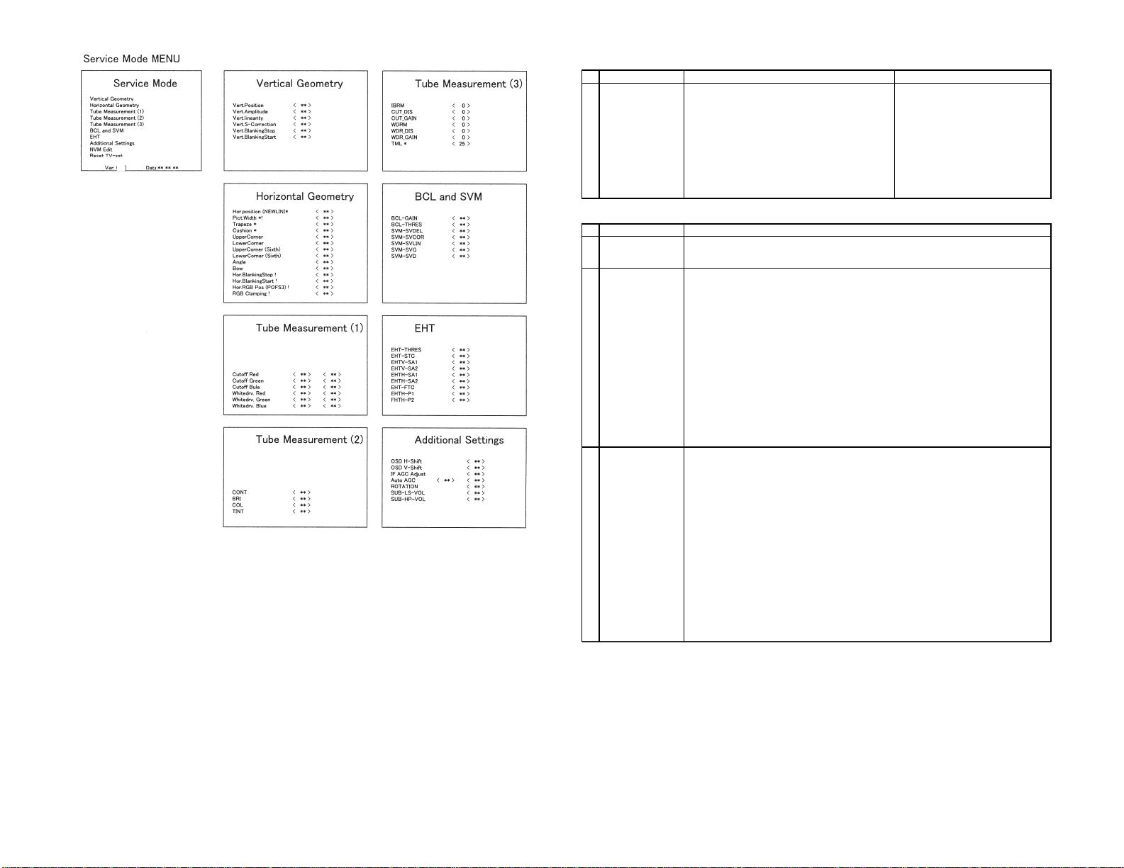
FUNCTION OPERATION CHECKING (1) (VIDEO & AUDIO)
NO
1
2
3
4
5
6
7
8
ADJUSTMENT POINT
CONTRAST
COLOUR
BRIGHTNESS
SHARPNESS
TINT
POWER SAVE
WHITE TEMP
NORMAL
ADJUSTMENT CONDITION / PROCEDURE
(1) Receive "Monoscope Pattern" signal.
(2) Press to Menu mode, then select Picture Mode and set
to select CONTRAST.
(3) Press Volume Up/Down key to check whether the
CONTRAST effect is OK or not.
(1) Receive "Colour Bar" signal.
(2) Press to Menu mode, then select Picture Mode and set
to select COLOUR.
(3) Press Volume Up/Down key to check whether the
COLOUR effect is OK or not.
(1) Receive "Monoscope Pattern" signal.
(2) Press to Menu mode, then select Picture Mode and set
to select BRIGHTNESS.
(3) Press Volume Up/Down key to check whether the
BRIGHTNESS effect is OK or not.
(1) Receive "Monoscope Pattern" signal.
(2) Press to Menu mode, then select Picture Mode and set
to select BRIGHTNESS.
(3) Press Volume Up/Down key to check whether the
BRIGHTNESS effect is OK or not.
(1) Receive "NTSC Colour Bar" signal thru AV in.
(2) Press to Menu mode, then select Picture Mode and set
to select TINT.
(3) Press Volume Up/Down key to check TINT, UP for
GREEN direction and DOWN for RED direction whether
is OK or not.
(1) Receive "Monoscope Pattern" signal.
(2) Set FEATURE to select SAVE.
(3) Press Volume Up/Down key to check the POWER SAVE
effect is OK or not. and whether LED(POWER SAVE)
light up or not.
(1) Receive "Monoscope Pattern" signal.
(2) Press to Menu mode, then select Picture Mode and set
to select WHITE TEMP.
(3) Press Volume Up/Down key to check WHITE TEMP
Option.
(1) Once in PICTURE Mode, and the NORMAL key is
pressed, all the settings will be present to normal setting.
(Normal setting value for every mode, refer on the
following figure).
WAVEFORM OR OTHERS
standerd movie music news
CONTRAST 50 60 45 45
COLOUR 0 0 5 5
BRIGHT 0 5 5 0
TINT 0 0 0 0
SHARPNESS 0 0 0 0
PICTURE NR LOW LOW LOW LOW
WHITE TEMP. 0 10 0 0
CHECKING FUNCTION OPERATION (2) (VIDEO & AUDIO) CONTINUED
NO
9
10
11
12
13
ADJUSTMENT POINT
COLOUR SYSTEM
SOUND SYSTEM
VOLUME
BALANCE
BASS
ADJUSTMENT CONDITION / PROCEDURE
(1) Receive the "PAL COLOUR BAR" signal, press the
COLOUR SYSTEM key to select modes except PAL,
check the COLOUR is not working properly.
Then, select the "PAL" mode. Check again its colour so
that it is working properly.
(2) Receive "SECAM COLOUR BAR" signal, press
COLOUR SYSTEM key to select modes except SECAM,
check the COLOUR is not working properly.
Then, select the "SECAM" mode. Check again its colour
so that it is working properly.
(3) Receive "NTSC 3.58 COLOUR BAR" signal, press
COLOUR SYSTEM key to select modes except NTSC
3.58, check the COLOUR is not working properly.
Then, select the "NTSC 3.58" mode. Check again its
colour so that it is working properly.
(4) Receive "NTSC 4.43 COLOUR BAR" signal thru AV,
press COLOUR SYSTEM key to select modes
except NTSC 4.43, check the COLOUR is not working
properly.
Then, select the "NTSC 4.43" mode. Check again its
colour so that it is working properly.
(1) Receive "PAL-D/K" signal, press the "SOUND SYSTEM"
to select B/G, I, M Check the sound output is not working
properly.
Select D/K and check the sound output to make sure it is
working properly.
(2) Receive "PAL-I" signal, press the "SOUND SYSTEM"
to select B/G, D/K, M Check the sound output is not
working properly.
Select I and check the sound output to make sure it is
working properly.
(3) Receive "PAL-B/G" signal, press the "SOUND SYSTEM"
to select I, D/K, M Check the sound output is not
working properly.
Select B/G and check the sound output to make sure it is
working properly.
(4) Receive "NTSC-M" signal, press the "SOUND SYSTEM"
to select I, D/K, B/G Check the sound output is not
working properly.
Select M and check the sound output to make sure it is
working properly.
(1) Receive "E-5ch Monoscope Pattern" signal.
(2) Press Volume Up/Down key to check whether the
VOLUME effect is OK or not.
(1) Receive "E-5ch Monoscope Pattern" signal.
(2) Press to Menu mode, then select Sound Mode and set
to select BALANCE.
(3) Press Volume Up/Down key to check whether the
Left-to-Right BALANCE effect is OK or not.
(1) Receive "E-5ch Monoscope Pattern" signal.
(2) Press to Menu mode, then select Sound Mode and set
to select BASS.
(3) Press Volume Up/Down key to check whether the
BASS effect is OK or not.
WAVEFORM OR OTHERS

8
SX76NF200
CHECKING FUNCTION OPERATION (2) (VIDEO & AUDIO) CONTINUED
NO
14
15
16
ADJUSTMENT POINT
TREBLE
SUPER BASS
VOLUME Headphone
ADJUSTMENT CONDITION / PROCEDURE
(1) Receive "E-5ch Monoscope Pattern" signal.
(2) Press to Menu mode, then select Sound Mode and set
to select TREBLE.
(3) Press Volume Up/Down key to check whether the
TREBLE effect is OK or not.
(1) Receive "E-5ch Monoscope Pattern" signal.
(2) Press to Menu mode, then select Sound Mode and set
to select SUPER BASS.
(3) Press Volume Up/Down key to check whether the
SUPER BASS effect is OK or not.
(1) Receive "E-5ch Monoscope Pattern" signal.
(2) connect Headphone.
(3) Press to Menu mode, then select Feature Mode and set
to select HEADPHONE.
(4) Press Volume Up/Down key to check whether the
VOLUME effect is OK or not.
WAVEFORM OR OTHERS
CHECKING FUNCTION OPERATION (WIDE MODE)
NO
1
2
3
ADJUSTMENT POINT
WIDE MODE
V-SIZE
in wide mode
V-SCROLL
in wide mode
ADJUSTMENT CONDITION / PROCEDURE
(1) Receive "Monoscope Pattern" signal.
(2) Press WIDE key to check change WIDE mode
PANORAMA/FULL/NORMAL/ZOOM14:9/CINEMA
(1) Receive "Monoscope Pattern" signal.
(2) Select PANORAMA, ZOOM14:9, and CINEMA mode.
(3) Select V-SIZE, Press Volume Up/Down key to check
whether the V-SIZE effect is OK or not.
(1) Receive "Monoscope Pattern" signal.
(2) Select PANORAMA, ZOOM14:9, and CINEMA mode.
(3) Select V-SCROLL, Press Volume Up/Down key to check
whether the V-SCROLL effect is OK or not.
WAVEFORM OR OTHERS
CHECKING FUNCTION OPERATION (TEXT MODE)
NO
1
2
ADJUSTMENT POINT
TEXT
TEXT key
ADJUSTMENT CONDITION / PROCEDURE
(1) Receive E-10ch signal.
(2) Press TEXT key to check change TEXT mode
TELETEXT mode / MIXED mode / TEXT off.
(1) Receive E-10ch signal.
(2) Press HALF PAGE, HOLD, REVEAL, CLOCK, CANCEL,
LIST, INDEX, and RESET key to check whether each
effect is OK or not.
WAVEFORM OR OTHERS
CHECKING FUNCTION OPERATION (AV MODE)
NO
1ADJUSTMENT POINT
AV MODE key ADJUSTMENT CONDITION / PROCEDURE
(1) Receive "Monoscope Pattern" signal.
(2) Press AV MODE key to check change AV MODE mode
STANDERD/MOVIE/MUSIC/NEWS
WAVEFORM OR OTHERS
8-1
CHECKING FUNCTION OPERATION (Twin Screen,PinP)
NO
1
2
3
4
5
ADJUSTMENT POINT
Twin Screen
(ON-OFF)
(Picture quality)
P in P
(ON-OFF)
(SIZE)
(MOVE)
P out P
(ON-OFF)
(MOVE)
FREEZE
CH-SCAN
ADJUSTMENT CONDITION / PROCEDURE
(1) Press "Twin Screen" key.
(2) Recive "E-5ch Monoscope Pattern" signal at SUB ch.
(3) Check the picture quality.
(4) Receive "E-12ch Colour bar" signal at SUB ch.
(5) Check the colour level.
(1) Press "P in P" key.
(2) Check the picture quality of SUB picture.
(3) Press "P in P" key.
(4) Check the SIZE of SUB picture.
(5) Press "MOVE" key.
(6) Check the position of SUB picture.
(1) Select NORMAL in Wide mode.
(2) Press to "P in P" key.
(3) Check the picture quality of SUB picture.
(4) Press "MOVE" key.
(5) Check the position of SUB picture.
(1) Receive "LIVE picture" signal.
(2) Press "P in P" key.
(3) Check the LIVE and FREEZE pictures.
(1) Press "CH-SCAN" key.
(2) Check the multi pictures.
WAVEFORM OR OTHERS
8-2

9
SX76NF200
TROUBLE SHOOTING FLOWCHART
NO PICTURE
Does the snow noise appear on
the CRT at max contrast and
brightness control?
Does approx.30V appear
at pin (9) of TU201(tuner) Check L202, D759 and
R761
Check TU201 and their
peripheral parts.
Check pin(1) and (2) of
IC201
Check pin(12) of (SE)
connector
Does noise or signal appear?
Check IC4003 RGB output
Normal?
Check pin(3) of IC1801,
IC1802, IC1803 Signal or
Noise?
Check R651(Heater), Screen
connection and Peripheral
circuits of T630(FBT) and CRT
Check TU201(tuner),
SF201 and Peripheral
parts.
Check IC201, Q205 and
their Peripheral circuits.
Check IC4003 and their
Peripheral circuits.
Check "KY" connection,
IC1801, IC1802, IC1803
and their Peripheral circuits
Snow noise increase No Snow noise
(Noise or signal appear)
(Noise)
(Signal)

10
SX76NF200
TROUBLE SHOOTING FLOWCHART
NO SOUND
Check sound setting by R/C.
Siganl should be received.
Check C1302(C1309) Voltage
Approx. 13V(-13V)
Check IC1301, IC1302 and Speaker
0V
Check L1302, L1303
D746 and D748

11
SX76NF200
TROUBLE SHOOTING FLOWCHART
NO FUNCTION (NO SOUND AND NO PICTURE)
Is D2201(LED) on a light?
Check 3pin of (SD)
connector
Check C2751 Voltage
Approx. 6V Check C2705 Voltage
Refer to "No
Picture", trouble
shooting
Check IC2700
GREEN RED
Approx. 320V
Completely 0V
No Input Pulse
Check Vertical
Circuit
Check IC1001 62pin
RY701
Check R2702,
F701 and "AA"
connection
0V
No Light
Check Q1002,
Q1001

12
SX76NF200
TROUBLE SHOOTING FLOWCHART
NO VERTICAL SCAN
Check the Voltage at pin(15)(1)
of IC502
Normal approx. 14V
Check IC502 and related circuits
Check D613, D615,
R647 and R646
Check IC4003 and
peripheral parts
Check vertical trigger pulse at
pin(12)(13) of IC502

13
SX76NF200
WAVEFORMS

14
SX76NF200

15
SX76NF200

16
SX76NF200
CHASSIS LAYOUT

17
SX76NF200

18
SX76NF200
BLOCK DIAGRAM
PWB-A MAIN UNIT

19
SX76NF200

20
SX76NF200
PWB-B POWER UNIT
Table of contents
Other Sharp TV manuals

Sharp
Sharp 27SF560 User manual

Sharp
Sharp LD-26SH1U User manual

Sharp
Sharp LC-40LE810E User manual

Sharp
Sharp LC-12A2E User manual

Sharp
Sharp LC-13S1UB User manual

Sharp
Sharp AQUOS LC-40N5000U User manual

Sharp
Sharp LC-32CHE5100E(W) User manual

Sharp
Sharp 40AJ2K User manual

Sharp
Sharp CN27S10 User manual

Sharp
Sharp 8C221 User manual

Sharp
Sharp 34H-F200 User manual

Sharp
Sharp 21FL94 User manual

Sharp
Sharp 14LT-45C User manual

Sharp
Sharp 21LF-90H User manual

Sharp
Sharp LC-19SH7E Quick start guide

Sharp
Sharp 70GS-64SDE User manual

Sharp
Sharp LC-32LD135E User manual

Sharp
Sharp Aquos UQ17U User manual

Sharp
Sharp 20F540 XFlat User manual

Sharp
Sharp 21FL91 User manual