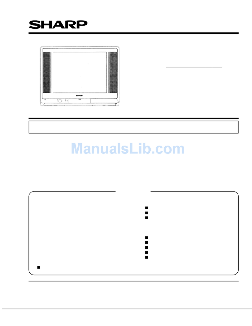
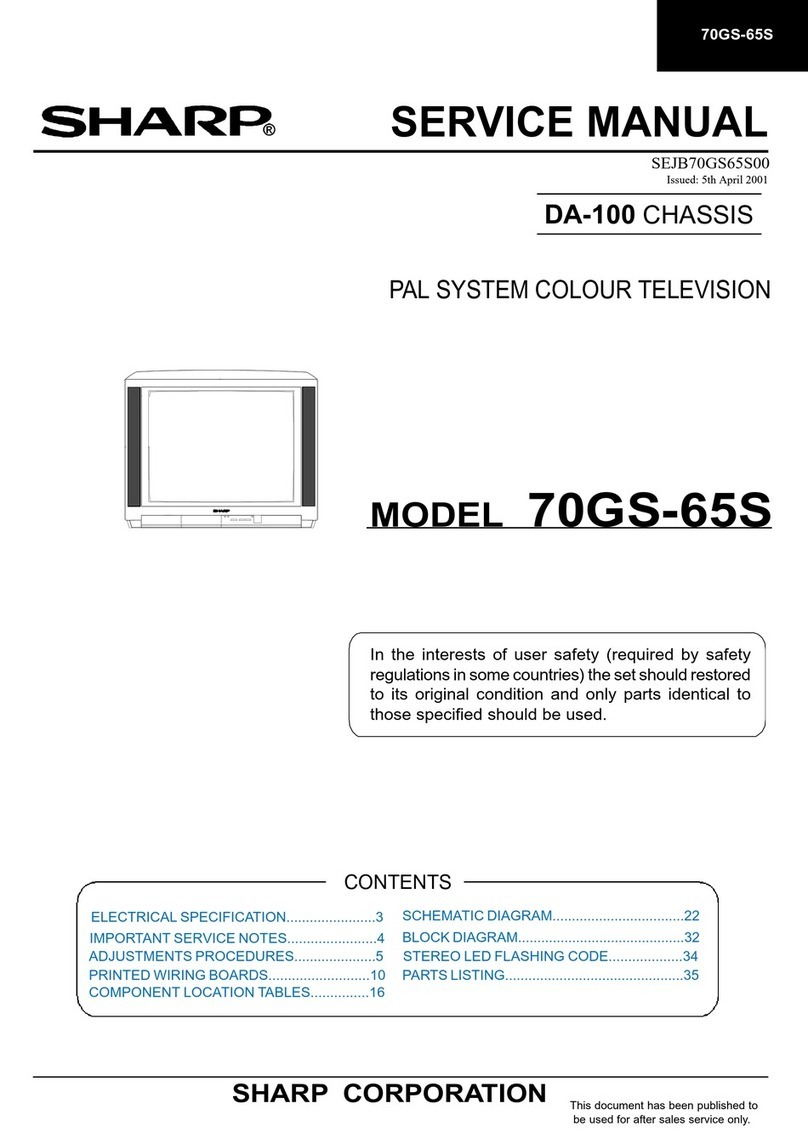
Sharp 63CS-03SC User manual


SERVICE MANUAL
SELF63DS03S/3
CA10-CHASSIS
PALSYSTEM COLOUR TELEVISION
Inthe interestsof user safety(requiredby safety
regulationsinsomecountries) the set should berestored
to itsoriginal condition andonly parts identicalto those
specified should beused.
ELECTRICAL SPECIFICATION
.................2
SCHEMATIC DIAGRAM
.............................9
IMPORTANT SERVICE NOTES
................2
BLOCK
DIAGRAM
.....................................11
SERVICE ADJUSTMENTS
........................3
PARTS LIST
..............................................13
PRINTED WIRING BOARDS
.....................7
SHARP CORPORATION

ELECTRICAL SPECIFICATIONS
Aerial InputImpedance
...................75
ohm
unbalanced
Power
Input
..............................220/240
Volts AC 50 Hz
Convergence
............................Self
Converging System Power Consumption atStand-by..............................3W
Focus.........................................Bipotential
electrostatic Power Consumption
...........................................90
Wh
Audio PowerOutput Rating
.................10+10W
(M.P.O.)
Speakers Size
...............................................
13cmX6cm
Picture IFCarrier Frequency
......................38.9
MHzSpeaker Coil
Impedance
........................................8
ohm
a)
Sound IFCarrier Frequency
...................33.4
MHzSweep Deflection
...........................................Magnetic
b)Sound IFCarrier Frequency .................33.16MHzTuningRanges ........................48.25MHz - 855.5 MHz
Colour Sub-Carrier Frequency .................34.47MHzCATV Special channels
(Nominal)
Specifications are subject to change without prior
notice .
WARNING
The chassis inthis receiver ispartially hot.Use anisolation transformer between the linecord plugand power
receptacle, when servicing this chassis.
Toprevent electric shock, do notremove cover. Nouser-serviceable parts inside.Refer servicing to qualified
servicepersonnel.
IMPORTANT SERVICE NOTES
Maintenance and repair of this receiver should becarried out by qualified service personnel only.
SERVICING OF HIGHVOLTAGE SYSTEM AND PICTURE TUBE
When servicing the high voltage system, remove static charge from itby connecting a 10k ohm resistor in
series with an insulated wire(such astest probe) between picture tube ground tag and highvoltage lead.(AC
linecord shouldbedisconnected from AC outlet).
1.Picture tube inthis receiver employs integral implosion protection.
2.Replace with tube of the same type number for continuedsafety.
3.Donot lift picture tube bythe neck.
4.Handlethe picture tube only when wearing shatterproof goggles and after discharging the highvoltage
completely.
X-RAY
This receiver isdesigned so that any X-Ray radiationiskept to an absolute minimun.Since certain malfunctions
ar servicing may produce potentially hazardous radiation with prolonged exposure atclose range, the following
precautions should beobserved.
1.When repairing the circuit, besure notto increase the highvoltage to more than 30.0kV (atbeam 1000 U.A)
for the set.
2.Tokeep the set ina normaloperation, besure to make itfunction on 23.5kV + 1.5kV(at beamlOOO ,nA)in
the case of the set. The set has been factoryadjusted to the above mentioned highvoltage. Ifthere isa
possibility that highvoltage fluctuates as result of the repairs,never forget to check forsuch highvoltage
after the work.
3.Donotsubstitute a picture tube with unauthorized types orbrandswhich may cause excess X-Ray radiation.
BEFORE RETURNING THE RECEIVER
Inaddition to the checks necessary as a result of a repair havingbeen carried out, thefollowing additional
safety checks should also bemadebefore returning the unitsto the user.
1.Inspectalllead insulation to make certain that leads are notpinchedor that harwareisnotlodged
between the chassis and other metal parts inthe receiver.
2.Inspect allprotective devices such as non-metallic control knobs,, insulatingfishpapers, cabinet backs,
adjustament and compartament covers or shields,insolation resistor-capacity networks, mechanical
insulators,etc.

SERVICE ADJUSTMENTS ——
All the adjustments required for this chasis will bedone inService Mode, except G2 and Focus.
•G2ADJUSTMENT
1.Receive cross hatch pattern signal.
2. Set contrast to 80/100andbrightness to 40/100.
3.Connect the oscilloscope to the red cathode and adjust G2
to read145Von the sensor pulseas inbelow drawing:
NOTE:
Osciloscope should beadjustated for vertical
TV field trigger and synchronized with video signal.
•SERVICE MODE FUNCTION
Thismode function isprovided to assist with the settings of those adjustment thatmayvary from one
Picture Tube to another, or between models.
Inorder to usetheService Mode
1.Connect Test Pattern signal to antenna terminal.
2.Press main switch to "OFF".
3.Press volume-down and channel-up buttons and mainswitch to "ON" simultaneously.
4.Service modeisnow entered.
The required adjustments can then bemade from the Remote Control Unit.
The onlybuttons required are the following:
Up/Down-channel formovement inadjustment options menu; Up/Down-volume are used to carry outan
adjustmentinsaidmenu;ON/OFFisusedto memorize a new adjustment.
Toexit service mode, press mainswitch to off.
Adjustment menuisas follows:
—SERVICE SOFTWARE — RED GAIN
—IFPLLADJUSTMENT — GREEN GAIN
—AGC TAKE OVER POINT — BLUEGAIN
—EAST WEST WIDTH — ALTER NVM PAG
—HORIZONTAL SHIFT— ALTER NVM POS.
—VERTICAL LINEARITY — ALTER NVM VAL
—VERTICAL AMPLITUDE — TELETEXT MIX MODE CONTRAST (ONLY FOR70DS05S)
—VERTICAL SHIFT— TELETEXT CONTRAST (ONLY FOR70DS05S)
—— S.CORRECTION — OSD CONTRAST (ONLY FOR70DS05S)
—EAST WEST PARABOLA — OPC VALUE (ONLYFOR70DS05S)
—EAST WEST CORNER — AUTOINSTALLATION ON/OFF
—EASTWEST TRAPEZIUM
3

•IFPLLADJUSTMENT
•a)Receiver the "COLOUR BAR" signal,CH69 (855.25 Mhz).
b)Push POWER button on Remote Control. Setting ismadeautomatically.
c) Toexit Service Mode, press mainswitch to OFF.
•AGCTAKE OVER POINT
a)Receive the "COLOUR BAR" signal (Signal strength: 57dB/uV)
b)PushCH upbutton. Setting ismade automatically.
c)Toexit Service Mode, press mainswitch to OFF.
GEOMETRY ADJUSTMENT PROCEDURE
Adjustment Note:
The procedure formaking adjustments to vertical corrections isasfollows:
-Adjust VERTICAL LINEARITY
-Adjust S. CORRECTION
-Adjust VERTICAL SHIFT
-Adjust VERTICAL AMPLITUDE
The procedure formaking adjustments to horizontal corrections isas follows:
-Set E-W WIDTH to minimum
-Adjust HORIZONTAL SHIFT
-Adjust E-W PARABOLA
-Adjust E-W WIDTH
-Adjust E-W TRAPEZIUM
-Adjust E-W CORNER
•EAST - WEST WIDTH
a)Receive Philips pattern signal.
b)When volume-up button ispressed, horizontal scanning increases.
c)When volume-down button inpressed, horizontal scanning decreases.
d)Adjust the horizontal amplitude to obtain9%overscan (fig. 1).
•HORIZONTAL SHIFT
a)Receive Philips pattern signal.
b)When volume-up button ispressed, picture moves to theleft.
c)When volume-down button ispressed, picture moves to the right.
d)Adjust the horizontal location to obtain picture centering (fig. 2).
•VERTICAL SLOPE
a)Receive center cross chart from patterngenerator.
b)Adjust horizontal lineoff thecross figure tocoincidewith theedgeof the
blackareainthecenter ofC.R.T.(fig.3).
4

•VERTICAL AMPLITUDE
a)Receive Philips pattern signal.
b)When volume-up button ispressed, vertical sizepictureincreases.
c)When volume-down button ispressed, vertical size of picture decreases.
d)Adjust the vertical size to obtain overscan (fig. 4).
•VERTICAL SHIFT
a)Receive Philips pattern signal.
b)When volume-up button ispressed, picture moves up.
c)When volume-down ispressed, picture moves down.
d)Adjust the horizontal locationto obtainpicture centering(fig.5).
•S-CORRECTION
a)Receive Philips pattern signal.
b)When volume-up button ispressed, upper andlower scanning decreases,
and center scanning increases.
c) When volume-down button ispressed, upper and lower scanning increases,
andcenter scanning decreases.
d)Adjust the S-correction to obtain a balance between upper,lowerandcenter.
.
(tig.
6).
•EAST - WEST PARABOLA
a)Receive Philips pattern signal.
b)When volume-up button ispressed, sidepincushion changes from
pincushion shape.
c)When volume-down button ispressed, side pincushion changes from barrel
shape.
d)Adjust the E-W PARABOLA to obtain condition as (fig. 7).
•EAST - WEST CORNER
a)Receive Philips pattern signal.
b)When volume-down button ispressed, side pincushion changes from
pincushion shape.
c)When volume-up buttonispressed, sidepincushionchangesfrom barrelto
pincushion shape.
d)Adjust the E-W CORNER to obtain condition as in(fig. 8).
•EAST - WEST TRAPEZIUM
a)Receive Philipspattern signal.
b)When volume-up buttonispressed, sidepincushionchanges.
c)When volume-down button ispressed, sidepincushionchanges.
d)Adjust the E-W TRAPEZIUM to obtainconditionasin(fig.9).
5

COLOUR ADJUSTMENT
Thefollowing adjustments are onlyrequiredwhen thePictureTubeischanged.
•RED GAIN / GREEN GAIN / BLUE GAIN
a)Usingbrightnessandcontrastbuttons,selectaluminanceof==110NITS.
b)Operate againinService Mode andselect location RED GAIN / GREEN GAIN / BLUE GAIN, to
obtain colour coordinates:
X=0.290 ±0.015
Y=0.284±0.015
Toincrease press volume-up button andto decrease press volume-down button
RED GAIN alter "X"coordinate
GREEN GAIN alter "Y"coordinate
BLUE GAIN alter "X" and"Y" coordinate
c)The changes introduced can bememorized bypressing button(bonTV set.
d)Exit Service Mode and check colour coordinates "X" and"Y" at20 and110NITS. Itmaybe
necessary to repeat procedure 1 and 2 of COLOUR ADJUSTMENT.
ACCESS TO NVM
Press CHA to move inthe following secuence:
ALTER NVM PAG ->ALTER NVM POS->ALTER NVM VAL
to alter preseting adjustments, press up/down-volume buttons on ALTER NVM VAL.
ACAUTION: Donot change NVM VALUE to avoid risk of serious damages toTV set.
CONTRAST ADJUSTMENT (Only for 70DS05S)
Up/Down-volume buttons are used to adjust the contrast of the following items:
—TELETEXT MIX MODE CONTRAST •
—TELETEXT CONTRAST
—OSD CONTRAST
OPC VALUE (Only for70DS05S)
Shows reading of detected illuminated value byO.P.C.(Optical Picture Control) to check
function.
AUTO INSTALLATION OFF/ON
When ON isselected, the TV will perform the autoinstallation secuence as soon as service mode
isremoved.

PICTURE TUBE
PARTS LIST
REPLACEMENT PARTS
Replacement parts which have special safety characteristics
identified inthis manual.Electrical components having such feat
are identified byA inthe Replacement Parts list.
The useof a substitute replacement partwhich doesnothave
same safetycharacteristics as the factoryrecommended is
permitted. Replacement parts notshown inthis service manual
create shockfire, or other hazards.
HOW TO ORDER REPLACEMENT PARTS
Tohave your order completed promptly andcorrectly pleasesu
the following information.
1.MODEL NUMBER2.REF.NO.
3. PART NO.4. DESCRIPTION
5. CODE 6. QUANTITY
*MARK: SPARE PARTS DELIVERY SECTION
REF NO.
A
A
A
A
PRINTEDWIRINGBOARDSASSEMBLES
(Not replacement item)
PWB-A
PWB-A
PWB-A
PWB-B
PWB-B
PWB-B
MOTHER UNI
TUNER
TU
0201
INTEGRATED CIRCUITS
1C
0101
1C
0102
1C
0103
1C
0104
1C
0104
1C
0105
1C
0105
1C
0105
1C
0106
1C
0107
1C
020'1
1C
0202
1C
0301
1C
0302
1C
0303
1C
0304
1C
0305
1C
0401
1C
0501
1C
0502
1C
0701
1C
0702
A1C0703
A1C0704
PARTS NO.
VB59EAK711TN
VB66EAK7111-N
CCILG0403BMVO
CCILG0404BMVO
DUNTK7215CJV1
DUNTK7215CJVO
DUNTK7215CJV3
DUNTK7216BMV1
DUNTK7216BMVO
DUNTK7216BMV3
RTUNH0123BMZZ
RH-IX1629BMZZ
VHIPST529C2-1
RH-IX1603BMZZ
RH-IX1588BMZ2
RH-IX1603BMZZ
CH-IX1600CJSC
CH-IX1600CJSB
CH-IX1642CJS3
RH-IX1635BMZZ
RH-IX1601BMZZ
VHITDA8844/-1
RH-IX0037CEZZ
VHIBA4558//-1
RH-IX1556BMZZ
RH-IX1556BMZZ
VHIM5218L//-1
RH-IX1633BMZZ
RH-IX1602BMZZ
RH-IX1556BMZZ
VHIBA4558//-1
VHIPST529C2-1
RH-IX1646BMZZ
RH-FX0103BMZZ
RH-FX0103BMZZ
*
S
S
S
S
S
S
S
S
S
S
S
S
S
S
S
S
S
S
S
S
S
S
S
S
S
S
S
S
S
S
S
S
S
S
S
DESCRIPTION
C.R.T 25"
C.R.T.28"
Degaussing Coil 25"
Degaussing Coil 28"
Mother Unit63DS03S
Mother Unit 70DS03S
Mother Unit 70DS05S
C.R.T. Socket Unit 63DS03S
C.R.T. Socket Unit70DS03S
C.R.T. Socket Unit70DS05S
Tuner
SAB-C161K-L16Q
PST529C
NVM 70DS05S
NVM 63/70DS03S
NVM 70DS05S
EPROM 63DS03S
EPROM 70DS03S
EPROM 70DS05S
STV5346
O.P.C.
TDA8844
UPC574J 33V
BA4558
BA10393SOPS
BA10393SOPS
M5218L
MSP3400C
HEF4053
BA10393
BA4558
PST529C
ST6203B
MOC8105SR2V
MOC8105SR2V
are
ures
'the
not
pply
CODE
CW
CW
AT
AV
—
BA
AY
AD
AV
AQ
AV
AX
AX
BA
AY
AH
BD
AD
AC
AD
AD
AF
BB
AE
AD
AC
AD
AL
AD
AD
REF.
NO.
A|C0705
1C
0706
1C
2400
1C
2401
1C
2403
TRANSISTORS
Q
0110
Q
0111
Q0202
Q0203
Q
0301
Q0302
'Q0303
Q0304
Q0305
Q0306
Q0307
Q0308
Q0309
Q
0312
Q
0313
Q
0315
Q
0316
Q0403
Q0404
Q
0501
Q0502
Q0503
Q0504
Q0505
00506
Q0507
Q
0601
Q0602
Q0704
00705
Q0706
Q0707
Q0708
Q0709
Q2400
DIODES
D
0103
D
0104
D
0105
D
0106
.
D
0111
D
0113
D
0114
D
0201
D
0251
D
0301
D0302
D0303
D0304
D0305
D0306
D0307
D0308
D0309
D
0310
PARTS NO.
RH-FX0103BMZZ
RH-IX1478BMZZ
RH-IX1567BMZZ
RH-IX1656BMZZ
RH-IX1556BMZZ
VS2SC2412KQ-1
RH-TX0143BMZZ
VS2SC2412KQ-1
VS2SC2412KQ-1
VS2SC2412KQ-1
VS2SC2412KQ-1
VS2SC2412KQ-1
RH-TX0171BMZZ
RH-TX0172BMZZ
RH-TX0171BMZZ
RH-TX0172BMZZ
VS2SA1037KQ-1
VS2SC2412KQ-1
VS2SA1037KQ-1
VS2SC2412KQ-1
VS2SC3326B/-1
VS2SC3326B/-1
VS2SC2412KQ-1
VS2SC2412KQ-1
VS2SC2412KQ-1
RH-TX0171BMZZ
RH-TX0172BMZZ
VS2SC2412KQ-1
VS2SA1037KQ-1
VS2SC2412KQ-1
RH-TX0151BMZZ
RH-TX0152BMZZ
RH-TX0146BMZZ
RH-TX0144BMZZ
RH-TX0166BMZZ
RH-TX0102BMZZ
RH-TX0102BMZZ
VS2SA1037KQ-1
VS2SC2412KQ-1
RH-TX0130BMZZ
RH-TX0130BMZZ
VS2SC2412KQ-1
VS2SC2412KQ-1
VS2SC2412KQ-1
RH-DX0551BMZZ
RH-DX0551BMZZ •
RH-DX0551BMZZ
RH-DX0551BMZZ
RH-DX0045BMZZ
RH-EX0409BMZZ
RH-EX0546BMZZ
RH-DX0045BMZZ
RH-DX0045BMZZ
RH-DX0551BMZZ
RH-DX0551BMZZ
RH-DX0551BMZZ
RH-DX0551BMZZ
RH-EX0558BMZZ
RH-EX0558BMZZ
RH-EX0558BMZZ
RH-EX0558BMZZ
RH-EX0555BMZZ
RH-EX0555BMZZ
*
S
S
S
S
S
S
S
S
S
S
S
S
J
J
J
J
S
S
S
S
y
S
S
S
S
0
J
J
S
S
S
S
S
S
S
S
S
S
S
S
S
S
S
S
S
S
S
S
S
S
S
S
S
S
S
S
S
S
S
S
S
S
S
S
DESCRIPTION
MOC8105SR2V
L7808
SDA5273 SDIP52
DRAM
BA10393SOP8
2SC2412
BC557-B
2SC2412
2SC2412
2SC2412
2SC2412
2SC2412
IRFR9020TM
IRFR010TM
IRFR9020TM
IRFR010TM
BC807
2SC2412
BC807
2SC2412
2SC3326B
2SC3326B
2SC2412
2SC2412
2SC2412
^OOl^-tI£.
IRPR9020TM
IRFR010TM
2SC2412
BC807
2SC2412
2SD2391Q
BC846BLT1
2SD2153T100/W
BUH515
2SK2605
BC338
BC338
BC807
2SC2412
BC338-40
BC338-40
2SC2412
2SC2412
2SC2412
LL4148
LL4148
LL4148
LL4148
1N4148
Zener BZX79C5V6
Zener TZMC5V6
1N4148
1N4148
LL4148
LL4148
LL4148
LL4148
Zener TZMC18
Zener TZMC18
Zener TZMC18
Zener TZMC18
Zener TZMC13
Zener TZMC13
CODE
AD
AE
BG
AZ
AD
AA
AA
AA
AA
AA
AA
AA
AF
AE
AF
AE
AA
AA
AA
AA
AD
AD
AA
AA
AA
AF
AE
AA
AA
AA
AD
AA
AD
AK
AK
AB
AB
AA
AA
AB
AB
AA
AA
AA
AA
AA
AA
AA
AA
AA
AA
AA
AA
AA
AA
AA
AA
AA
AA
AA
AA
AA
AA

REF.
NO.
D
0311
D
0312
D0320
D
0321
D0322
D0323
D0324
D0325
D0326
D0327
D0328
D0329
D
0401
D0402
D0403
D0404
D0405
D0406
D0503
D
WDd
U»JU~+
D0506
D0507
D0508
D0509
D
0510
D
0511
D
0512
D
0513
D
0514
D
0515
D
0516
D
0517
D
0518
D
0519
D0520
D
0521
D0522
D
0601
D0602
D0603
D0604
D0605
D0607
D0608
D0609
D
0612
D
0613
D
0701
D0702
D0703
D0704
D0706
D0707
D0708
D0709
D
0710
D
0711
D
0712
D
0713
D
0715
D
0716
D
0717
D
0718
D
0719
D0720
D
0721
D0722
D0724
D0725
D0726
D0727
PARTS NO.
RH-EX0555BMZZ
RH-EX0555BMZZ
RH-DX0551BMZZ
RH-DX0551BMZZ
RH-DX0519BMZZ
RH-DX0519BMZZ
RH-DX0519BM2Z
RH-DX0519BMZZ
RH-EX0410BMZZ
RH-EX0547BMZZ
RH-EX0547BMZZ
RH-EX0547BMZ2
RH-EX0412BMZZ
RH-EX0412BMZZ
RH-EX0412BMZZ
RH-EX0412BMZZ
RH-DX0551BMZZ
RH-DX0551BMZZ
RH-EX0418BMZZ
RH-EX0418BMZZ
RH-DX0045BMZZ
RH-DX0045BMZZ
RH-DX0045BMZZ
RH-DX0045BMZZ
RH-DX0505BMZZ
RH-EX0413BMZZ
RH-DX0045BMZZ
RH-DX0045BMZZ
RH-DX0045BMZZ
RH-EX0413BMZZ
RH-DX0505BMZZ
RH-EX0558BMZZ
RH-EX0421BMZZ
RH-EX0546BMZZ
RH-DX0551BMZZ
RH-EX0550BMZZ
RH-EX0550BMZZ
RH-DX0551BMZZ
RH-DX0504BMZZ
RH-DX0299BMZZ
RH-DX0301BMZZ
RH-DX0591BMZZ
RH-DX0045BMZZ
RH-DX0593BMZZ
RH-DX0593BMZZ
RH-DX0505BMZZ
RH-DX0506BMZZ
RH-DX0555BMZZ
RH-DX0555BMZZ
RH-DX0555BMZZ
RH-DX0555BMZZ
RH-DX0045BMZZ
RH-DX0502BMZZ
RH-DX0502BMZZ
RH-DX0502BMZZ
RH-EX0408BMZZ
RH-DX0539BMZZ
RH-EX0419BMZZ
RH-DX0045BMZZ
RH-DX0045BMZZ
RH-EX0409BMZZ
RH-EX0810BMZZ
RH-DX0505BMZZ
RH-DX0505BMZZ
RH-DX0561BMZZ
RH-DX0505BMZ2
RH-DX0519BMZZ
RH-EX0405BMZZ
RH-EX0481BMZZ
RH-DX0045BMZZ
RH-DX0045BMZ2
*
S
s
S
s
s
s
s
s
s
s
s
s
s
s
s
s
s
s
s
s
s
s
s
s
s
s
s
s
s
s
s
s
SZener BZX79C18V
SI Zener TZMC5V6
S
S
S
S
S
S
S
S
S
S
S
S
S
S
S
S
S
S
S
s
s
s
s
s
s
s
s
s
s
s
s
s
s
s
s
s
s
DESCRIPTION
Zener TZMC13
Zener TZMC13
LL4148
LL4148
1N5819
1N5819
1N5819
1N5819
Zener BZX79C6V2
Zener TZMC6V2
Zener TZMC6V2
Zener TZMC6V2
Zener BZX79C7V5
Zener BZX79C7V5
Zener BZX79C7V5
Zener BZX79C7V5
LL4148
LL4148
Zener BZX79C13V
Zener BZX79C13V
1N4148
1N4148
1N4148
1N4148
1N4935
Zener BZX79C8V2
1N4148
1N4148
1N4148
Zener BZX79C8V2
1N4935
Zener TZMC18
LL4148
Zener TZMC8V2
Zener TZMC8V2
LL4148
1N4934
BY 228-20
BY
299
RGP10A50V
1N4148
RGP10D200V
RGP10D200V
1N4935
1N4936
RF2005
RF2005
RF2005
RF2005
1N4148
1N4005
1N4005
1N4005
Zener BZX79C5V1
BYT52M
Zener BZX79C15V 0,4W
1N4148
1N4148
Zener BZX79C5V6
Zener BZX79A6V2
1N4935
1N4935
RGP15J
1N4935
1N5819
Zener BZX79C3V9
Zener BZX79B5V6
1N4148
1N4148
CODE
AA
•
AA
AA
AA
AD
AD
AD
AD
AB
AA
AA
AA
AB
AB
AB
AB
AA
AB
AB
AA
AA
AA
AA
AB
AB
AA
MM
AA
AA
nM
AB
AB
AA
AA
AA
AA
AA
AA
AA
AB
AE
AD
AB
AA
AB
AB
AB
AB
AB
AB
AB
AB
AA
AA
AA
AA
AB
AC
AB
AA
AA
AA
AC
AB
AB
AD
AB
AD
AB
AB
AA
AA
REF.
NO.
D0730
D
0801
D0802
D0803
D0804
D0805
D0806
D0809
D
0810
D
0811
D
0812
D
0813
D0824
D2400
D
2401
LED0301
LED0302
PACKADGED CIRCUITS
APOR0701
X
0101
X0102
X0301
X0801
X2400
COILS
L
0201
L
0201
L0203
L
0301
L0302
L0303
L0304
L0305
L0306
L0307
L0308
L0309
L
0310
L
0311
L
0312
L
0313
L
0314
L
0315
L
0316
L
0317
L
0318
L
0501
L0502
L0503
L0504
L0505
L
0601
L0602
L0603
L0604
L0605
A
L
0701
L2400
T
0201-
CERAMIC FILTERS
CF 0202
CF
0701
SF
0201
PARTS NO.
RH-DX0045BMZZ
RH-EX0412BMZZ
RH-EX0412BMZZ
RH-EX0412BMZZ
RH-EX0412BMZZ
RH-DX0045BMZZ
RH-DX0045BMZZ
RH-EX0412BMZZ
RH-EX0549BMZZ
RH-EX0549BMZZ
RH-EX0549BMZZ
RH-DX0045BMZZ
RH-DX0045BMZZ
RH-EX0539BMZZ
RH-EX0548BMZZ
RH-PX0105BMZZ
RH-PX0105BMZZ
RMPTP0028CEZZ
RCRSB0235BMZZ
RCRSB0227BMZZ
RCRSB0203BMZZ
RCRSB0115BMZZ
RCRSB0214BMZZ
VP-DF121KOOOO
VP-DF120KOOOO
VP-DF120KOOOO
VP-DF100KOOOO
VP-DF100KOOOO
VRS-TQ2BD101J
VRS-TQ2BD101J
VRS-TQ2BD101J
VRS-TQ2BD101J
VRS-TQ2BD101J
VRS-TQ2BD101J
VRS-TQ2BD101J
VRS-TQ2BD101J
RCILP0236BMZZ
RCILP0236BMZZ
VP-CF3R3KOOOO
VP-CF3R3KOOOO
VP-CF3R3KOOOO
VP-CF3R3KOOOO
VP-DF3R3KOOOO
VP-DF3R3KOOOO
VP-CF3R3KOOOO
RCILP0105CEZZ
VP-CF3R3KOOOO
VP-CF3R3KOOOQ
VP-DF3R3KOOOO
VP-DF4R7KOOOO
RCILP0237BMZZ
RCILP0104CEZZ
RCILP0105CEZZ
RCILZ0599CEZZ
RCILF0111BMZZ
VP-DF3R3KOOOO
RCILDC238BMZZ
RFILC0020CEZZ
RFILC0121GEZZ
RFILC0275BMZZ
*
S
S
s
s
s
s
s
s
s
s
s
s
s
s
s
s
s
s
s
s
s
s
s
s
s
s
s
s
s
s
s
s
s
s
s
s
s
s
s
s
s
s
s
s
s
s
s
s
s
s
s
s
s
s
s
s
s
s
s
s
DESCRIPTION
1N4148
Zener BZX79C7V5
Zener BZX79C7V5
Zener BZX79C7V5
Zener BZX79C7V5
1N4148
1N4148
Zener BZX79C7V5
Zener TZMC7V5
Zener TZMC7V5
Zener TZMC7V5
1N4148
1N4148
Zener TZMC3VO
Zener TZMC6V8
LED
LED
,
P.T.C.
Crystal 16MHz
Crystal 13.875MHz
Crystal 18.432MHz
Crystal 4.43 MHz
Crystal 20.48MHz
120uH54DS03S
12uH
12,uH
10,uH
lOpH
1001/8WMetal Oxide
1001/8WMetal Oxide
1001/8WMetal Oxide
1001/8WMetal Oxide
1001/8WMetal Oxide
1001/8WMetal Oxide
1001/8WMetal Oxide
1001/8WMetal Oxide
100uH
100pH
3.3uH
3.3uH
3.3uH
3.3^H
3.3|^H
3.3uH
3.3nH
Coil
3.3^H
3.34H
3.3uH
4.7^H
150uH
Coil
Coil
Delay Line
Main Filter
3.3^iH
Adjust Coil
Filter5.5MHz(T5.5B)
Filter8MHz
SAW Filter G1984T901
CODE
AA
AB
AB
AB
AB
AA
AA
AB
AA
AA
AA
AA
AA
AA
AA
AC
AC
AG
AF
AG
AG
AG
AH
AB
AB
AB
AB
AB
AA
AA
AA
AA
AA
AA
AA
AA
AQ
AQ
AB
AB
AB
AB
AB
AB
AB
AG
AB
AB
AB
.
AB
AD
AG
AG
AG
AL
AB
AE
AE
AD
AK
14
This manual suits for next models
1
Table of contents
Other Sharp TV manuals

Sharp
Sharp 21V-FW100S User manual

Sharp
Sharp 21HF2-SF User manual

Sharp
Sharp 29K-FD1SA User manual

Sharp
Sharp LC-48CFE4042E User manual

Sharp
Sharp LC-50U35T User manual

Sharp
Sharp 32C241 User manual

Sharp
Sharp LC-46LE631E User manual

Sharp
Sharp 32R-S60 User manual

Sharp
Sharp 21LF2-RU User manual

Sharp
Sharp 21LF-90H User manual

Sharp
Sharp 27SC260R User manual

Sharp
Sharp AQUOSLC-42GX3H User manual

Sharp
Sharp 70ES-03SN User manual

Sharp
Sharp LC-20SH3X User manual

Sharp
Sharp 21S-FX10F User manual

Sharp
Sharp LC-70UI9362K Technical manual

Sharp
Sharp LC-24CHG6001KF Technical manual

Sharp
Sharp 27R-S100 User manual

Sharp
Sharp 14V-R70M User manual

Sharp
Sharp LC-40LE660X User manual