LC-46XL2E/S/RU
3
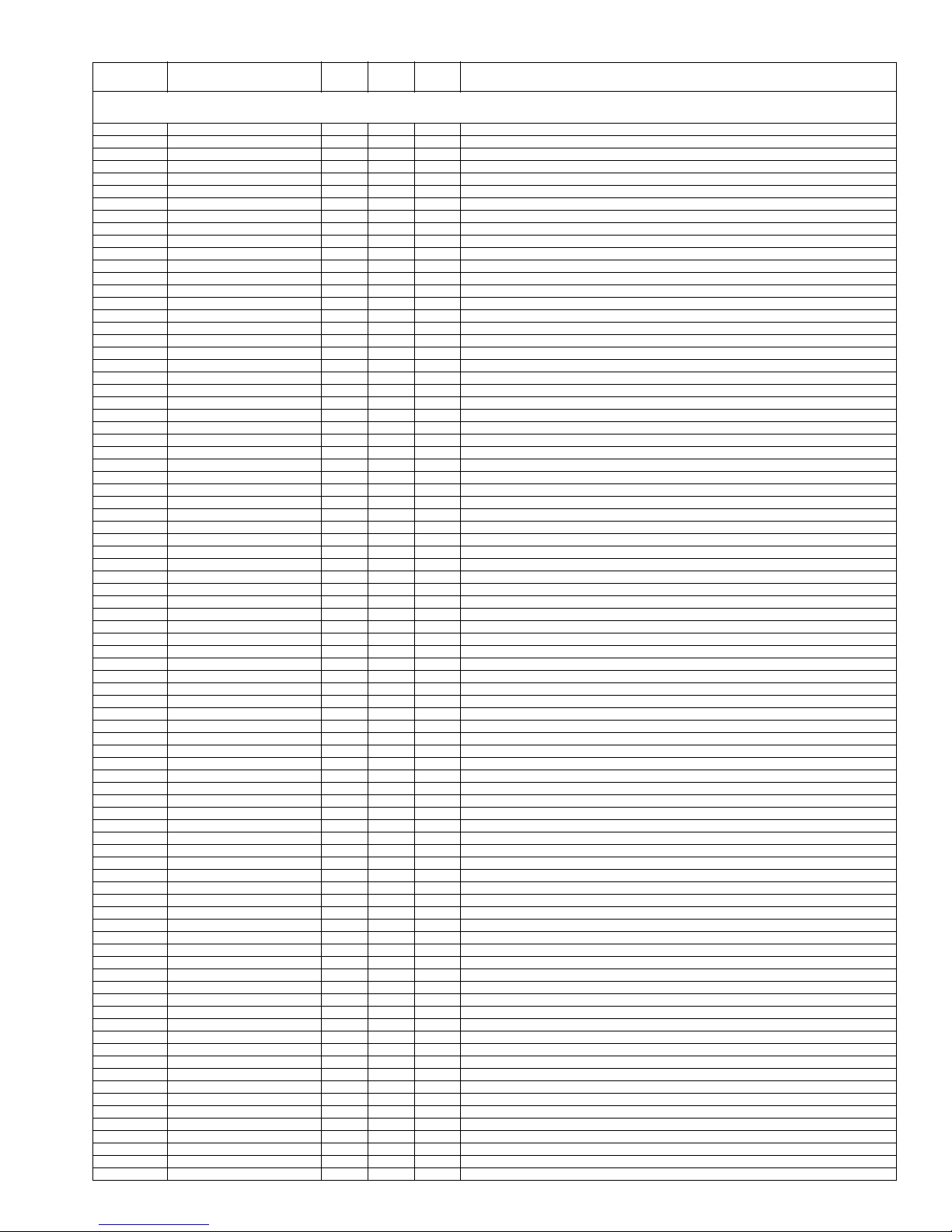
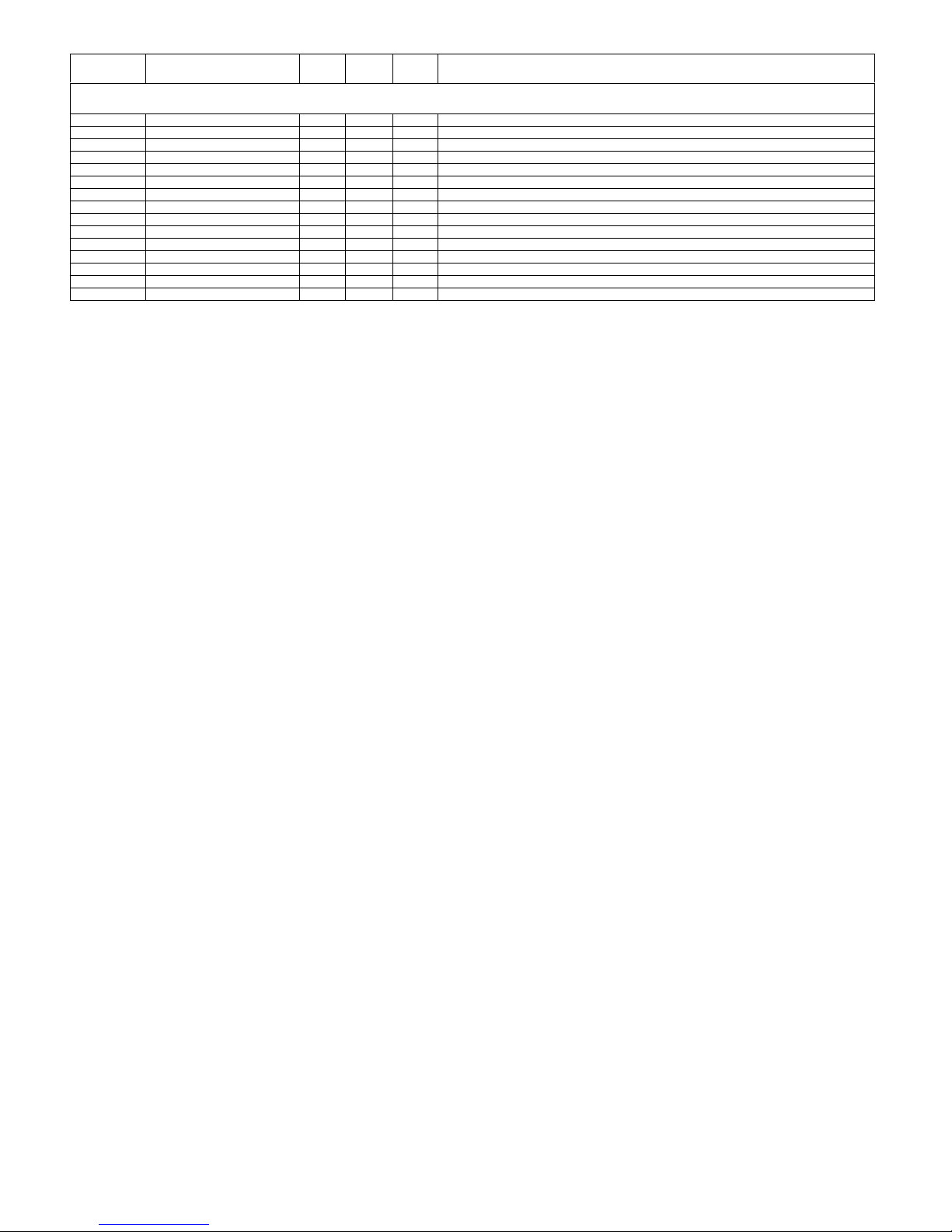
NO. PARTS CODE PRICE
RANK
NEW
MARK
PART
DELIVERY
DESCRIPTION
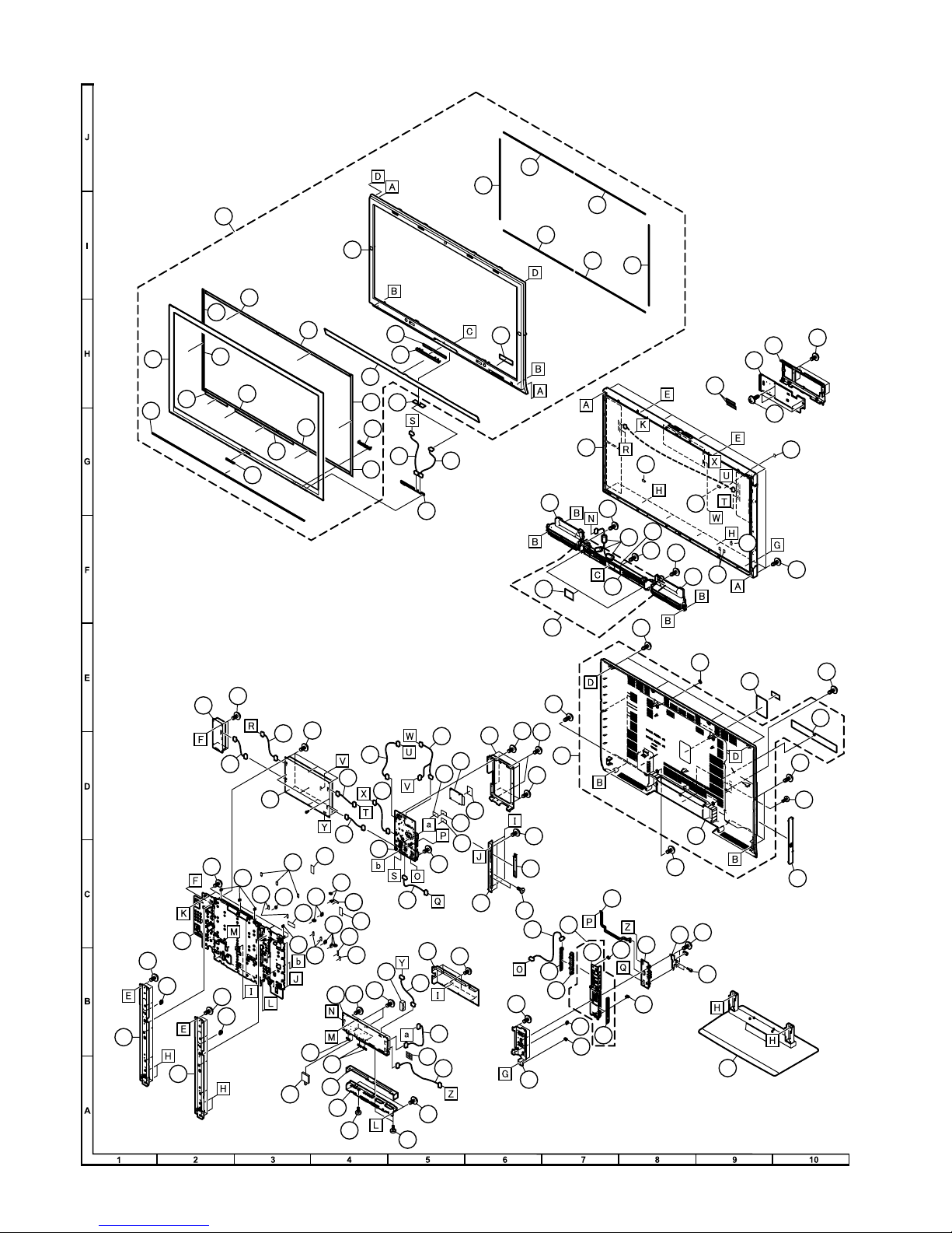
[1] CABINET PARTS
1CCABAB818WJ11 CE N P Front Cabinet Ass'y
1-1 Not Available - N - Front Cabinet
1-3 Not Available - N - Front Cover
1-4 HBDGBA061WJSA AF J Sharp Badge
1-5 Not Available - - Shine Trim
1-6 Not Available - N - Center Dec Holder
1-7 Not Available - N - Front Dec
1-8 Not Available - N - LED Decoration
1-9 Not Available - N - SP Sheet
1-10 Not Available - N - Mask Himeron, x6
1-11 Not Available - N - Front Cover Tape, x5
1-12 Not Available - N - Front Cover Tape, x5
1-13 PSPAZB624WJZZ AA N P Spacer
2CCABBB100WJ11 BT N P Rear Cabnet Ass'y
2-1 Not Available - N - Rear Cabnet
2-2 Not Available - N - Terminal Label
3CCOVAC336WJ11 AY N P Bottom Cover Ass'y
3-1 Not Available - - Bottom Cover F
3-2 PSPAHB307WJZZ AA P Bottom Cover SPD, x2
4CDAI-A397WJ12 AQ N P Stand Ass'y
5CCOVAC748WJ12 AU P MINI AV Key Cover Ass'y
5-1 Not Available - N - Side Key Cover
5-2 Not Available - S - MINI Terminal Label
6R1LK460D3LZ6DY N J 46" Full HD LCD Panel Module
7DUNTKE186FM01 CT N R MAIN Unit
8DUNTKE187FM01 BY N R TERMINAL Unit
9DUNTKE264FM01 AS N R R/C, LED Unit
10 DUNTKE266FM01 AR R KEY Unit
11 DUNTKE188FM01 BD R MINI AV Unit
12 DUNTKE270FM01 AS N R ILLUMINATION Unit
13 RDENCA231WJQZ BZ N R POWER Unit
14 RUNTKA311WJQZ BA N R AC Inlet Unit
15 LANGKB173WJ1A AN N R Side Terminal Angle
16 LCHSMA429WJFW AX N R Chassis Tray
17 LHLDFA036WJKZ AB - J Wire Holder (Tray), x3
18 LHLDWA133WJKZ AC N J Wire Holder (Tray), x4
19 LHLDWA143WJKZ AC - J Wire Holder (Tray), x12
20 LHLDWA144WJKZ AC N R Wire Holder (Terminal PWB)
21 LHLDWA151WJKZ AB - J Wire Holder (Tray), x6
22 LHLDWA163WJKZ AC - J Wire Holder (Tray), x4
23 LHLDWA172WJKZ AD - R Wire Holder (Tray)
24 PMLT-A487WJZZ AD N R Gasket (10x30x7)
25 PRDARA482WJ1W AV N R Main Radiator
26 PSLDMA702WJZZ AD - R Conductiv Shield (10x20), x5
27 PSLDMB154WJQZ AD - J 13x30x10 Gasket, x2
28 PSLDMB327WJFW N R Main Shiled
29 PSPAZB312WJKZ AD N J Spacer (25*25 T2.0)
30 PSPAZB313WJKZ AC - J Spacer (20*20 T2.0)
31 QCNCMA673WJZZ AG N J Connector (B_To_B_Plug_80)
32 QCNW-F946WJQZ AH N R Connecting Cord (AC:POWERAC)
33 QCNW-G634WJQZ AN N R Connecting Cord (PD:MAINPOWER)
34 QCNW-F948WJQZ AK N R Connecting Cord (PE:TERMINPOWER)
35 QCNW-G419WJQZ AP N R Connecting Cord (FE:MAINTERMINA)
36 QCNW-G015WJQZ AL N R Connecting Cord (SP:TERMINALSP)
37 QEARZA108WJFW AE N R Earth Plate(L)
38 QEARZA109WJFW AD N R Earth Plate(S), x2
39 RCORFA023WJZZ AK J Core (for SP Wire), x3
40 RTUDAA014WJQZ AZ N R Tuner
41 XBPS830P06000 AA - J Screw, x2 (FOR HDMI)
42 XJPS730P08WS0 AA - J Screw, x32 (Main Pow Termin)
43 LANGKB175WJ1A AL P Terminal Angle Bottom
44 LANGKB248WJFW AE P Scart Angle
45 QCNW-F950WJQZ BD R Connecting Cord (LW:MAINLCDCTL)
46 QCNW-F968WJQZ AH R Connecting Cord (PL:POWERLCDCTL)
47 QCNW-G010WJQZ AG R Connecting Cord (KM:MAINKEY)
48 QCNW-G011WJQZ AH P Connecting Cord (RA:MAINLED)
49 QCNW-G013WJPZ AN P Connecting Cord (US:MAINMINI_AV)
50 QCNW-G014WJQZ AS R Connecting Cord (VD:SUBMINI_AV)
51 QCNW-G016WJQZ AH R Connecting Cord (LA1:POWERINV_R)
52 QCNW-G017WJQZ AH R Connecting Cord (LA2:POWER-INV_L)
53 QCNW-G018WJQZ AH R Connecting Cord (LB:MAININV)
54 QPWBHE322WJQZ AX J FPC (HM:MAINMINI_AV)
55 XBBS830P08000 AA J Screw (for Scart), x2
56 XBBS930P04000 AA J Screw (for Tuner Fix), x1
57 XIPSN20P04000 AA N J Screw (for HDMI), x2
58 LANGKB186WJ1W AT N P Panel Support Ang, x2
59 LANGKB215WJ1W AM N P MINI AV Angle
60 PCOVP2605WJZZ AM N J Control Shield
61 PRDARA513WJFW AX N R Heat Sink
62 PSLDMB159WJ1W AH N P AV Shield
63 PSLDMB179WJ1W AD N P MINI AV Shield
65 PSPAZB611WJKZ AN N R Sheet (10x50x7.5), x2
69 XBBS740P08000 AA J Screw (for Center Ang), x14
70 XBBS830P06000 AA J Screw (Mini av,Tay,Ctl), x18
71 XBPS730P04WS0 AA J Screw (for Heat Sink), x4