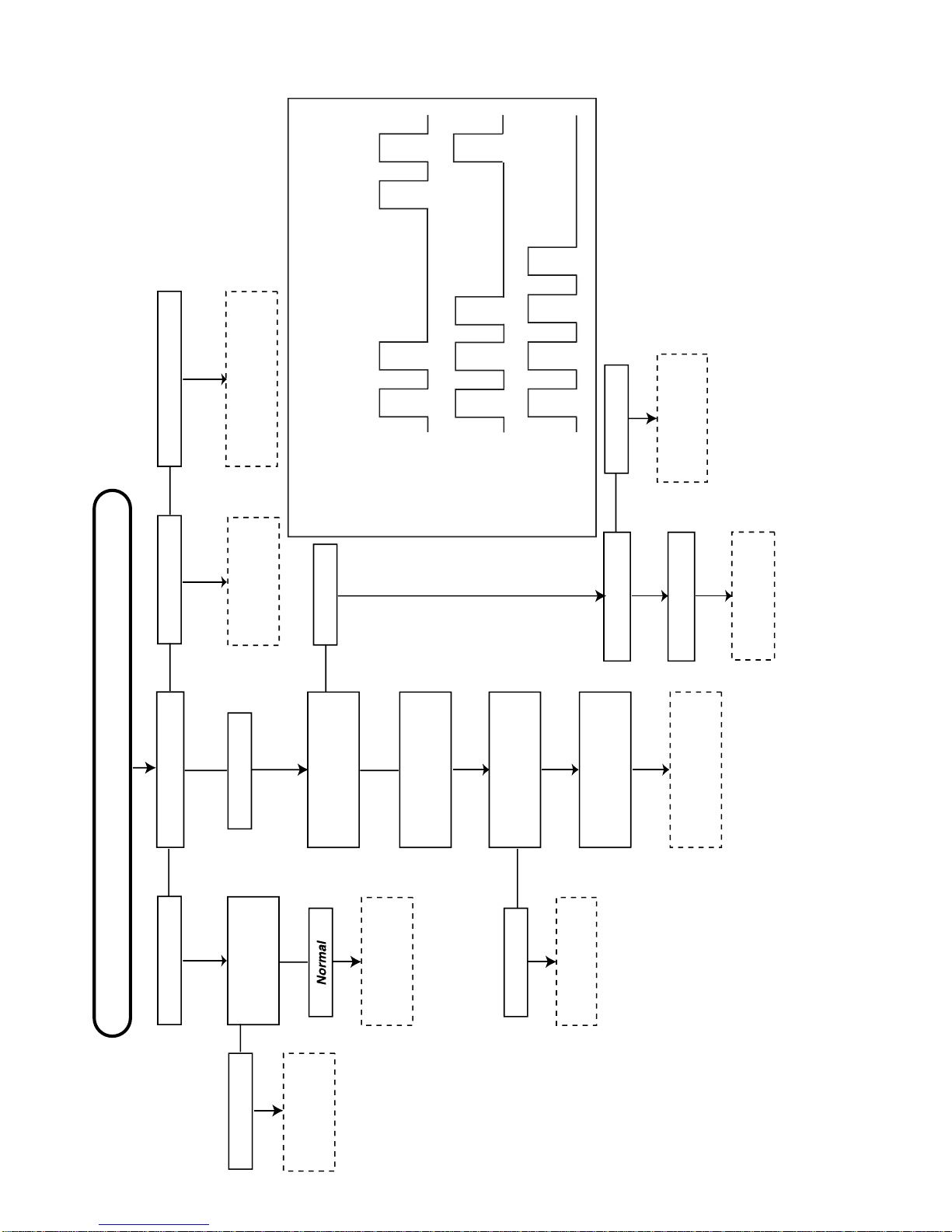
CHECKING FUNCTION OPERATION (TEXT MODE)
NO
1
2
ADJUSTMENT POINT
TEXT
TEXT key
ADJUSTMENT CONDITION / PROCEDURE
(1) Receive E-12ch signal.
(2) Press TEXT key to check changeTEXT mode /
SPLIT SCREEN mode / TELETEXT mode / MIXED
mode.
(1) Receive E-12ch signal.
(2) Press HALF PAGE, HOLD, REVEAL, CLOCK, CANCEL,
LIST, INDEX, and RESET key to check whether each
effect is OK or not.
(3) Select V-SIZE, Press Volume Up/Down key to check
whether the V-SIZE effect is OK or not.
WAVEFORM OR OTHERS
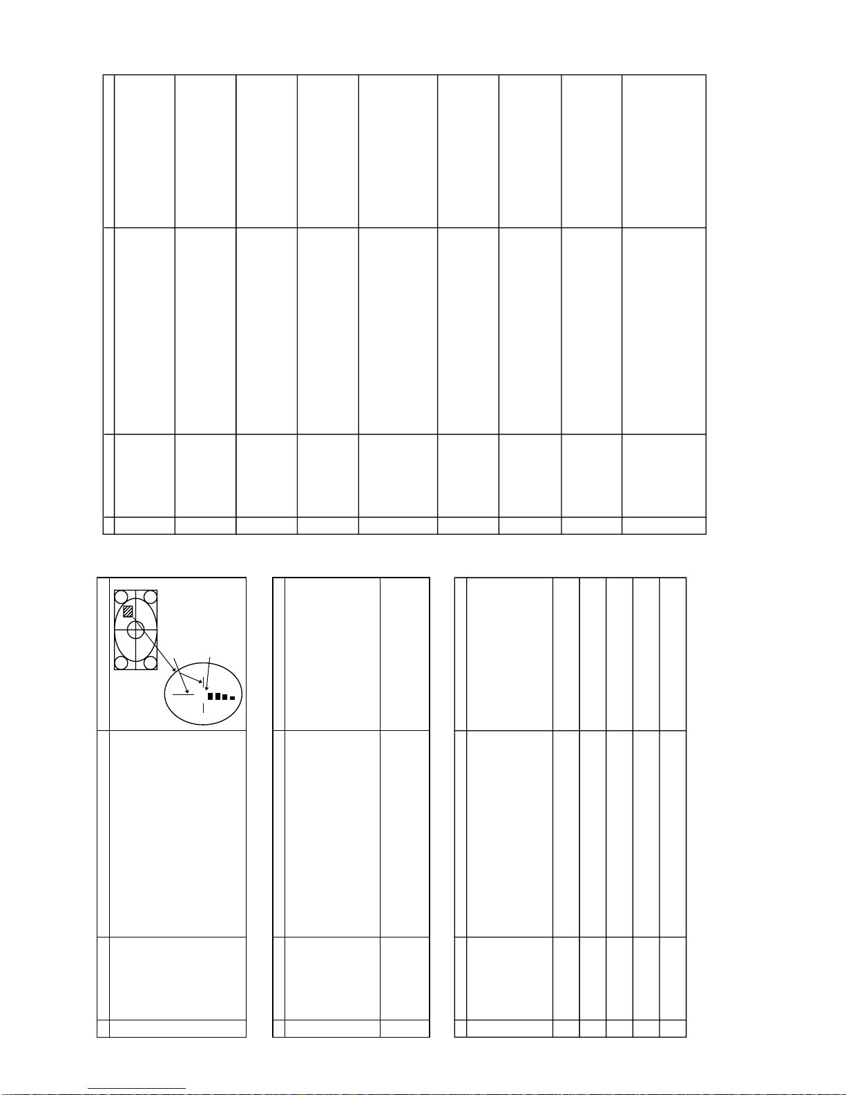
PURITY AND CONVERGENCE ADJUSTMENT
NO
1ADJUSTMENT POINT
DY location (YPB)
adjustment procedure
ADJUSTMENT CONDITION / PROCEDURE
(1) Turn on the set to make coarse adjustments to the CRT
cut-off, white balance, etc.as well as the purity static
convergence.
(2) To improve the purity adjustment accuracy, perform
coarse adjustments to the H-SIZE/center, V-SIZE/LIN
and side pin.
(3) Enter the video mode to set the beam current to the
standard value below using the screenVR.(Or it is
possible to use the noise signal of an empty channel.)
Age the set for more than 30 minutes with the following
current.
Standard value of beam current:1000µA ±200µA
(4) Receive the monoscope signal to adjust the cut-off
voltage.
Consequently, adjust the contrast, color level and then
set the beam current to the above standard value.
Age the set for more than 2 minutes.
Note: If other adjustments between step 3 and 4 (the
area marked by *) affect the conditions of the beam
current, complete the adjustment for each point within 2
minutes, which is not included in the aging time).
* Perform the adjustments in an earth magnetism room
with Bh and Bv set to 0.20G and -0.50G respectively.
(5) Under the above conditions, move DY and the purity
magnet to make the following adjustments.
- 1. SetYPB of DY to 2.5 mm temporarily.
- 2. Adjust the center to A rank by moving the purity
magnet.
- 3. Insert a temporary wedge to balance DY vertically.
- 4. Move DY back and forth to set L and R to the
standard value below.(Apply to the purity correction
magnet if L and R are imbalanced.)
- 5. Correct the center to "AB rank" if the L and R are
imbalanced.
- 6. After making sure the landing is properly positioned,
fix DY.
Note: Preliminary adjustments are made to set L and R
to the standard value after convergence adjustment.
Standard value: -25 µm ±5 µm at the 90 mm point
WAVEFORM OR OTHERS
Purity adjustment
Aging for more
than 2 minutes
Aging for more than 30 minutes
Raster
output
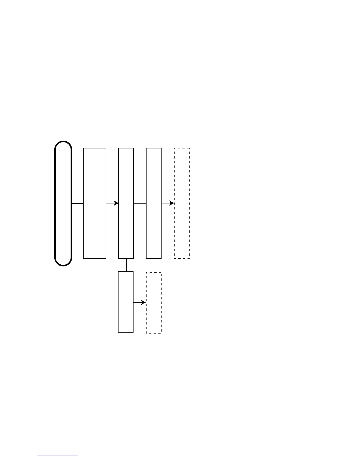
PURITY AND CONVERGENCE ADJUSTMENT (Continued)
NO
2
ADJUSTMENT POINT
Peripheral landing
correction
ADJUSTMENT CONDITION / PROCEDURE
(1) Place the set in a magnetic room with the horizontal line
and vertical line set to 0G and - 0.5G respectively, and
receive red monochrome.
(2) After a complete external; demagnetization, generate a
horizontal magnetic field of ±10000nT (0.1G) and apply
the purity correction magnet to the multi-colored areas.
Check blue monochrome equally.
(3) Return the magnetic field to zero and perform a
complete demagnetization.
(4) Generate a reverse horizontal magnetic field, check red
and blue monochrome and apply the magnet to multi-
colored areas.
(5) After correcting the magnet in step 4, check the reverse
magnetic field again.
3 Directional tolerance
check (1) Place the set in a magnetic room the horizontal line and
vertical line set to 0.2G and - 0.5G respectively, and
receive red monochrome.
(2) Move the set from side to side at the four points of the
compass to check the status of the multiple colors and
ensure L and R are well-balanced.
(3) Apply to the purity correction magnet if L and R are
imbalanced.
(4) If the magnet was applied in step 3, check from other
directions equally.
WAVEFORM OR OTHERS
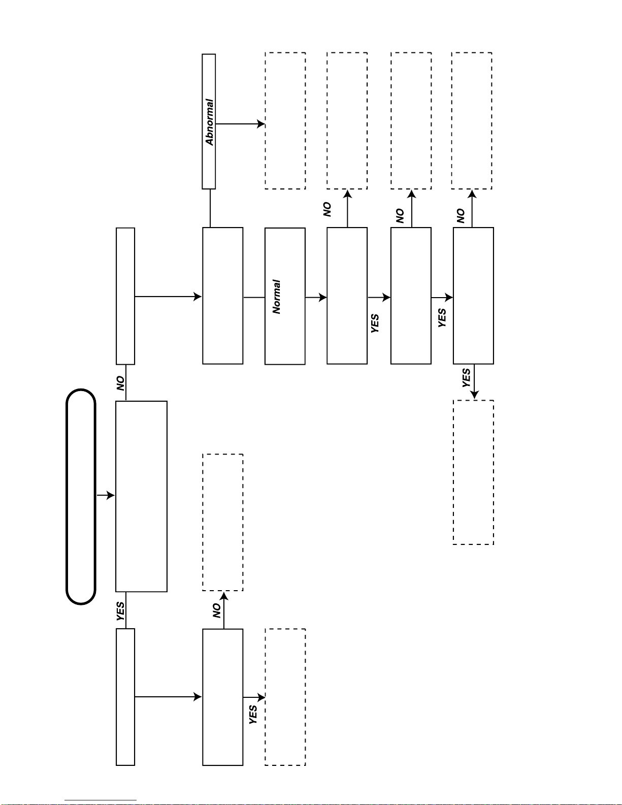
4 Convergence
adjustment procedure (1) Set the video adjustment level to normal, and receive a
crosshatch pattern.
(2) Center convergence adjustment
Superimpose RGB of the screen center area for
optimization, by using the 4 pole and 6 pole of the purity
magnet. Superimpose the red and blue by the 4 pole
magnet, the green and magenta by the 6 pole magnet.
As for vertical lines, avoid setting the red line to the left,
blue to the right.
(3) Peripheral convergence adjustment
Combine the following item with the ferrite sheet to make
optimal adjustments.
1.XV cross
Rotate the variable coil on the DY PWB for
optimization.
2.YH cross
Adjust with the volume on the DY PWB.
If peripheral PQH is oversized, correct with the ferrite
sheet or by shaking slightly.
3.XH,YV
Use the dedicated correction strip to correct them.
YH YV
XV