Sharp 20MU11 User manual

1
20MU11
COLOR TELEVISION
Chassis No. SN-80
In the interests of user-safety (Required by safety regulations in some countries) the set should be restored to its
original condition and only parts identical to those specified should be used.
»ELECTRICAL SPECIFICATIONS......................................................................................................... 1
»IMPORTANT SERVICE SAFETY PRECAUTION ................................................................................. 2
»LOCATION OF USER'S CONTROL..................................................................................................... 6
»INSTALLATIONAND SERVICE INSTRUCTIONS................................................................................7
»CHASSIS LAYOUT ............................................................................................................................ 12
»BLOCK DIAGRAM ............................................................................................................................. 13
»SCHEMATIC DIAGRAMS .................................................................................................................. 14
»PRINTED WIRING BOARD ASSEMBLIES ........................................................................................ 18
»REPLACEMENT PARTS LIST ........................................................................................................... 23
»PACKING OF THE SET ..................................................................................................................... 35
Page
SHARP CORPORATION This document has been published to be used for after
sales service only.
The contents are subject to change without notice.
CONTENTS
SERVICE MANUAL
POWER INPUT ................................ 120 V AC 60 Hz
POWER RATING .............................................82 W
PICTURE SIZE.......................1,194cm2(185sq inch)
CONVERGENCE........................................Magnetic
SWEEP DEFLECTION................................Magnetic
FOCUS...........................Hi-Bi-Potential Electrostatic
INTERMEDIATE FREQUENCIES
Picture IF Carrier Frequency .................45.75 MHz
Sound IF Carrier Frequency .................. 41.25 MHz
Color Sub-Carrier Frequency ................ 42.17 MHz
(Nominal)
ELECTRICAL SPECIFICATIONS
AUDIOPOWER
OUTPUT RATING ...........0.9 W (at 10% distortion)
SPEAKER
SIZE ..................................................8 cm (Round)
VOICE COILIMPEDANCE...........8 ohm at 400 Hz
ANTENNA INPUT IMPEDANCE
VHF/UHF................................ 75 ohm Unbalanced
TUNING RANGES
VHF-Channels.......................................... 2 thru 13
UHF-Channels........................................ 14 thru 69
CATV Channels ...................................... 1 thru 125
(EIA, Channel Plan U.S.A.)
Specifications are subject to change without
prior notice.
MODELS
20MU11

2
IMPORTANT SERVICE SAFETY PRECAUTION
ËService work should be performed only by qualified service technicians who are thoroughly
familiar with all safety checks and the servicing guidelines which follow:
4A 125V
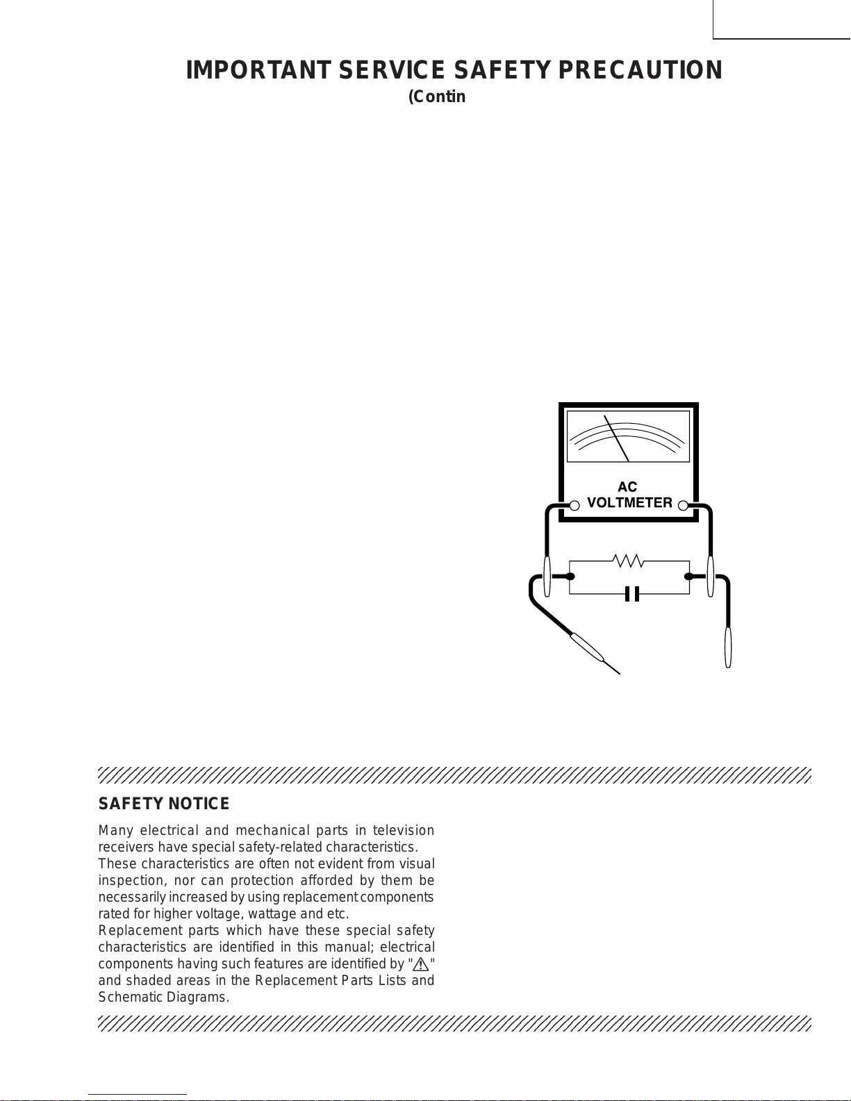
SERVICING OF HIGH VOLTAGE SYSTEM
AND PICTURE TUBE
When servicing the high voltage system,
remove the static charge by connecting a
10k ohm resistor in series with an insulated
wire (such as a test probe) between the pic-
ture tube ground and the anode lead. (AC
line cord should be disconnected from AC
outlet.)
1. Picture tube in this receiver employs integral
implosion protection.
2. Replace with tube of the same type number for
continued safety.
3. Do not lift picture tube by the neck.
4. Handle the picture tube only when wearing
shatterproof goggles and after discharging the high
voltage anode completely.
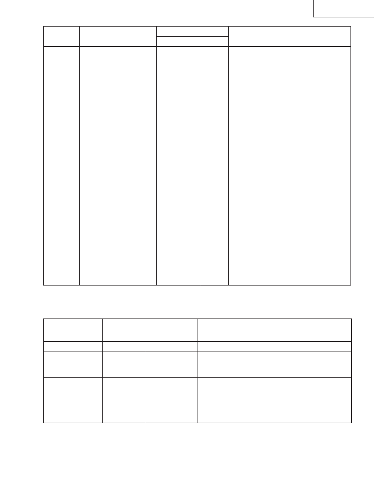
X-RADIATION AND HIGH VOLTAGE LIMITS
1. Be sure all service personnel are aware of the
procedures and instructions covering X-radiation.
The only potential source of X-ray in current solid
state TV receivers is the picture tube. However, the
picture tube does not emit measurable X-Ray
radiation, if the high voltage is as specified in the
"High Voltage Check" instructions.
It is only when high voltage is excessive that X-
radiation is capable of penetrating the shell of the
picture tube including the lead in the glass material.
The important precaution is to keep the high voltage
below the maximum level specified.
2. It is essential that servicemen have available at all
times an accurate high voltage meter.
The calibration of this meter should be checked
periodically.
3. High voltage shouldalways bekeptat therated value
-no higher. Operation at higher voltages may cause
a failure of the picture tube or high voltage circuitry
and;also, under certain conditions, may produce
radiation in exceeding of desirable levels.
4. When the highvoltage regulator isoperating properly
there is no possibility of an X-radiation problem.
Everytime acolor chassisis serviced, the brightness
should be tested while monitoring the high voltage
with a meter to be certain that the high voltage does
notexceedthe specifiedvalueand that itis regulating
correctly.
5. Do not use a picture tube other than that specified
ormake unrecommendedcircuit modifications to the
high voltage circuitry.
6. When troubleshooting andtaking test measurements
onareceiverwith excessive highvoltage,avoidbeing
unnecessarily close to the receiver.
Donot operate the receiver longerthan is necessary
to locate the cause of excessive voltage.
WARNING
1. For continued safety, no modification of any circuit
should be attempted.
2. Disconnect AC power before servicing.
3. Semiconductor heat sinks are potential shock
hazards when the chassis is operating.
4. Thechassis in this receiver hastwo ground systems
whichare separatedby insulatingmaterial.The non-
isolated (hot) ground system is for the B+ voltage
regulatorcircuit andthe horizontaloutput circuit. The
isolatedground systemis for thelow B+DC voltages
and the secondary circuit of the high voltage
transformer.
To prevent electrical shock use an isolation
transformer between the line cord and power
receptacle, when servicing this chassis.
CAUTION: FOR CONTINUED
PROTECTION AGAINST A
RISK OF FIRE, REPLACE
ONLY WITH SAME TYPE 4A-
125V FUSE.
20MU11

3
12345678901234567890123456789012123456789012345678901234567890121234567890123456789012345678901212
1
234567890123456789012345678901212345678901234567890123456789012123456789012345678901234567890121
2
12345678901234567890123456789012123456789012345678901234567890121234567890123456789012345678901212
12345678901234567890123456789012123456789012345678901234567890121234567890123456789012345678901212
1
234567890123456789012345678901212345678901234567890123456789012123456789012345678901234567890121
2
12345678901234567890123456789012123456789012345678901234567890121234567890123456789012345678901212
SAFETY NOTICE
Many electrical and mechanical parts in television
receivers have special safety-related characteristics.
These characteristics are often not evident from visual
inspection, nor can protection afforded by them be
necessarilyincreasedbyusing replacement components
rated for higher voltage, wattage and etc.
Replacement parts which have these special safety
characteristics are identified in this manual; electrical
components having such features are identified by "å"
and shaded areas in the Replacement Parts Lists and
Schematic Diagrams.
IMPORTANT SERVICE SAFETY PRECAUTION
(Continued)
1. Inspect all lead dress to make certain that leads are
not pinched or that hardware is not lodged between
the chassis and other metal parts in the receiver.
2. Inspect all protective devices such as non-metallic
control knobs, insulating materials, cabinet backs,
adjustment and compartment covers or shields,
isolation resistor-capacity networks, mechanical
insulators and etc.
3. To be sure that no shock hazard exists, check for
leakage current in the following manner.
»Plug the AC cord directly into a 120 volt AC outlet,
(Do not use an isolation transformer for this test).
»Using two clip leads, connect a 1.5k ohm, 10 watt
resistor paralleled by a 0.15mF capacitor in series
with all exposed metal cabinet parts and a known
earth ground, such as electrical conduit or electrical
ground connected to earth ground.
»Use anAC voltmeter having with 5000 ohm per volt,
or higher, sensitivity to measure the AC voltage drop
across the resistor.
For continued protection, replacement parts must be
identical to those used in the original circuit. The use of
substitutereplacementpartswhich do nothavethesame
safety characteristics as the factory recommended
replacement parts shown in this service manual, may
create shock, fire, X-radiation or other hazards.
BEFORE RETURNING THE RECEIVER
(Fire & Shock Hazard)
Before returning the receiver to the user, perform
the following safety checks.
»Connectthe resistor connection to allexposed metal
parts having a return to the chassis (antenna, metal
cabinet, screw heads, knobs and control shafts,
escutcheon and etc.) and measure the AC voltage
drop across the resistor.
AII checks must be repeated with the AC ine cord
plug connection reversed. (If necessary, a non-
polarized adapter plug must be used only for the
purpose of completing these check.)
Anycurrent measuredmust notexceed 0.5 milliamp.
Any measurements not within the limits outlined
above indicate of a potential shock hazard and
corrective action must be taken before returning the
instrument to the customer.
1.5k ohm
10W
0.15µF
TEST PROBE
CONNECT TO
KNOWN EARTH
GROUND
TO EXPOSED
METAL PARTS
20MU11

4
LOCATION OF USER'S CONTROL
20MU11

5
CIRCUIT PROTECTION
The receiver is protected by a 4.0A fuse (F701),
mounted on PWB-A, wired into one side of the AC
line input.
X-RADIATION PROTECTOR CIRCUIT TEST
After service has been performed on the horizontal
deflection system, high voltage system, +B system,
test the X-Radiation protection circuit to ascertain
proper operation as follows:
1) Apply 120V AC using a variac transformer for
accurate input voltage.
2) Allow for warm up and adjust all customer controls
for normal picture and sound.
3) Receive a good local channel.
4) Connect a digital voltmeter to TP653 and make sure
that the voltmeter reads 21.3 ±1.5 V.
5) Apply external 28.9V DC at TP653 by using an
external DC supply, TV must be shut off.
6) To reset the protector, unplug theAC cord and make
ashort circuit betweenTP651andTP652.Now make
sure that normal picture appears on the screen.
7) If the operation of the horizontal oscillator does not
stop in step 5, the circuit must be repaired before
the set is returned to the customer.
HIGH VOLTAGE CHECK
High voltage is not adjustable but must be checked
to verify that the receiver is operating within safe
and efficient design limitations as specified checks
should be as follows:
1. Connect an accurate high voltage meter between
ground and anode of picture tube.
2. Operate receiver for at least 15 minutes at 120VAC
line voltage, with a strong air signal or a properly
tuned in test signal.
3. Enter the service mode and select the service
adjustment "S19" and Bus data "01" (Y-mute on).
4. The voltage shouldbeapproximately,26.0kV(atzero
beam).
If a correct reading cannot be obtained, check
circuitry for malfunctioning components. After the
voltage test, make Y-mute off to the normal mode.
INSTALLATION AND SERVICE INSTRUCTIONS
Note: (1)When performing any adjustments to resistor controls and transformers use non-metallic
screwdrivers or TV alignment tools.
(2)Before performing adjustments, the TV set must be on at least 15 minutes.
20MU11

6
Figure A.
S01 02
CHANNEL
SERVICE ADJUSTMENT NUMBER
DATA NUMBER
S01 D:00
For adjustments of this model, the bus data is converted to various analog signals by the D/A converter
circuit.
Note: There are still a few analog adjustments in this series such as focus and master screen voltage.
Follow the steps below whenever the service adjustment is required. See "Table-B" to determine, if serv-
ice adjustments are required.
1. Service mode
Before putting unit into the service mode, check that
customer adjustments are in the normal mode. Use
the reset function in the video adjustment menu to
ensure customer controls are in their proper (reset)
position.
2. Service number selection
Once in the service mode, press the Ch-up or Ch-
down button on the remote controller or at the set.
The service adjustment number will vary in
increments of one, from "S01" to "OP". Select the
item you wish to adjust.
3. Data number selection
Press the Vol-up or down button to adjust the data
number.
To enter the service mode and exit service
mode.
While pressing the Vol-up and Ch-up buttons at the
sametime, plug the AC cord into a wall socket.
Now the TV set is switched on and enters the service
mode.
To exit the service mode, turn the television off by
pressing the power button.
55(085)
20MU11

7
SERVICE
NUMBER DATA ADJUSTMENT CONTENTS
ADJUSTMENT ITEM RANGE
INITIAL VALUE
S01 PICTURE 55 00-7F
S02 TINT 46 00-7F
S03 COLOR 32 00-7F
S04 BRIGHTNESS 40 00-7F
S05 SHARPNESS 28 00-3F Must be set to "24"
S06 VERTICAL PHASE 00 00-07 Must be set to "00" ~ "03"
S07 HORIZONTAL PHASE 12 00-1F
S08 RF-AGC 23 00-3F
S09 VERTICAL AMP 20 00-3F
S10 VCO 2C 00-7F
S11 R CUT-OFF 00 00-FF
S12 G CUT -OFF 00 00-FF
S13 B CUT-OFF 00 00-FF
S14 G GAIN 7F 00-FF
S15 B GAIN 7F 00-FF
S16 TRAP(3.58MHz) 00 00 or 01 Must be set to "00"
S17 BALANCE 20 00-3F Must be set to "20"
S18 C.C.POSITION 17 00-7F
S19 Y-MUTE 00 00,01,03
"00" = NORMAL, "01" = No Y, "03" = No VERTICAL
S20 ENERGY SAVE OFFSET 20 00-3F Must be set to "23"
S21 D.D.E.OFFSET 03 00-1F Must be set to "03"
S22 OSD SETUP 00 00-03 Must be set to "00"
S23 TUNER SETUP 00 00-01 Must be set to "00"
OP OPTION 30 00-FF Must be set to "02"
NECESSARY UNNECESSARY
ADJUSTMENT NOTES
PART REPLACED
IC2001
IC2101 X
CRT X
IC201 X
XData is stored in IC2101.
The adjustment is needed to compensate for characteristics
of parts including IC201.
Holding down both the CH-up/down buttons on the TV set in
the service mode for more than 2 seconds will automatically
write the above initial values into IC2101.
Adjust items related to picture tube only.
Table - A
Holdingdown boththe CH-up/down buttonson theTVset atservice mode for more than2 secondswill automatically
write the above initial values into IC2101.
Table - B
20MU11

8
ËSERVICE ADJUSTMENT
VCO Adjustment
1. Connect a digitalvoltmeter between pin(44) of IC201
and ground.
2. Receive a good local channel.
3. Enter the service mode and select the service
adjustment "S10".
4. Adjust the data so that digital voltmeter reads 2.2V.
5. Adjustment is completed, remove the voltmeter,
return to "normal" mode.
RF AGC Adjustment
1. Receive a good local channel.
2. Enter the service mode and select the service
adjustment "S08".
3. Set the data value to point where no noise or beat
appears.
4. Select another channel to confirm that no noise or
beat appears.
Note 1: You will have to come out of the service
mode to select another channel.
Note 2: Setting the data to "00" will produce a black
raster.
Screen Adjustment
1. Connect a digital voltmeter between TP852 and
TP853 on the CRT Unit.
Note: These test points may not be provided.
Then connect the voltmeter to both ends of
R852 located near Q852 on the foil side.
2. Receive a good local channel.
3. Enter the service mode and select the service
adjustment "S03" and set the data value to "00" to
set the color level to minimum. (Record original data
code under adjustment "S03" before changing) You
may skip this step, if you selected a B/W picture or
monoscope pattern.
4. Select the service adjustment "S19" and adjust the
data value to "01", this turn off the luminance signal
(Y-mute).
5. Select the service adjustment "S04" and adjust data
value to obtain 0.17 volts on the digital voltmeter.
6. Adjust the master screen cotrol until the raster
darkens to the point where raster is barely seen.
7. Adjust the service adjustments "S11" red, "S12"
green and "S13" blue to obtain a good grey scale
with normal whites at low brightness level.
8. Select the service adjustment "S19" and reset data
to"00".Select the serviceadjustment"S03" andreset
data to obtain normal color level.
9. Remove digital voltmeter, and reset the master
screen control to obtain normal brightness range.
White Balance Adjustment
1. Receive a good local channel.
2. Enter the service mode and select the service
adjustment "S03" and set to "00" (minimum
color)(Record original data code under adjustment
"S03" before changing). "S03" does not have to be
adjusted,if you selecteda B/W pictureor monoscope
pattern.
3. Alternately adjust the service adjustment data of
"S14" and "S15" until a good grey scale with normal
whites is obtained.
4. Select the service adjustment "S03" and adjust data
to obtain normal color level.
Sub-Picture Adjustment
1. Receive a good local channel.
2. Make sure the customer picture control is set to
maximum.
3. Enter the service mode and select the service
adjustment "S01".
4. Adjust the data value to achieve normal contrast
range.
Sub-Tint Adjustment
1. Receive a good local channel.
2. Set customer tint control to center of it's range.
3. Enter the service mode and select the service
adjustment "S02".
4. Adjust"S02" data value to obtainnormal fleshtones.
Sub-Color Adjustment
1. Receive a good local channel.
2. Make sure the customer color control is set to center
position .
3. Enter the service mode and select service
adjustment "S03".
4. Adjust "S03" data value to obtain normal color level.
20MU11

9
Sub-Brightness Adjustment
1. Receive a good local channel.
2. Make sure the customer brightness control is set to
center position.
3. Enter the service mode and select the service
adjustment "S04".
4. Adjust "S04" data value to obtain normal brightness
level.
Vertical-Size Adjustment
1. Receive a good local channel.
2. Enter the service mode and select the service
adjustment "S09".
3. While observing the top and bottom of the screen,
adjust "S09" data value to proper vertical size.
Vertical Phase Adjustment
1. Enter the service mode and select the service
adjustment "S06".
2. Adjust data value to "00" ~ "03".
Note: This must be set "00" ~ "03" when changed data
retrace line will appear.
Horizontal Position Adjustment
1. Have unit receive a good local channel.
2. Enter the service mode and select the service
adjustment "S07".
3. Adjust "S07" data value so that picture is centered.
Caption Position Adjustment (Horizontal)
1. Receive a good local channel.
2. Enter the service mode and select the service
adjustment "S18".
3. Ablack text box appears on the screen. (see Figure
B. below)
4. Adjust"S18" data value so thattext boxis positioned
in the center of the screen.
3.58MHz Trap Adjustment
1. Receive a good local channel.
2. Enter the service mode and select the service
adjustment "S16".
3. This is a two position adjustment, "00" is ON, "01" is
OFF.
4. Adjust data value to "00" for normal viewing.
Sharpness, Audio Balance, Energy Save
Offset, DDE Offset, OSD Setup, Tuner
Setup and Option Adjustments
1. Receive a good local channel.
2. Enter the service mode and select the service
adjustments "S05" for sharpness, "S17" for balance,
"S20" for energy save offset, "S21" for DDE offset,
"S22" for OSD setup, "S23" for tuner and "OP" for
option.
»Sharpness Adjustment
3. Adjust data value to "24" (center of data range) for
sharpness adjustment.
»Audio Balance Adjustment
4. Adjust data value to "20" (center of data range) for
audio balance adjustment.
»Energy Save Offset Adjustment
5. Adjust data value to "23".
»DDE Offset Adjustment
6. Adjust data value to "03".
»OSD Setup Adjustment
7. Adjust data value to "00".
»Tuner Setup Adjustment
8. Adjust data value to "00".
»Option Adjustment
9. Adjust data value to "02".
Figure B.
20MU11

10
654321
A
B
C
D
E
F
G
H
CHASSIS LAYOUT
Ë 20MU11
PWB-B
PWB-A
PWB-B
20MU11

11
654321
A
B
C
D
E
F
G
H
BLOCK DIAGRAM
20MU11

12
DESCRIPTION OF SCHEMATIC DIAGRAM
NOTES:
1. The unit of resistance "ohm" is omitted.
(K=k
Ω
=1000
Ω
, M=M
Ω
)
2. All resistors are 1/16 watt, unless otherwise noted.
3. All capacitors are µF, unless otherwise noted.
(P=pF=µµF)
4. (G) indicates ±2% tolerance may be used.
5. indicates line isolated ground.
6. indicates hot ground.
VOLTAGE MEASUREMENT CONDITIONS:
1. All DC voltages are measured with DVM connected
between points indicated and chassis ground, line
voltageset at120VACandall controls setfor normal
picture unless otherwise indicated.
2. All voltages measured with 1000µ V B & W or Color
signal.
WAVEFORM MEASUREMENT CONDITIONS:
1. Photographs taken on a standard gated color bar
signal, the tint setting adjusted for proper color. The
wave shapes at the red, green and blue cathodes of
the picture tube depend on the tint, color level and
picture control.
2.
indicates waveform check points (See chart,
waveforms are measured from point indicated to
chassis ground.)
å
AND SHADED ( ) COMPONENTS
= SAFETY RELATED PARTS.
'
MARK= X-RAY RELATED PARTS.
DRGANNES MARQUES
å
ET HACHRES ( ):
PIECES RELATIVES A LA SECURITE.
MARQUE
'
: PIECS RELATIVE AUX RAYONS X.
This circuit diagram is a standard one, printed
circuits may be subject to change for product
improvement without prior notice.
WAVEFORMS
20MU11

654321
A
B
C
D
E
F
G
H
20MU11
SCHEMATIC DIAGRAM: CRT UNIT
(DUNTK9533WEV4)
(DUNTK9530WEW6)
13

14
20MU11

15
20MU11

16
20MU11

20MU11
17

18
654321
A
B
C
D
E
F
G
H
PRINTED WIRING BOARD ASSEMBLIES
Ë20MU11
PWB-A: MAIN Unit (Wiring Side)
20MU11
(DUNTK9529WEX7)

19
654321
A
B
C
D
E
F
G
H
PWB-A: MAIN Unit (Chip Parts Side)
20MU11

20
654321
A
B
C
D
E
F
G
HË20MU11
PWB-A: MAIN Unit (Wiring Side)
20MU11
PRINTED WIRING BOARD ASSEMBLIES
DUNTK9532WEX0
Table of contents
Other Sharp TV manuals

Sharp
Sharp LC-13S2U, LC-15S2U, LC-20S2U User manual

Sharp
Sharp Aquas LC-52LE920UN User manual

Sharp
Sharp 43BN2EA User manual

Sharp
Sharp CX51K3 User manual

Sharp
Sharp 21HM-10C User manual

Sharp
Sharp LC-26GA5X User manual

Sharp
Sharp SX68K7 User manual

Sharp
Sharp LC32DV24U - 31.5" LCD TV User manual

Sharp
Sharp LC-C4254U - 42" LCD TV User manual

Sharp
Sharp LC-65UI7252K User manual

Sharp
Sharp 51AT-15S User manual

Sharp
Sharp 54GS-61S User manual

Sharp
Sharp Aquos LC-65UB30U User manual

Sharp
Sharp 37GQ-20S User manual

Sharp
Sharp LC-32CHE5100E(W) User manual

Sharp
Sharp 29H-FD5RU User manual

Sharp
Sharp LC-49CUG8052E User manual

Sharp
Sharp 21JF2-GA User manual

Sharp
Sharp AQUOSLC-42GX3H User manual

Sharp
Sharp EQ Series User manual