Sheldon RF2015 User manual

LOW TEMPERATURE
DIURNAL ILLUMINATION
INCUBATOR
MODEL: RF2015
Serial Number: RF02033111
INSTALLATION AND OPERATION MANUAL
REV. 09/10
4861428

TABLE OF CONTENTS
SECTION 1.0 RECEIVING AND INSPECTION
SECTION 2.0 INSTALLATION
SECTION 3.0 GRAPHIC SYMBOLS
SECTION 4.0 CONTROL PANEL OVERVIEW
SECTION 5.0 OPERATION
SECTION 6.0 MAINTENANCE
SECTION 7.0 TROUBLESHOOTING
SECTION 8.0 PARTS LIST
UNIT SPECIFICATIONS
WIRE DIAGRAMS
This unit is a general purpose Diurnal Growth Chamber for professional, industrial
or educational use where the preparation or testing of materials is done at
approximately atmospheric pressure and no flammable, volatile or combustible
materials are being heated. This unit is not intended for hazardous or household
locations or use.

RECEIVING AND INSPECTION
Your satisfaction and safety require a complete understanding of this unit. Read the
instructions thoroughly and be sure operators are given adequate training before
attempting to put the unit into service. This equipment must be used only for its intended
application; any alterations or modifications will void your warranty.
1.1 Inspection: The carrier, when accepting shipment, also accepts responsibility for
safe delivery and is liable for loss or damage. On delivery, inspect for visible exterior
damage, note and describe on the freight bill any damage found, and enter your
claim on the form supplied by the carrier.
1.2 Inspect for concealed loss or damage on the unit itself, both interior and exterior. If
necessary, the carrier will arrange for official inspection to substantiate your claim.
1.3 Return Shipment: Save the shipping crate until you are sure all is well. If for any
reason you must return the unit, first contact your customer representative for
authorization. Supply nameplate data, including model number and serial number.
Please see the manual cover for information on where to contact Customer Service.
1.4 Accessories: Verify that your accessory package is complete. Each unit is
equipped with a key and four (4) shelves.
WARNING: Never use this unit for the growth, cultivation, incubation or storage of fruit
flies (drosophila melanogaster). This unit is not designed for use with fruit flies.
Improper use of this unit, including use with fruit flies, will void any warranty. Other
units are specifically manufactured for fruit fly application, and you should consult your
dealer or the manufacturer in order to identify another model suitable for your
application.
Section
1

INSTALLATION
Local city, county, or other ordinances may govern the use of this equipment. If you have
any questions about local requirements, please contact the appropriate local agency.
Installation may be performed by the end user. It is unnecessary for this unit to be
installed by a technician.
Under normal circumstances this unit is intended for use indoors, at room temperatures
between 18and 28C, at no greater than 80% Relative Humidity ( at 25C ) and with a
supply voltage that does not vary by more than 10%. Customer service should be
contacted for operating conditions outside of these limits.
This unit should remain upright for 24 hours prior to operating. This will allow the oil to
settle in the compressor.
2.1 Power Source: See the incubator's serial/data plate for the voltage, cycle, phase
and ampere requirements. VOLTAGE SHOULD NOT VARY MORE THAN 10%
FROM THE DATA PLATE RATING. These units are intended for 50/60 Hz
application. Electrical supply to the unit must conform to all national and local
electrical codes. A separate circuit is recommended to avoid overloading or failure
of other equipment on the same circuit.
2.2 Location: When selecting a site for the incubator, consider all conditions which
may affect performance, such as extreme heat from steam radiators, stoves,
ovens, autoclaves, etc. Avoid direct sun, fast-moving air currents, heating/cooling
ducts, and high traffic areas. To ensure air circulation around the unit allow a
minimum of 20cm between incubator and any walls or partitions which might
obstruct free air flow.
2.3 Lifting / Handling: These units are heavy and care should be taken to use
appropriate lifting devices that are sufficiently rated for these loads. Units should
only be lifted from their bottom surfaces. Doors, handles and knobs are not
adequate for lifting or stabilization. The unit should be completely restrained from
tipping during lifting or transport. All moving parts, such as shelves and trays
should be removed and doors need to be positively locked in the closed position
during transfer to prevent shifting and damage.
2.4 Leveling: The unit must sit level and solidly. Turn the leveling feet
counterclockwise to raise level. If the unit must be moved, turn the leveling feet in
all the way to prevent bending or damage.
2.5 Cleaning: The incubator's interior was cleaned at the factory, but not sterilizied.
Remove all interior parts, including shelves and clean thoroughly with a disinfectant
that is appropriate for your application. Regular periodic cleaning is required.
Special care should be taken when cleaning around sensing heads to prevent
damage. DO NOT USE chlorine based bleaches as this may damage the
incubator interior. DO NOT USE spray cleaners that might leak through cracks
and openings and get on electrical components, or that may contain solvents that
will harm coatings.
WARNING: Never clean the unit with alcohol or flammable cleaners with the unit
connected to the electrical supply. Always disconnect the unit from the electrical service
Section
2

when cleaning and assure all volatile or flammable cleaners are evaporated and dry
before reattaching the unit to the power supply.

GRAPHIC SYMBOLS
Your incubator is provided with a display of graphic symbols on the control panel
which are designed to help identify the use and function of the adjustable
components.
1. Indicates that you should consult your manual for
further description and discussion of a control or
user item.
2. Indicates “Temperature”
3. Indicates “Overtemperature”
4. C Indicates “Degrees Centigrade”
5. Indicates “AC Power”
6. Indicates “Manual Adjustment”
7. Indicates “Potential Shock Hazard” behind
partition
8. Indicates “Earth Ground”
9. Indicates “Unit should be recycled” (Not disposed
of in land-fill)
Section
3
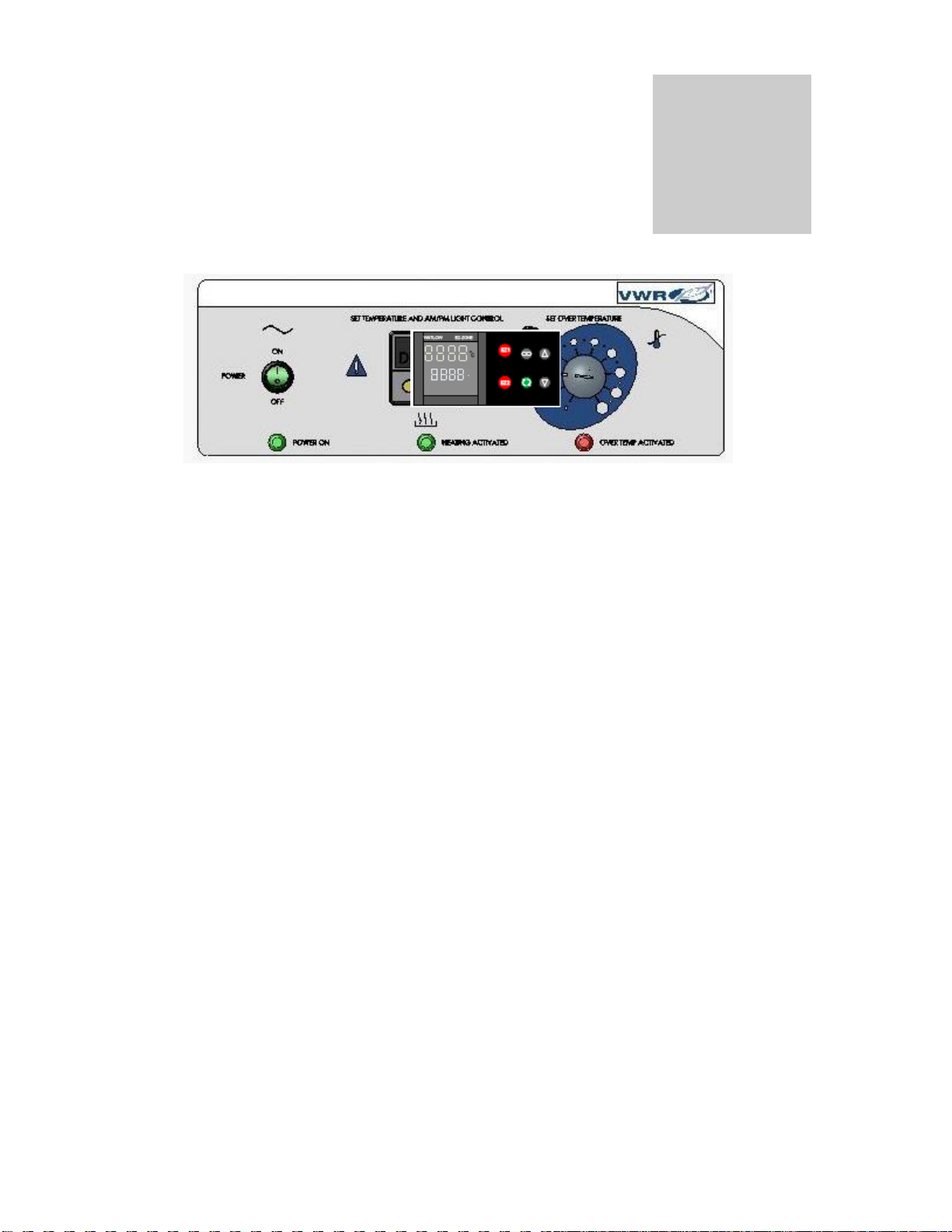
CONTROL PANEL OVERVIEW
The RF2015 comes with one control (Watlow PM) that can be set to do all light and
temperature setting functions. It has an ON/OFF Power Switch to turn the unit On or OFF
and one Over Temperature Protection for High Temperature Limit.
4.1 Power Switch: The main power I/O (on/off) switch controls all power to the unit
and must be in the I/On position before any systems are operational.
4.2 Main Temperature Control: This control is marked SET TEMPERATURE and
AM/PM LIGHT CONTROL. It has two digital displays. Top Display reads
PROCESS TEMPERATURE and bottom display reads SET POINT
TEMPERATURE. The control is a 40-Step Ramp and Soak Programmable Control
with two (2) Event Outputs.
4.3 Over Temperature Thermostat: This control are marked SET OVER
TEMPERATURE and are equipped with adjustment knob and graduated dial.
Completely independent of its Main Controller, the Thermostat guards against any
failure which would allow temperature to rise past the Main Controllers set point. If
temperature rises to the Over Temperature set point, this thermostat takes control of
the heating element and allows continued use of the incubator until the problem can
be resolved or service can be arranged. It is not recommended that the unit be
allowed to operate for an extended period of time using only the Over Temperature
thermostat as temperature uniformity will suffer.
4.4 HEATING Light: Marked HEATING ACTIVATED, this pilot lights indicates when
the Main Controller has activated the heating elements to reach and maintain set
point temperatures.
4.5 OVERTEMP Light: Marked OVERTEMPERATURE ACTIVATED, these pilot lights
indicate when the Over Temperature Thermostat has been activated. Under normal
operating conditions this pilot light should never come on.
4.6 Circuit Breaker: Located on the rear bottom next to the cord inlet provides
protection against power source variations. Protection is in addition to the automatic
high temperature limit designed into the heating element. If the Circuit breaker
opens, the unit will shut down and the cause should be determined and corrected
before resetting the circuit breaker.
Section
4

OPERATION
The refrigeration system, heater, and air circulating fan are used in conjunction with the
temperature control circuit to achieve sensitive temperature control. The temperature
sensor located in the air stream senses any temperature deviation from the control point,
and heat is provided to maintain desired temperature. The circulating fan provides even air
distribution throughout the chamber and assures temperature uniformity.
Regardless of the temperature maintained, the refrigeration system operates continuously.
This constant operation minimizes component failures which are more frequently
associated with a cycling type operation. Note that a factory set Low-Limit Thermostat will
shut off the compressor when temperatures reach around 1C so samples will not freeze.
5.1 Plug incubator into electrical service corresponding to data plate rating located on
the side of the unit. Turn the power switch to the ON position and turn each
Overtemperature Thermostat to its maximum position, clockwise using a coin or
flat edged tool.
5.2 Place a certified reference thermometer (not supplied) in the center of the
chamber. Be certain the thermometer is not touching any shelving or chamber
walls. Taping the thermometer to a petri dish raises it off the shelf and keeps the
scale in view. Placing a reference thermometer in the chamber at this stage of
operation will allow for calibrating the control without the loss of processing time.
5.3 Loading Procedure: Adequate spacing should be allowed between items
whenever possible. Proper spacing will allow maximum air circulation, which is
necessary for temperature uniformity.
5.4 Frost Buildup: Excessive frost buildup on the evaporator coil located on the lower
rear wall can affect temperature uniformity. Liquid containers should never be
placed in the chamber without covers. The evaporation of moisture within the
chamber will only add frost and hasten the need for defrosting. Defrosting
instructions are available in section 6.0, Maintenance.
Section
5

20.0
20.0 EZ1
EZ2
1 2 3
C
ACTUAL PROCESS
TEMPERATURE DISPLAY
PROCESS SETPOINT
DISPLAY
INDICATES OUTPUT 1 ACTIVE
HEATING ELEMENT ON
INDICATES OUTPUT 2 ACTIVE
LIGHTS ON
INDICATES OUTPUT 3 ACTIVE
LIGHT CALIBRATION OFFSET ON
RAMPING SYMBOL
INDICATES PROGRAM
RUNNING WHEN ACTIVE ADVANCE KEY
ALLOWS TO SCROLL
THROUGH PARAMETER LIST
DOWN ARROW KEY
ALLOWS TO LOWER SETPOINT
OR CHANGE PARAMETERS
UP ARROW KEY
ALLOWS TO RAISE SETPOINT
OR CHANGE PARAMETERS
INFANITE KEY
ALLOWS TO BACK UP
ONE LEVEL OR RETURN
TO HOME PAGE
EASY ZONE KEY 1
STARTS AND STOPS
PROGRAM
CONTROLLER KEYS AND DISPLAYS
5.5 Set Temperature Control and AM/PM Light Control: The control comes from the
factory with a 12-hour day and a 12 hour night cycle alreadyprogrammed into the contol. To
run the program, choose the Set Point that you desire by using the UP or DOWN Arrow
Keys. (Bottom Display Set Point and Top Display Process). Once Set Point has been
entered, push the EZ1 Button and the program will start. The Program is set up to run the
day cycle first. To stop the program, push the EZ1 Button again. (Note: When stopping the
program, the control will remain in the condition that it is previously in.)
To restart the program, push the EZ1 Button again. (Note: The 12 Hour Day Cycle always
starts first and begins when the program is started.) Day cycle is running with Indicator 2
and 3-Ramp Symbol is illuminated.
5.6 Controller Programming Overview: The controller is capable of programming four
(4) different files with ten (10) different steps in each file or one (1) file with forty(40) different
steps. The 12-hour day/12-hour night cycle using one Set Point uses one (1) file with four
(4) steps. The second step run the 12-hour day cycle. After the 12-hour timer counts down,
it automatically switches to Step 3 which runs the night cycle. After the 12-hour timer counts
down, it automatically switches to Step 4. Step 4 tells the program to return to Step 2 and
the process starts all over. Step 1 is an unused step reserved for Specific Time activation.
Before a Specific Time activation time is entered, the Real Time Clock must be set for the
real time. Next are instructions on “How To Set The Real Time Clock” and “How To Enter A
Program at Specific Time.”
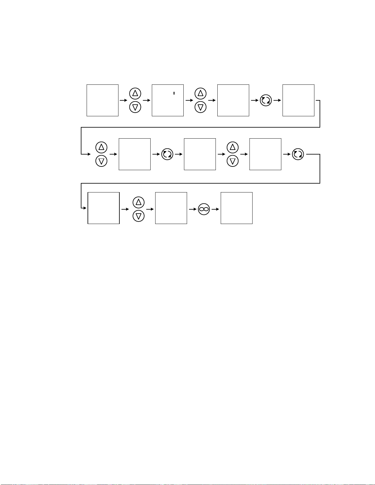
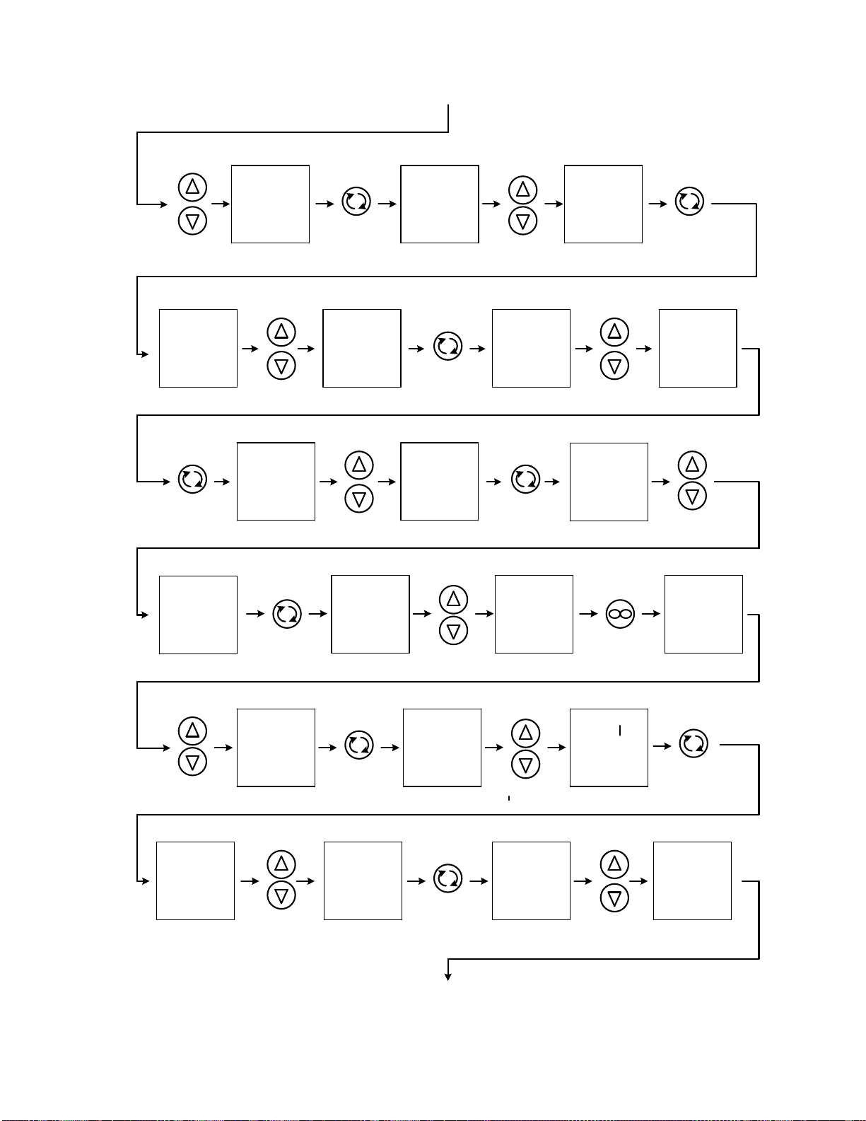
SETTING THE REAL TIME CLOCK
20.0
20.0 SEt
ArtC
SEt hoUr
Min
dOW
hoUr
HOUR OF DAY
Min
MINUTES OF
HOUR
dOW 20.0
20.0
PUSH AND HOLD
FOR 6 SECONDS
OR UNTIL NEXT
SCREEN APPEARS
PUSH UP OR
DOWN ARROWS
TO SELECT
rtC IN UPPER
DISPLAY
PUSH ONCE
FOR NEXT
BOTTOM
DISPLAY
SCREEN
PUSH UP OR
DOWN ARROWS
TO SELECT HOUR
OF DAY IN UPPER
DISPLAY
PUSH ONCE
FOR NEXT
BOTTOM
DISPLAY
SCREEN
PUSH UP OR
DOWN ARROWS
TO SELECT
MINUTES OF
HOUR IN UPPER DISPLAY
PUSH ONCE
FOR NEXT
BOTTOM
DISPLAY
SCREEN
PUSH UP OR
DOWN ARROWS
TO SELECT THE
DAY OF THE WEEK
IN THE UPPER DISPLAY
PUSH TWICE
TO RETURN
NORMAL
DISPLAY
MODE
DAY OF WEEK
BELOW IS INSTRUCTION ON HOW TO SET THE REAL
TIME CLOCK IN THE WATLOW PM CONTROL
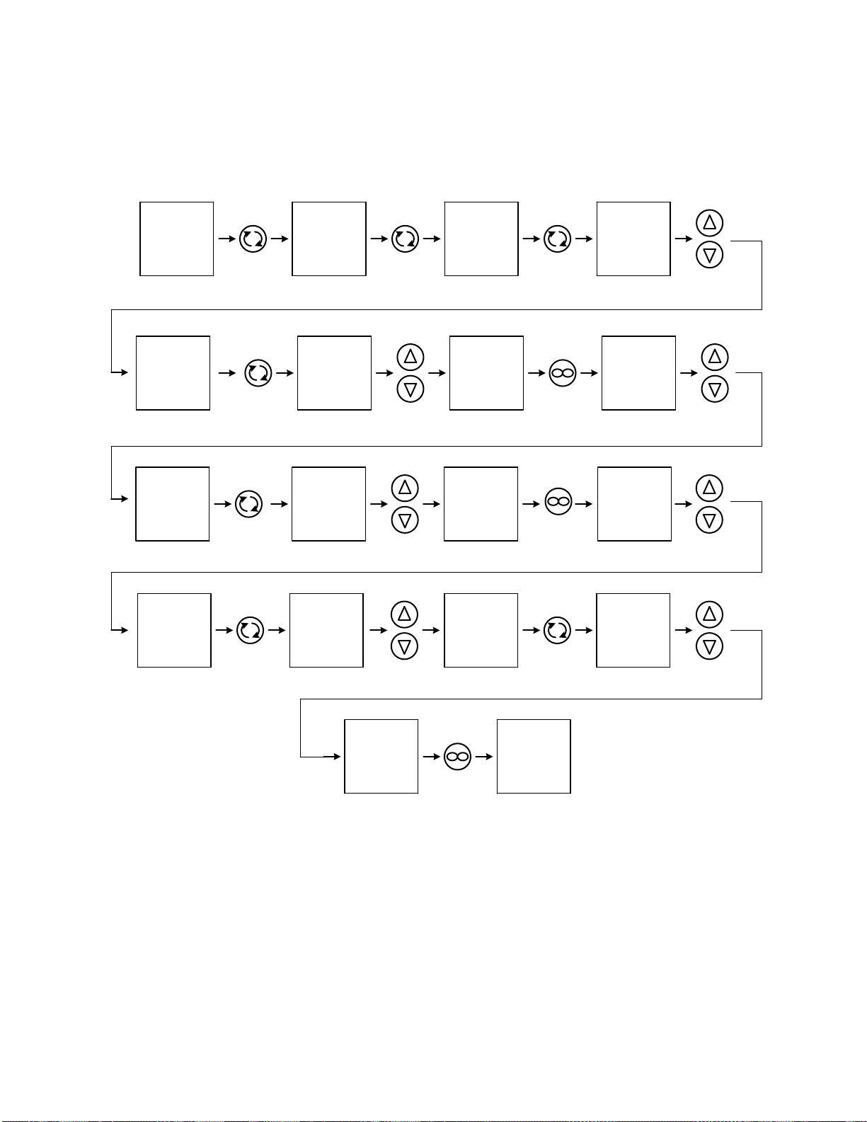
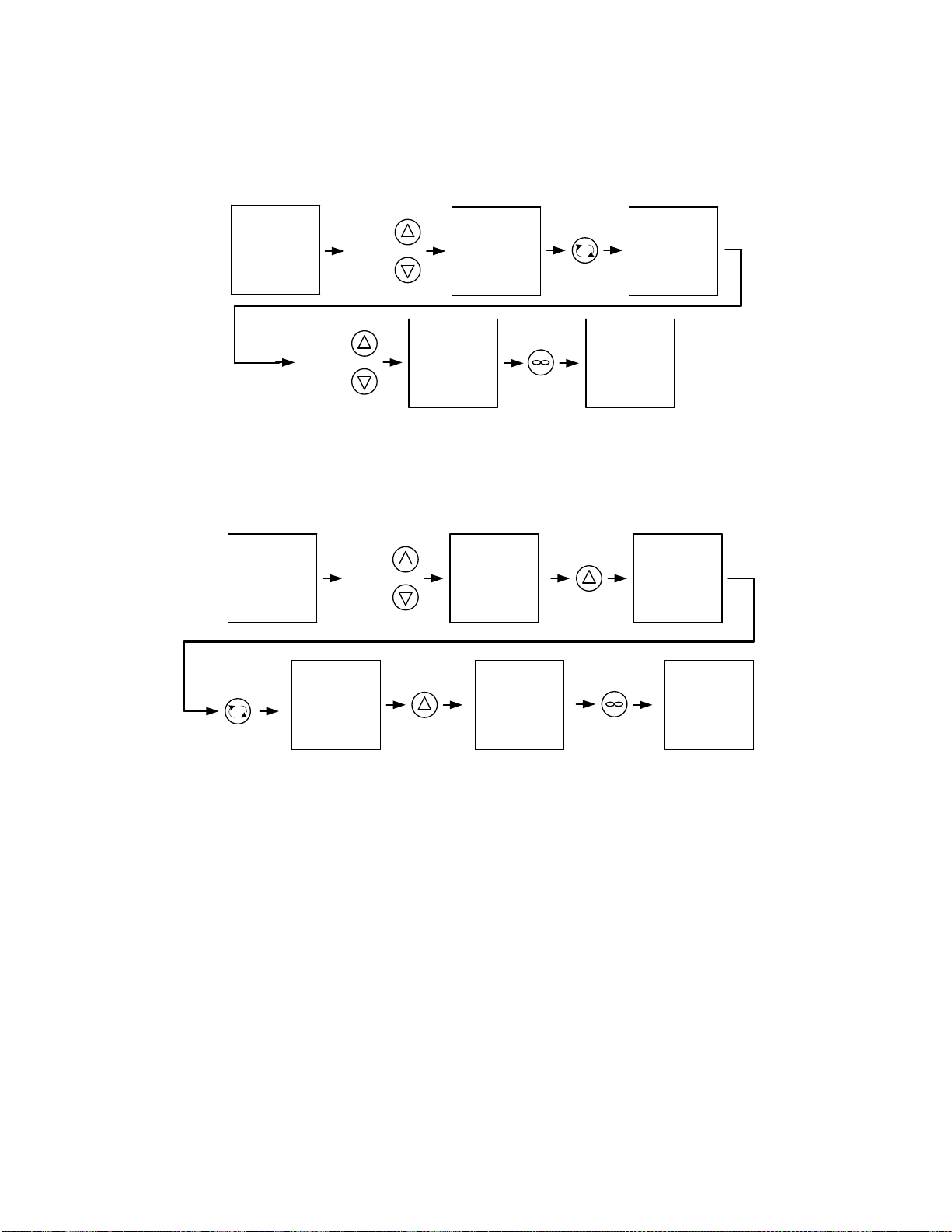
STARTING PROGRAM AT A SPECIFIC TIME
THE PM CONTROL CAN BE PROGRAMED TO START THE 12 HOUR DAY AND 12 HOUR NIGHT CYCLE AT A
SPECIFIC TIME OF DAY. THE PROGRAMING PARAMETERS NEED TO BE ENTERED IN PROFILE 1 STEP 1 IN
THE CONTROL. THE S.TYP NEEDS TO BE SET FOR CLoC AND THEN CHOOSE WHAT HOUR, MINUTE, AND
SECOND OF THE DAY, AND WHAT DAY OF THE WEEK FOR THE PROGRAM TO START. BELOW IS INSTUCTION
ON H0W TO ENTER THE PARAMETERS
20.0
20.0 P1
ProF 1
P1 S.tyP
hoUr Min
0
SEC
S.tyP hoUr
Min SEC
Ent 1
ON OR OFF
Ent 1 Ent 2
ON OR OFF
Ent 2 20.0
20.0
PUSH AND HOLD
FOR 3 SECONDS
OR UNTIL NEXT
SCREEN APPEARS
PUSH ONCE
FOR NEXT
SCREEN
PUSH ONCE
FOR NEXT
SCREEN
PUSH ONCE
FOR NEXT
SCREEN
USE UP OR
DOWN ARROWS
TO CHANGE
UPPER DISPLAY
TO CLoC
CLoC PUSH ONCE
FOR NEXT
SCREEN
USE UP OR
DOWN ARROWS
TO CHANGE
UPPER DISPLAY
TO HOUR OF DAY
PUSH ONCE
FOR NEXT
SCREEN
USE UP OR
DOWN ARROWS
TO CHANGE
UPPER DISPLAY
TO MINUTE OF HOUR
HOUR OF DAY
MINUTE OF HOUR PUSH ONCE
FOR NEXT
SCREEN
USE UP OR
DOWN ARROWS
TO CHANGE
UPPER DISPLAY
TO SECOND OF MINUTES
PUSH ONCE
FOR NEXT
SCREEN
dOW
USE UP OR
DOWN ARROWS
TO CHANGE
UPPER DISPLAY
TO DAY OF WEEK
DAY OF WEEK
dOW
PUSH ONCE
FOR NEXT
SCREEN
USE UP OR
DOWN ARROWS
TO CHANGE UPPER
DISPLAY TO DAY OR NIGHT
OFF=NIGHT DAY=ON
TO CHANGE UPPER
DISPLAY TO DAY OR NIGHT
OFF=NIGHT DAY=ON
USE UP OR
DOWN ARROWS
PUSH THREE
TO RETURN TO
NORMAL DISPLAY
AFTER THE PARAMETERS HAVE BEEN ENTERED PUSH THE EZI PUTTON TO START THE TIMING. THE RAMP
SYMBOL WILL ALLUMINATE ON THE RIGHT OF THE DISPLAY TO INDICATE THE PROGRAM IS RUNNING. WHEN THE
TIME AND DAY THAT WAS SELECTED IS REACHED THE 12 HOUR DAY AND 12 HOUR NIGHT CYCLE WILL START.
NOTE: CHOOSING DAY OR HIGHT UNDER THE ENT PARAMETER WILL RUN
THAT SETTING UNTIL THE 12 HOUR DAY AND 12 HOUR NIGHT CYCLE STARTS.

12-HOUR DAY AND 12-HOUR NIGHT CYCLE WITH ONE SET POINT
TEMPERATURE PROGRAMMING INSTRUCTIONS
20.0
20.0 P1
ProF 1
P1 S.tyP
S.tyP
UStP
hoUr hoUr
12
Min Min
0SEC
SEC
0Ent 1 on
Ent 1 Ent 2
on
Ent 2 3
P1
2
P1
S.tyP
SoAh
PUSH AND
HOLD FOR
3 SECONDS
UNTIL NEXT
SCREEN
APPEARS
PUSH ONCE
FOR NEXT
DISPLAY
SCREEN
USE UP
OR DOWN
ARROWS
TO SELECT
UStP IN TOP
DISPLAY
PUSH ONCE
FOR NEXT
BOTTOM
DISPLAY
SCREEN
USE UP
OR DOWN
ARROWS
TO SELECT
2 IN TOP
DISPLAY
PUSH ONCE
FOR NEXT
BOTTOM
DISPLAY
SCREEN
PUSH ONCE
FOR NEXT
BOTTOM
PUSH ONCE
FOR NEXT
BOTTOM
DISPLAY
SCREEN
TO SELECT
S.tyP IN TOP
DISPLAY
USE UP
OR DOWN
ARROWS
TO SELECT
12 IN TOP
DISPLAY
PUSH ONCE
FOR NEXT
BOTTOM
DISPLAY
SCREEN
PUSH ONCE
FOR NEXT
BOTTOM
USE UP
OR DOWN
ARROWS
USE UP
OR DOWN
ARROWS
TO SELECT
0 IN TOP
DISPLAY
DISPLAY
SCREEN
USE UP
OR DOWN
ARROWS
TO SELECT
0 IN TOP
DISPLAY
PUSH ONCE
TO RETURN
PREVIOUS
SCREEN
USE UP
OR DOWN
ARROWS
TO SELECT
on IN TOP
DISPLAY
PUSH ONCE
FOR NEXT
BOTTOM
DISPLAY
SCREEN
USE UP
OR DOWN
ARROWS
TO SELECT
on IN TOP
DISPLAY
PUSH ONCE
FOR NEXT
BOTTOM
DISPLAY
SCREEN
USE UP
OR DOWN
ARROWS
TO SELECT
3 IN TOP
DISPLAY
NEXT PAGE
PUSH ONCE
TO RETURN
PREVIOUS
SCREEN
1
P1 2
P1
S.tyP
DISPLAY
SCREEN

Min Min
0SEC
SEC
0
Ent 1 oFF
Ent 1 Ent 2
oFF
Ent 2 3
P1
S.tyP S.tyP
JL JS JS
2
JC JC
0Ent 1
oFF
Ent 1 Ent 2 oFF
Ent 2 20.0
20.0
PUSH ONCE
FOR NEXT
BOTTOM
USE UP
OR DOWN
ARROWS
TO SELECT
SoAh IN TOP
DISPLAY
DISPLAY
SCREEN
USE UP
OR DOWN
ARROWS
TO SELECT
12 IN TOP
DISPLAY
PUSH ONCE
FOR NEXT
BOTTOM
DISPLAY
SCREEN
USE UP
OR DOWN
ARROWS
TO SELECT
0 IN TOP
DISPLAY
PUSH ONCE
FOR NEXT
BOTTOM
DISPLAY
SCREEN
USE UP
OR DOWN
ARROWS
TO SELECT
oFF IN TOP
DISPLAY
PUSH ONCE
TO RETURN
PREVIOUS
SCREEN
USE UP
OR DOWN
ARROWS
TO SELECT
oFF IN TOP
DISPLAY
PUSH ONCE
FOR NEXT
BOTTOM
DISPLAY
SCREEN
USE UP
OR DOWN
ARROWS
TO SELECT
oFF IN TOP
DISPLAY
PUSH ONCE
FOR NEXT
BOTTOM
DISPLAY
SCREEN
USE UP
OR DOWN
ARROWS
TO SELECT
4 IN TOP
DISPLAY
PUSH ONCE
FOR NEXT
BOTTOM
DISPLAY
SCREEN
USE UP
OR DOWN
ARROWS
TO SELECT
JL IN TOP
DISPLAY
PUSH ONCE
FOR NEXT
BOTTOM
DISPLAY
SCREEN
USE UP
OR DOWN
ARROWS
TO SELECT
2 IN TOP
DISPLAY
PUSH ONCE
FOR NEXT
BOTTOM
DISPLAY
SCREEN
USE UP
OR DOWN
ARROWS
TO SELECT
0 IN TOP
DISPLAY
PUSH TWICE
TO RETURN
NORMAL
DISPLAY
MODE
PUSH ONCE
FOR NEXT
BOTTOM
DISPLAY
SCREEN
S.tyP S.tyP
SoAh hoUr hoUr
12
USE UP
OR DOWN
ARROWS
TO SELECT
0 IN TOP
DISPLAY
4
P1
PUSH ONCE
FOR NEXT
BOTTOM
DISPLAY
SCREEN
USE UP
OR DOWN
ARROWS
TO SELECT
oFF IN TOP
DISPLAY

To change the Time Variations in the Day and Night Cycle, change the Time Parameters
in P1 Step 2 and P1 Step 3. P1 Step 2 is set up for Day Cycle and P1 Step 3 is set up for
Night Cycle. Changing the amount of time affects the Run Time of the Step.
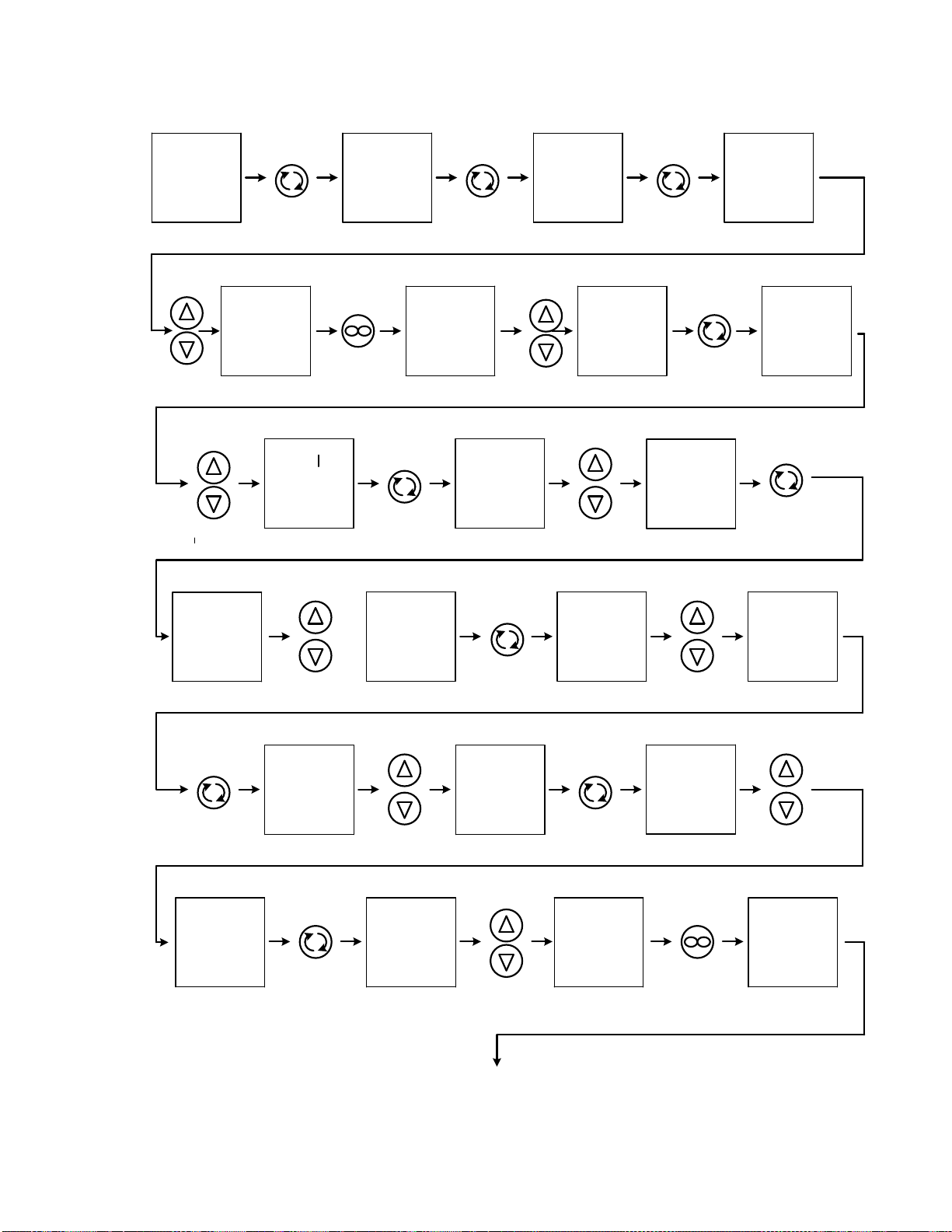
PROGRAMMING CONTROL TO RUN 12-HOUR DAY AND
12-HOUR NIGHT CYCLE AT TWO DIFFERENT SET POINTS
The Watlow PM can also be programmed to run at different Set Point Temperatures. The
following drawing “How To Enter The Parameters To Run A 12-Hour Day Cycle And 12-
Hour Night Cycle At Two Different Set Point Temperatures.”
This program uses one (1) file and six (6) different Steps:
Step 1: Is an unused Step and is reserved for starting the program at Specific Time.
Step 2: Parameters are for entering the Set Point for the Day Cycle. (This Step uses
one (1) second of time.)
Step 3: Parameters are how long the Day Cycle will run at Set Point from Step 2.
Step 4: Parameters are entering the Set Point for the Night Cycle. (This Step also uses
one (1) second of time.)
Step 5: Parameters are how long the Night Cycle will run at Set Point from Step 4.
Step 6: Parameters are repeating the cycle (Jump-Looping) back to Step 2.
NOTE: Changing the amount of time in Step 3 and Step 5 also allows different time cycles in the
Day and Night Cycle, if desired.
20.0
20.0 P1
ProF 1
P1 S.tyP
PUSH AND
HOLD FOR
5 SECONDS
UNTIL NEXT
SCREEN
APPEARS
PUSH ONCE
FOR NEXT
DISPLAY
SCREEN
PUSH ONCE
FOR NEXT
BOTTOM
DISPLAY
SCREEN
S.tyP
UStP 1
P1 2
P1 S.tyP
PUSH ONCE
FOR NEXT
BOTTOM
DISPLAY
SCREEN
PUSH ONCE
TO RETURN
PREVIOUS
SCREEN
USE UP
OR DOWN
ARROWS
TO SELECT
2 IN TOP
DISPLAY
S.tyP
tt.SPl
hoUr
0Min Min
0
Ent 1
on
Ent 1
USE UP
OR DOWN
ARROWS
TO SELECT
t IN TOP
DISPLAY
PUSH ONCE
FOR NEXT
BOTTOM
DISPLAY
SCREEN
USE UP
OR DOWN
ARROWS
TO SELECT
DESIRED SET
POINT IN TOP DISPLAY
PUSH ONCE
FOR NEXT
BOTTOM
DISPLAY
SCREEN
PUSH ONCE
FOR NEXT
BOTTOM
DISPLAY
SCREEN
TO SELECT
0 IN TOP
DISPLAY
USE UP
OR DOWN
ARROWS
TO SELECT
0 IN TOP
DISPLAY
PUSH ONCE
FOR NEXT
BOTTOM
DISPLAY
SCREEN
PUSH ONCE
FOR NEXT
BOTTOM
USE UP
OR DOWN
ARROWS
USE UP
OR DOWN
ARROWS
TO SELECT
1 IN TOP
DISPLAY
DISPLAY
SCREEN
USE UP
OR DOWN
ARROWS
TO SELECT
On IN TOP
DISPLAY
USE UP
OR DOWN
ARROWS
TO SELECT
on IN TOP
DISPLAY
t.SPl
SET POINT
VALUE SET POINT
VALUE
hoUr
SEC SEC
1
Ent 2
PUSH ONCE
FOR NEXT
BOTTOM
DISPLAY
SCREEN
on
Ent 2
PUSH ONCE
TO RETURN
PREVIOUS
SCREEN
2
P1
USE UP
OR DOWN
ARROWS
TO SELECT
UStP IN TOP
DISPLAY
NEXT PAGE
USE UP
OR DOWN
ARROWS PUSH ONCE
FOR NEXT
BOTTOM
DISPLAY
SCREEN
USE UP
OR DOWN
ARROWS PUSH ONCE
FOR NEXT
BOTTOM
DISPLAY
SCREEN
TO SELECT
3 IN TOP
DISPLAY
3
P1 S.tyP
TO SELECT
SoAh IN TOP
DISPLAY
S.tyP
SoAh
Ent 1
on
Ent 1
PUSH ONCE
FOR NEXT
BOTTOM
USE UP
OR DOWN
ARROWS
TO SELECT
11 IN TOP
DISPLAY
DISPLAY
SCREEN
USE UP
OR DOWN
ARROWS
TO SELECT
59 IN TOP
DISPLAY
PUSH ONCE
FOR NEXT
BOTTOM
DISPLAY
SCREEN
USE UP
OR DOWN
ARROWS
TO SELECT
59 IN TOP
DISPLAY
PUSH ONCE
FOR NEXT
BOTTOM
DISPLAY
SCREEN
USE UP
OR DOWN
ARROWS
TO SELECT
on IN TOP
DISPLAY
USE UP
OR DOWN
ARROWS PUSH ONCE
FOR NEXT
BOTTOM
DISPLAY
SCREEN
USE UP
OR DOWN
ARROWS
TO SELECT
0 IN TOP
DISPLAY
hoUr hoUr
11 Min Min
59
SEC SEC
59
USE UP
OR DOWN
ARROWS
TO SELECT
on IN TOP
DISPLAY
Ent 2
PUSH ONCE
FOR NEXT
BOTTOM
DISPLAY
SCREEN
on
Ent 2
PUSH ONCE
TO RETURN
PREVIOUS
SCREEN
3
P1
4
P1 S.tyP
USE UP
OR DOWN
ARROWS
TO SELECT
4 IN TOP
DISPLAY
PUSH ONCE
FOR NEXT
BOTTOM
DISPLAY
SCREEN
USE UP
OR DOWN
ARROWS
S.tyP
t
TO SELECT
t IN TOP
DISPLAY
DISPLAY
SCREEN
PUSH ONCE
FOR NEXT
BOTTOM
TO SELECT
DESIRED SET
POINT IN TOP DISPLAY
t.SPl
SET POINT
VALUE t.SPl
SET POINT
VALUE hoUr hoUr
0
NEXT PAGE

PUSH ONCE
FOR NEXT
BOTTOM
DISPLAY
SCREEN
USE UP
OR DOWN
ARROWS
TO SELECT
0 IN TOP
DISPLAY
Min Min
0SEC
PUSH ONCE
FOR NEXT
BOTTOM
DISPLAY
SCREEN
USE UP
OR DOWN
ARROWS
TO SELECT
1 IN TOP
DISPLAY
oFF
Ent 1 Ent 2
oFF
Ent 2 4
P1 5
P1
USE UP
OR DOWN
ARROWS
TO SELECT
oFF IN TOP
DISPLAY
PUSH ONCE
FOR NEXT
BOTTOM
DISPLAY
SCREEN
USE UP
OR DOWN
ARROWS
TO SELECT
5 IN TOP
DISPLAY
PUSH ONCE
FOR NEXT
BOTTOM
DISPLAY
SCREEN
SEC
1PUSH ONCE
FOR NEXT
BOTTOM
DISPLAY
SCREEN
Ent 1
USE UP
OR DOWN
ARROWS
TO SELECT
oFF IN TOP
DISPLAY
PUSH ONCE
TO RETURN
PREVIOUS
SCREEN
S.tyP
USE UP
OR DOWN
ARROWS
TO SELECT
SoAh IN TOP
DISPLAY
S.tyP
SoAh PUSH ONCE
FOR NEXT
BOTTOM
DISPLAY
SCREEN
hoUr
USE UP
OR DOWN
ARROWS
TO SELECT
11 IN TOP
DISPLAY
hoUr
11
PUSH ONCE
FOR NEXT
BOTTOM
DISPLAY
SCREEN
Min
USE UP
OR DOWN
ARROWS
TO SELECT
59 IN TOP
DISPLAY
Min
59
PUSH ONCE
FOR NEXT
BOTTOM
DISPLAY
SCREEN
SEC
USE UP
OR DOWN
ARROWS
TO SELECT
59 IN TOP
DISPLAY
SEC
59
PUSH ONCE
FOR NEXT
BOTTOM
DISPLAY
SCREEN
Ent 1
USE UP
OR DOWN
ARROWS
TO SELECT
oFF IN TOP
DISPLAY
oFF
Ent 1
PUSH ONCE
FOR NEXT
BOTTOM
DISPLAY
SCREEN
Ent 2
NEXT PAGE

oFF
Ent 2
USE UP
OR DOWN
ARROWS
TO SELECT
oFF IN TOP
DISPLAY
PUSH ONCE
TO RETURN
PREVIOUS
SCREEN
5
P1
USE UP
OR DOWN
ARROWS
TO SELECT
6 IN TOP
DISPLAY
6
P1
PUSH ONCE
FOR NEXT
BOTTOM
DISPLAY
SCREEN
S.tyP
USE UP
OR DOWN
ARROWS
TO SELECT
JL IN TOP
DISPLAY
PUSH ONCE
FOR NEXT
BOTTOM
DISPLAY
SCREEN
USE UP
OR DOWN
ARROWS
TO SELECT
2 IN TOP
DISPLAY
PUSH ONCE
FOR NEXT
BOTTOM
DISPLAY
SCREEN
USE UP
OR DOWN
ARROWS
TO SELECT
0 IN TOP
DISPLAY
PUSH ONCE
FOR NEXT
BOTTOM
DISPLAY
SCREEN
USE UP
OR DOWN
ARROWS
TO SELECT
oFF IN TOP
DISPLAY
S.tyP
JL JS JS
2
JC JC
0Ent 1
oFF
Ent 1
PUSH ONCE
FOR NEXT
BOTTOM
DISPLAY
SCREEN
Ent 2 oFF
Ent 2
USE UP
OR DOWN
ARROWS
TO SELECT
oFF IN TOP
DISPLAY
PUSH TWICE
TO RETURN
NORMAL
DISPLAY
MODE
20.0
20.0

CALIBRATION OFFSET FOR DAY CYCLE
BEFORE CALIBRATION IS MADE MAKE SURE THAT INDICATOR 2, 3, AND RAMP SYMBOL ARE ON INDICATING DAY CYCLE
ACTIVE. FIGURE OUT # VALUE OF OFFSET (ACTUAL TEMPERATURE MINUS PROCESS DISPLAY TEMPERATURE).
BELOW SHOWS WHERE AND HOW TO ENTER THE OFFSET # VALUE.
20.0
20.0
PUSH
AND
HOLD
FOR
5
SECONDS
PUSH
THREE
TIMES
i.CA
# VALUE
USE
UP AND
DOWN
BUTTONS
TO
ENTER
CALIBRATION
# VALUE
i.CA
# VALUE PUSH
TWICE 20.0
20.0
TO RETURN
TO NORMAL
DISPLAY
A1
oPEr OR UNTIL
SCREEN
APPEARS
AFTER THE OFFSET HAS BEEN ENTERED ALLOW UNIT TO STABALIZE. RECHECK TEMPERATURE AGAIN
AND IF CALIBRATION IS WITHIN EXCEPTABLE LIMITS THE OFFSET # VALUE NEEDS TO BE STORED INTO
MEMERY OR IT WILL REVERT BACK TO THE LAST # VALUE ON THE NEXT SWITCHING CYCLE.
BELOW SHOWS HOW TO STORE OFFSET # VALUE FOR THE DAY CYCLE
A1
SET
20.0
20.0
PUSH
AND
HOLD
FOR
10
SECONDS
PUSH
THREE
TIMES LbL
g
SET
PUSH
FOURTEEN
TIMES
OR UNTIL
SCREEN
APPEARS
nonE
Usr.S Usr.S
SET 2
PUSH
ONCE PUSH
TWICE 20.0
20.0
TO RETURN
TO NORMAL
DISPLAY
SELECTING SET 2 UNDER Usr.S SAVES THE OFFSET CALIBRATION FOR THE DAY CYCLE.
CALIBRATION OFFSET FOR NIGHT CYCLE
AFTER THE OFFSET HAS BEEN ENTERED ALLOW UNIT TO STABALIZE. RECHECK TEMPERATURE AGAIN
AND IF CALIBRATION IS WITHIN EXCEPTABLE LIMITS THE OFFSET # VALUE NEEDS TO BE STORED INTO
MEMERY OR IT WILL REVERT BACK TO THE LAST # VALUE ON THE NEXT SWITCHING CYCLE.
BELOW SHOWS HOW TO STORE OFFSET # VALUE FOR THE NIGHT CYCLE
A1
SET
20.0
20.0
PUSH
AND
HOLD
FOR
10
SECONDS
PUSH
THREE
TIMES LbL
g
SET
PUSH
FOURTEEN
TIMES
OR UNTIL
SCREEN
APPEARS
nonE
Usr.S Usr.S
SET 1
PUSH
ONCE PUSH
TWICE 20.0
20.0
TO RETURN
TO NORMAL
DISPLAY
SELECTING SET 1 UNDER Usr.S SAVES THE OFFSET CALIBRATION FOR THE NIGHT CYCLE.
BEFORE CALIBRATION IS MADE MAKE SURE THAT INDICATOR 2, 3, AND RAMP SYMBOL ARE OFF INDICATING NIGHT
CYCLE ACTIVE. FIGURE OUT # VALUE OF OFFSET (ACTUAL TEMPERATURE MINUS PROCESS DISPLAY TEMPERATURE).
BELOW SHOWS WHERE AND HOW TO ENTER THE OFFSET # VALUE.
20.0
20.0
PUSH
AND
HOLD
FOR
5
SECONDS
PUSH
THREE
TIMES
i.CA
# VALUE
USE
UP AND
DOWN
BUTTONS
TO
ENTER
CALIBRATION
# VALUE
i.CA
# VALUE PUSH
TWICE 20.0
20.0
TO RETURN
TO NORMAL
DISPLAY
A1
oPEr OR UNTIL
SCREEN
APPEARS
This manual suits for next models
1
Table of contents
Other Sheldon Accessories manuals


