dacell DN511A User manual

Digital Weighing Indicator
Operating Manual
Model : DN511A
DACELL CO.,LTD
TEL : +82-43-260-2242
FAX : +82-43-260-2242
WEBSITE: http://www.dacell.com
EMAIL : info@dacell.com

CONTENTS
1. Before Installation ---------------------------------- 2 Page
2. Introduction ---------------------------------- 3 Page
3. Specification ---------------------------------- 4 Page
4. Installation ---------------------------------- 10 Page
5. Set-Up ---------------------------------- 12 Page
6. Interface ---------------------------------- 34 Page
7. Error and Treatment ---------------------------------- 46 Page
1/ 49

1. BEFORE INSTALLATION
1-1. Caution / Warning Marks
This mark warns the possibility to arrive death or serious injury in
case of wrongly used.
This mark cautions the possibility to arrive serious human body
injury or product lose in case of wrongly used.
1-2. Other Marks
Warning for Electric Shock or Damage.
Please do not touch by hand
Protective Ground(Earth) terminal
Prohibition of Operation process
1-3. Copy Rights
1). All Right and Authority for this Manual is belonged to DACELL Co., Ltd.
2). Any kinds of copy or distribution without DACELL CO., Ltd’s permission will be prohibited.
1-4. Inquiries
If you have any kinds of inquiries for this model, please contact with your local agent or Head
Office.
Head Office : DACELL co.,Ltd.
Website : http://www.dacell.com
Email : info@dacell.com
Warning
Caution
2/ 49

2. INTRODUCTION
2-1. Introduction
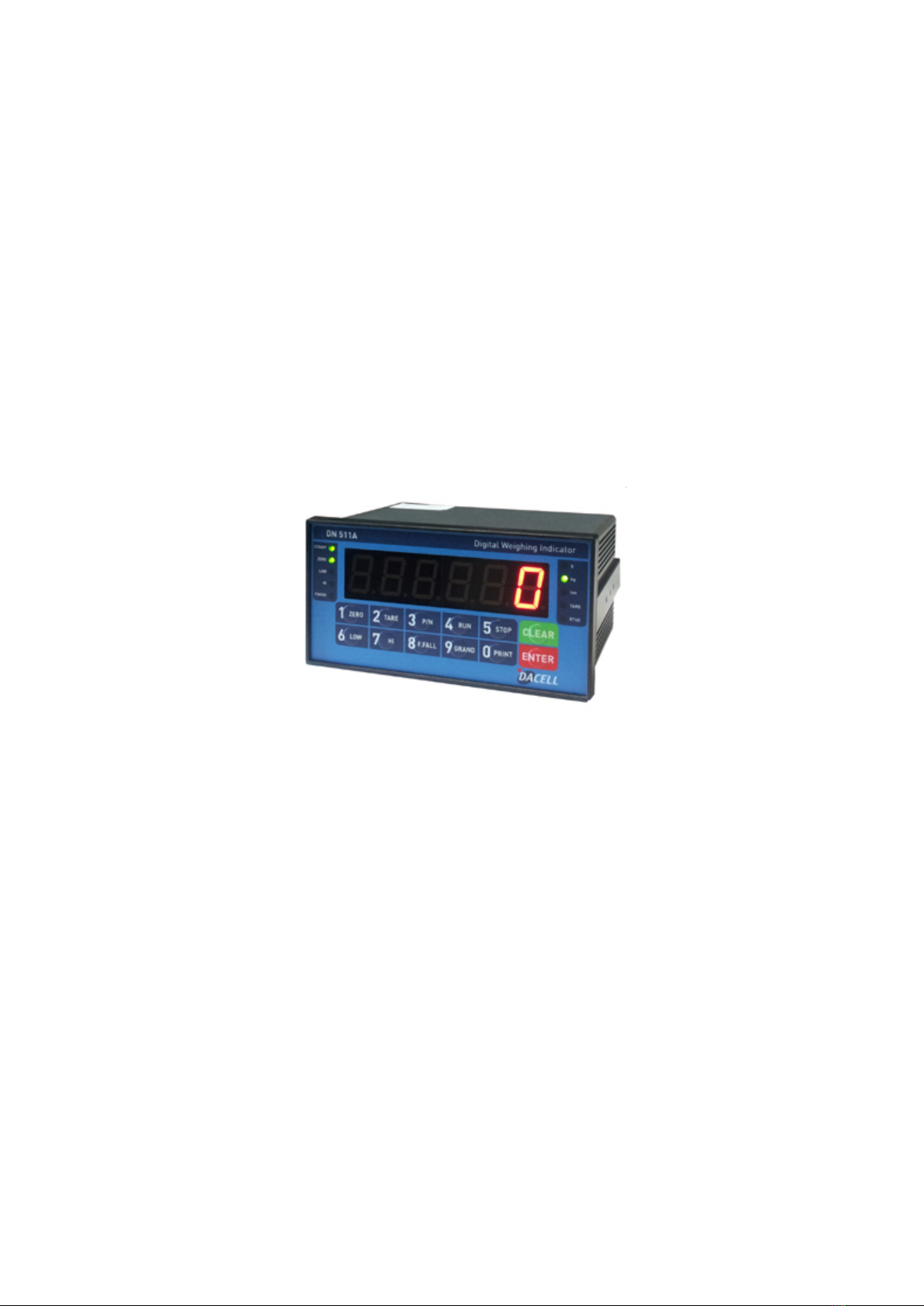
Thank you for your choice, this “DN511A” Industrial Digital Weighing Indictor..
This “DN511A” model is control purpose application usage Digital Weighing Indicator, with
powerful communication performance.
With 4pcs control relay outputs and High Speed A/D conversion performance will lead you to
precise weighing process.
This “DN511A” Weighing Indicator is control purpose application model, and it can be used for
most kinds of control applications.
Please review this instruction Manual and learn more about information about “DN511A”.
Enjoy your process efficiency with “DN511A” Weighing Indicator..
2-2. Cautions
1). Don’t drop on the ground or avoid serious external damage on item.
2). Don’t install under sunshine or heavy vibrated condition.
3). Don’t install place where high voltage or heavy electric noise condition.
4). When you connect with other devices, please turn off the power of item.
5). Avoid from water damage.
6). For the improvement of function or performance, we can change item specification without
prior notice or permission.
7). Item’s performance will be up-dated continuously base on previous version’s performance.
8) The quantity of load cell to connect is max. 6pcs.
2-3. Features
1). All Modules and Option Cards are isolated to maximize accuracy and performance.
2). External input terminal inside.
3). By using “Photo-Coupler” on each module(Option, Analog board, In/Out), we improved
“Impedance problem”, “Isolation ability among inputs”, “Leading power problem”, and
“Noise covering function”.
4). Data back-up function, when the sudden power off
5). Polycarbonate film panel, strong against dust and water
6). RS-232C (Com. Port1) is standard installed.
8). Variable options(Order in advance)
2-4. Box Contents
1). Power Cable(1pcs) / Fuse(2pcs) / Load cell Connector(1pcs) / Manual(1pcs)
Cautions
!
3/ 49

3. SPECIFICATION
3-1. Analog Input &A/D Conversion
Input Sensitivity 0.45㎶/ Digit
Load Cell Excitation
DC 10V ( - 5V ~ + 5V )
Max. Signal Input Voltage
Max.32mV
Temperature Coefficient
[Zero] ±20PPM/℃
[Span] ±20PPM/℃
Input Noise ±0.6㎶P.P
Input Impedance Over 10㏁
A/D Conversion Method
Sigma-Delta
A/D Resolution(Internal)
260,000 Count(18bit)
A/D Sampling Rate
Max. 80times / Sec
Non-Linearity
0.01% FS
Display Resolution(External)
1/30,000
3-2. Digital Part
Display Parts Specification
Display
Main Display 7Segments, 6digits 1.0 inch Red color FND
Size :25.4(H) ×14.4(W)mm
Min. Division
×1, ×2, ×5, ×10, ×20, ×50
Max. display value +999,950
Under Zero value "-" (Minus display)
Status lamp Steady, Zero,
Low, High,
OK(Finish), g, kg, ton, Tare,
RTxD
Green color Condition display Lamp (10pcs)
K e y Number, Function Key Number Key, Function (12pcs)
4/ 49

3-3. General Specification
Power Supply
Trans type Power Supply, AC110/220V
(DIP S/W Selectable)
Operating Temperature Range -10℃~ 40℃
Operating Humidity Range
Under 85% Rh (non-condensing)
External Dimension 193mm(W)x100mm(H)x140mm(L)
Net Weight(kg)
About 2.5kg
Gross Weight(kg)
About 3.0kg
3-4. Option Card
Option No.1
Analogue Output (0~10V)
Option No.2
Analogue Output (4~20mA)
Option No.3
Serial Interface : RS422 / RS485
Option No.4
Option No.5
※Serial Interface (RS-232C) or Current Loop is Standard installed.
And this DN511A indicator can’t use a BCD IN and OUT card.
3-5. Front Panel (Display & Key pad)
5/ 49

3-5-1. Status Lamp (ANNUNCIATORS) : Green Color Lamp is “ON”.
Steady When the weight is Steady, Lamp is turn on.
Zero When the current weight is Zero, Lamp is turn on.
(Displayed weight is Zero, Lamp is turn on.)
Low When weight value reaches to LOW set value, Lamp is turn on.
Hi When weight value reaches to HI set value, Lamp is turn on.
OK(Finish) When the weighing process is Finished, Lamp is turn on.
g When “F40-01” setting, Lamp is turn on.
Kg When “F40-00” setting, Lamp is turn on.
ton When “F40-02” setting, Lamp is turn on.
Tare Tare function is set, Lamp is turn on.
(Tare Reset Lamp is turn off.)
RTxd When indicator transfers or receives data from other devices, Lamp is turn
on. (If the Lamp
is off although there is some data transference, please
check communication settings).
3-5-2. Key Pad Function
Make Weight value as Zero.
Under F08, you can set the Zero key operation range, as 2%, 5%,
10%, 20% or 100% of Max. Capacity.
※
Under “Tare” key input, Zero key will not be activate within
operation range.
Make Weight value as Zero, including Tare Weight.
Under F09, you ca
n set the Tare key operation range, as 10%,
20%, 50%, or 100% of Max. Capacity.
※
Whenever pressing “Tare” key, you can set the Tare
continuously.
You can set each weighing process as a certain P/N.
And you can call certain P/N with pressing this key.
P/N save : Select P/N and Enter key input.
P/N call : P/N + Number key + Enter
6/ 49

Start Weighing process, under Packer Mode, only.
Stop weighing process, under Packer Mode, only.
Set the LOW value or Check the current value.
- Press key and enter new set value with keypad, and press enter
to save.
Set the HI value or Check the current value.
- Press key and enter new set value with keypad, and press enter
to save.
Set the Free Fall value for the High set value..
Free Fall Check : No. 8 key and if press Clear key
it will be
back..
Free Fall Change : No. 8 key + Number key + Enter
Under Print installation, you can print out the “Grand-
total data” of
all P/N.
Printed Data : Accumulated count and weight of All P/N.
Manual Printer
- Key input, print output.
Calibration mode
- Digit setting
Whenever pressing “0”key, digit will be change 1, 2, 5, 10, and 50.
1. Modify the set value during setting process.
2. Calibration mode
- Move back to previous step.
3. F-function setting mode
- Change F-function No.
F-function no.(number key) + Clear directly move
1. Save set value during setting process.
2. Calibration mode
- Save current setting and move to next step.
3. F-Function mode
- Save current F-function setting, and move to next F-function
7/ 49

※Function Keys (Combined Key functions : key + other keys)
For combined key function, you should press “CLEAR” or “ENTER” + other key within 2 sec.
Time set value check or Change
Date set value check or Change
Code value check or Change
Serial No. check or change
Sub-total Print
Sub-total Data Delete
Grand-total Data Delete
Tare Reset
Set “Key Tare” function
8/ 49

3-6. Rear Panel
①POWER -Power ON/OFF Switch
-Fuse : AC 250V 2A
- AC IN : AC110/220V selectable through DIP switch
②OPTION 1,2 - OPTION BOARD install slot.
- ANALOG out, Serial I/F, etc
③LOAD CELL
CONNECTOR (N-16)
-EXC + (+5V) PIN1 (RED)
-EXC - (-5V) PIN2 (WHITE)
-SIG+ PIN3 (BLACK or BLUE)
-SIG-PIN4 (GREEN)
-SHIELD PIN5 (SHEILD)
④Digital Input
- Digital Input Signal terminal
Refer to “F-function 11”.
⑤Relay Output
4pcs Relay output terminal
- According to “F21-XX” setting, relay will be output.
⑥Output Terminal
-RS-232C / CURRENT LOOP / PRT (Standard Installed)
( RXD,TXD,GND,CL1,CL2,PTXD,PGND)
①
②
③
⑤
①
④
⑥
9/ 49

4. INSTALLATION
4-1. External Dimension & Cutting Size
(External Dimension) (unit : mm)
Cutting Size
10 / 49

4-2. Formula to plan the precise weighing system
This “DN511A” weighing controller’s Max. input sensitivity is 0.45
㎶
/ Digit.
And for precise weighing system, the following formula must be satisfied.
Caution : “Input sensitivity” means Min. output voltage variation of weighing part to change
1digit. So, please do not make large input voltage to make reliable weighing system.
Single Load cell use
dEⅹBⅹD A : Load cell capacity(kg)
B : Load cell Voltage(mV)
D : Digit
E : affirmation Voltage of Load cell
N : Number of Load cell
0.45
㎶
A
Plural Load cells use
dEⅹBⅹD
0.45
㎶
AⅹN
Example1.)
Number of Load cell : 1pcs
Load cell capacity : 500kg
Load cell Voltage : 2mV/V
Digit : 0.05kg
Affirmation Voltage of Load cell : 5.0V
Max. Capacity of Weighing System : 300kg
Then, estimation result for this weighing system with formula,
5000ⅹ2ⅹ0.05 = 1 e 0.45㎶The calculated value is larger than 0.45
㎶
,
so this system has no problem.
500
Example2.)
Number of Load cell : 4pcs
Load cell capacity : 500kg
Load cell Voltage : 2mV/V
Digit : 0.10kg
Affirmation Voltage of Load cell : 5.0V
Max. Capacity of Weighing System : 1,000kg
Then, estimation result for this weighing system with formula,
5000ⅹ2ⅹ0.10 = 0.5 e 0.45㎶
The calculated value is larger than
0.45㎶, so this system has no problem.
500ⅹ4
Cautions
!
11 / 49

Chapter 5. Set Up
5-1. Calibration
Adjust weight balance between “Real weight” on the load cell(Weight Part) and “Displayed weight of
Indicator”. When you replace LOAD CELL or Indicator, you have to do Calibration process once again
5-2. Test Weight Calibration (span Calibration) – Mode 1.
- Applicable model : DN500 series
Prepare at least 10% of Max. capacity of your weighing scale.
Step 1. Enter Calibration Mode
Press key during 5 sec display.
Or turn on the Power + with pressing display
Press key display
Press key to start “Calibration Mode”.
Remarks : Go to next step with save key / Back to previous step key
Step 2. Multi-Calibration setting with 4 Section ( display)
P _1 : Section number of Multi-calibration setting
Function : Calibration Section setting for Multi calibration
Set value
(1~4)
Display
Explanation
P 1 You can divide a weight setting from 1 to 4 Section
with max weight.
2-1. If a real curve of load cell is straight line, the calibration section would be 1.
2-2. The multi calibration function is for compensate to load cell’s output by so using a multi-point at
some section when the real curve of load cell is not straight line as like under picture.
P_1
SET-CAL
TEST
SET-CAL
12 / 49

2-3. Under display, if press a keypad No. 2, it will be change the section 2.
And, if press a keypad No. 3 or 4 or 1, it will be change the section 3 or 4 or 1.
Then press key, and move to next step.”
2-4. It would be repeat Step 6~7 when progressing over than 2times to the multi calibration.
So, when progress over than 2times of section calibration, for example if you want some calibration to
set 40kg and prepared Test weight as 1kg and 3kg at Step 6, you should input & up-load a 1kg at first
time then you should input & up-load a 3kg when return to Step 6 again.
Step 3. Digit(Division)setting ( display)
Press key and stop the optimal Digit value.
(Whenever pressing key, digit value will be changed, like 01-02-05-10-20-50)
Press key and save change and move to next step.
Step 4. Max. Capacity Setting (
display)
P_1
XXXXXX
CAPA
d _1
13 / 49

Input Max. Capacity of Scale with No. keys.
Input Capacity and press key, and move to next step.
※
Caution
(Max. capacity value / division value) cannot be over 30,000.(as Indicator resolution is 1/30,000).
Step 5. Zero Balance setting ( display)
Make empty the scale part, and press key.
Indicator check the current Zero balance and save the value and move next step.
Step 6. Span value calculation (
)
Input prepared Test weight value with No. keys.
And press key.
Then, display will show and then, load prepared test weight unit on the scale.
After a few seconds(to remove the vibration effect), press key.
Then, indicator will calculate Span value and move the next step.
※
Caution
For the precise Span calibration, please prepare Test weight unit, at least 10% of Max. capacity
of Scale.
Step 7. Check Span Value and Finish the Calibration( )
Check the Calculated Span value.
And after 3sec, will displayed automatically and move to weighing Mode.
C-END
C-END
XXXXXX
C_UP_
C_UP_
XXXXX
SPAN
CAL _0_
14 / 49

5-3. Simulation Calibration Mode (Without Test Weight) – Mode 2.
- This calibration Method will be useful to make calibration more than 10ton capacity setting.
- Guaranteed resolution will be 1/5,000 and if you need higher resolution, please make
calibration with Test weight.
Step 1. Enter to the “SET-CAL” mode
Press key during 5 sec display.
Or turn on the Power + with pressing display
Press key display.
Press key to start “Simulation Calibration Mode”.
Remarks : Go to next step with save key / Back to previous step key Step 2.
Step 2. Digit (Division)setting ( display)
Press key and stop the optimal Digit value.
(Whenever pressing key, digit value will be changed, like 01-02-05-10-20-50)
Press key and save change and move to next step.
d _ 1
CAL_ _2
SET-CAL
TEST
SET-CAL
15 / 49

Step 3. Max. Capacity of Load cell (
display)
Input Max. Capacity of Scale with No. keys.
- Under this step, input Total sum of each load cell’s Max. Capacity. (Not weighing Scale)
- The Max. Capacity of load cell is stated on “Test report” or “Label”.
- If you installed 4 load cells, and each load cell’s Max. Capacity is 500kg, then you have to input
2,000kg, as a Max. Capacity.
Input Capacity and press key, and move to next step.
Step 4. Measure/Adjustment optimal Zero balance of Scale ( display)
Make empty the scale part, and press key.
Indicator check the current Zero balance and save the value and move next step.
CAL _0_
XXXXXX
CAPA
16 / 49

Step 5. Input Max. Output Rate (mV/V) value of load cell
Input Max. Output Rate(mV/V) value of load cell with No. keys.
- Under this step, input Max. Output rate(mV) of load cell.
- If you installed a few pieces of load cells, the connection will be parallel, so the rated output of
a few load cells are as same as single load cell’s rated output.
- The Output rate is stated on “Test report” or “Label”
And press key.
Step 6. End Calibration and Auto Reset
- Calculated Span value will be displayed and automatically reset and move the normal
weight indicating mode.
17 / 49

5-4. Function Setting – Mode 1.
- Applicable model : DN500 series
To make more accuracy performance of Digital Weighing Indicator, through this Function setting.
Step 1. Enter to Function setting mode.
Turn on the Power + with pressing display
Press key display
Press key to start “F-function Mode”.
Step 2. Change the F-Function No.
To change the F-function No., press key. whenever pressing key, Function No. will
be changed
If you want to move certain function No. directly, press function No. with keypad and press
key.
Step 3. Change the Set value.
Input new set value with keypad, and press key to save new setting.
If you don’t press key, after changing the set value, the new set value will not be saved.
Step 4. Exit from Function setting mode.
Press + + key to exit function mode.
SET-CAL
TEST
18 / 49

5-5. Function List
Function
No. Contents Remark
F01 Decimal point setting Setting range : 0~3
F02 Back up mode selection Setting range : 0, 1
F03 Motion Band setting Setting range : 0~9
F04 Zero Tracking setting Setting range : 0~9
F05 Auto Zero Range setting Setting range : 00~99
F06 Digital Filter setting Setting range : 00~49
F07 Zero / Tare key activating setting Setting range : 0, 1
F08 Zero key operating range setting Setting range : 0~4
F09 Tare key operating range setting Setting range : 0~3
F11 Digital Input setting Setting range : 0~2
F21 Weighing Mode Selection Setting range : 1~4
F22 Weighing Finish Relay “ON” delay time setting Setting range : 0.0~9.9sec
F23 Weighing Finish Relay “ON” Duration time setting Setting range : 0.0~9.9sec
F24 Weighing Judge Relay “ON” delay time setting Setting range : 0.0~9.9sec
F25 Weighing Judge Relay “ON” Duration time setting Setting range : 0.0~9.9sec
F31 Serial I/F Communication Speed setting Setting range : 0~8
F32 Serial I/F Mode setting Setting range : 0~2
F33 Serial I/F Transference Method setting Setting range : 0~3
F34 ID Number setting Setting range : 1~99
F35 Transferred Data Format setting Setting range : 0, 1
F36 Data Transferring count setting Setting range : 0~6
F40 Weight Unit Selection (Printer) Setting range : 0~2
F41 Weight Display Speed selection Setting range : 0, 5, 9
F42 When Automatically print, Data output selection Setting range : 0, 1
F43 Print format selection Setting range : 0, 1
F44 Sub-Total Data delete Selection Setting range : 0, 1
19 / 49
Table of contents
Other dacell Accessories manuals