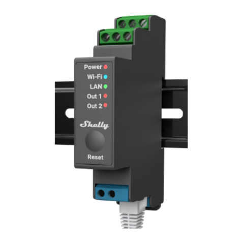
Shelly PRO 1 Installation and operating manual

USER AND SAFETY GUIDE
1 CIRCUIT WI-FI RELAY SWITCH
SHELLY PRO 1
Read before use
This document contains important technical and safety information about the
device, its safety use and installation.
⚠CAUTION! Before beginning the installation, please read this guide and any other
documents accompanying the device care fully and completely. Failure to follow the
installation procedures could lead to malfunction, danger to your health and life,
violation of the law or refusal of legal and/or commercial guarantee (if any). Allterco
Robotics EOOD is not responsible for any loss or damage in case of incorrect
installation or improper operation of this device due to failure of following the user
and safety instructions in this guide.
Product Introduction
Shelly® is a line of innovative microprocessor-managed devices, which allow remote
control of electric appliances through a mobile phone, tablet, PC, or home
automation system. Shelly® devices can work standalone in a local Wi-Fi network or
they can also be operated through cloud home automation services. Shelly®
devices can be accessed, controlled and monitored remotely from any place the
User has Internet connectivity, as long as the devices are connected to a Wi-Fi router
and the Internet. Shelly® devices have integrated web servers, through which the
user may adjust, control and monitor them. The cloud function could be used, if it is
activated through the web server of the device or the settings in the Shelly Cloud
mobile application. The user can register and access Shelly Cloud using either
Android or iOS mobile application, or with any internet browser at
https://my.shelly.cloud/ Shelly® Devices have two Wi-Fi modes - Access Point (AP)
1

and Client mode (CM). To operate in Client Mode, a Wi-Fi router must be located
within the range of the device. Devices can communicate directly with other Wi-Fi
devices through HTTP protocol. An API is provided by Allterco Robotics EOOD. For
more information, please visit:
https://shelly-api-docs.shelly.cloud/#shelly-family-overview
Control your home with your voice
Shelly® devices are compatible with Amazon Echo and Google Home supported
functionalities. Please see our step-by-step guide on:
https://shelly.cloud/support/compatibility/
Shelly® Pro Series
Shelly® Pro series is a line of devices suitable for homes, offices, retail stores,
manufacturing facilities, and other buildings. Shelly® Pro devices are DIN mountable
inside the breaker box, and highly suitable for new building construction. All Shelly®
Pro devices can be controlled and monitored through Wi-Fi and LAN connections.
Bluetooth connection can be used for the inclusion process.
Legend:
Device terminals:
• N: Neutral terminal
• L: Live (110-240V) terminal
• +12: 12V (10.5V to 13.5V) DC power supply terminal
• SW1: Switch (controlling O*) input terminal
• SW2: Switch* input terminal
• O: Load circuit output terminal
• I: Load circuit input terminal
Wires:
• L: Live (110-240V) wire
• L1(A): Load circuit live (110-240V) wire
• L2(B): Device power supply live (110-240V) wire
• +: 12 V DC power supply positive wire
• -: 12 V DC power supply negative wire
* Can be reconfigured
Installation Instructions
The Shelly Pro 1 smart relay (the Device) by Allterco Robotics EOOD is intended to
be mounted into a standard switchboard on DIN rail, next to the circuit breakers in
order to control the electric power through it . Shelly can work as a standalone device
or as an accessory to a home automation controller.
⚠CAUTION! Do not install the device at a place that is possible to get wet.
⚠CAUTION! Danger of electrocution. Mounting / Installation of the Device to the
power grid has to be performed with caution, by a qualified electrician.
2

⚠CAUTION! Danger of electrocution. Every change in the connections has to be done
after ensuring there is no voltage present at the Device terminals.
⚠CAUTION! Do not connect the Device to appliances exceeding the given max load!
⚠CAUTION! Use the Device only with a power grid and appliances which comply with
all applicable regulations. A short circuit in the power grid or any appliance connected
to the Device may damage the Device.
⚠CAUTION! Connect the Device only in the way shown in these instructions. Any
other method could cause damage and/or in jury.
⚠CAUTION! Тhe Device may be connected to and may control electric circuits and
appliances only if they comply with the respective standards and safety norms.
⚠RECOMMENDATION Connect the Device using solid single-core cables with
increased insulation heat resistance not less than PVC T105°C.
Connect the Device to the power grid and install it in the switch board as shown in
the schemes and following the Safety Instructions. Before starting
installing/mounting the Device, wire check that the breakers are turned off and there
is no voltage on their terminals. This can be done with a phase meter or multimeter.
When you are sure that there is no voltage, you can proceed to wiring the cables. If
you are using AC for the Device and the load circuit (fig.1), connect the N terminal to
the Neutral wire and the L terminal to the Device power supply circuit breaker.
Connect the 2 switch circuits to the S1 and S2 input terminals and the Device power
supply circuit breaker. Connect the load circuit to the O terminal and the Neutral wire.
Connect the I terminal to the load circuit breaker. Two different phases can be used
for the load circuit and the Device power supply circuit. If you are using AC to power
the Device, but want to switch a DC load circuit (fig.2), connect the N terminal to the
Neutral wire and the L terminal to the circuit breaker. Connect the 2 switch circuits to
the S1 and S2 input terminals and the circuit breaker. Connect the load circuit to the
O terminal and one of the load circuit power supply wires. Connect the I terminal to
the other load circuit power supply wire.
⚠CAUTION! The load circuit voltage should not exceed 30 V DC and the current
should not exceed 12 A.
If you are using 12 V DC to power the Device, but want to switch an AC load circuit
(fig. 3), connect the positive wire to the +12 terminal and the negative wire to the L
terminal. Connect the 2 switch circuits to the S1 and S2 input terminals and the
negative wire. Connect the load circuit to the O terminal and the Neutral wire.
Connect the I terminal to the circuit breaker. If you are using 12 V DC to power the
Device and want to switch a DC load circuit (fig. 4), connect the Device power supply
positive wire to the +12 terminal and the Device power supply negative wire to the L
terminal. Connect the 2 switch circuits to the S1 and S2 input terminals and the
Device power supply negative wire. Connect the load circuit to the O terminal and
one of the load circuit power supply wires. Connect the I terminal to the other load
circuit power supply wire.
⚠CAUTION! The load circuit voltage should not exceed 30 V DC and the current
should not exceed 12 A.
3

If you are using 12 V DC to power the Device, but want to switch an AC load circuit
(fig. 3), connect the positive wire to the +12 terminal and the negative wire to the L
terminal. Connect the 2 switch circuits to the S1 and S2 input terminals and the
negative wire. Connect the load circuit to the O terminal and the Neutral wire.
Connect the I terminal to the circuit breaker. If you are using 12 V DC to power the
Device and want to switch a DC load circuit (fig. 4), connect the Device power supply
positive wire to the +12 terminal and the Device power supply negative wire to the L
terminal. Connect the 2 switch circuits to the S1 and S2 input terminals and the
Device power supply negative wire. Connect the load circuit to the O terminal and
one of the load circuit power supply wires. Connect the I terminal to the other load
circuit power supply wire.
⚠CAUTION! The load circuit voltage should not exceed 30 V DC and the current
should not exceed 12 A.
⚠RECOMMENDATION For inductive loads, which cause voltage spikes during
switching, such as electrical motors, fans, vacuum cleaners, refrigerators and similar
ones, RC snubber (0.1µF / 100Ω / 1/2W / 600V AC) should be wired in parallel with the
load. RC snubbers can be purchased at
https://shop.shelly.cloud/rc-snubber-wifi-smart-home-automation.
Initial Inclusion
You can choose to use Shelly® with the Shelly Cloud mobile application and Shelly
Cloud service. Instructions on how to connect your device to the Cloud and control it
through the Shelly App can be found in the “App Guide” included in the box. You can
also familiarize yourself with the instructions for Management and Control through
the embedded Web interface at 192.168.33.1 in the Wi-Fi network, created by the
Device.
⚠CAUTION! Do not allow children to play with the button/ switch connected to the
Device. Keep the Devices for remote control of Shelly (mobile phones, tablets, PCs)
away from children.
Specifications
• Dry contact: Yes
• Power supply: 110-240 V AC, 50/60 Hz; 12V DC (DC range: +10.5 V ÷ 13.5 V,
250mA)
• Max switching current: 16 A
• DC output: 0 V ÷ 30 V; 12A
• Dimensions (HxWxL): 68.5x18.5x89.5 mm
• Mounting - DIN rail
• Wi-Fi - YES
• Bluetooth - YES
• LAN - YES
• Temperature Protection - YES
4

• Scripting (mjs) - YES
• MQTT - YES
• CoAP - No
• URL Actions - 20
• Scheduling - 50
• Add-on support - YES
• CPU - ESP32
• Flash - 8MB
• Operational range: (depending on terrain and building structure): up to 50 m
outdoors, up to 30 m indoors
• Electrical consumption: < 3 W
• Working temperature: 0°C - 40°C
• Controlled elements: 1 electrical circuit (max 30 V in DC mode).
• Controlling elements: 1 relay
• Radio signal power: 1mW
• Radio protocol: Wi-Fi 802.11 b/g/n
• Frequency Wi-Fi : 2412-2472 МHz; (Max. 2495 MHz)
• Frequency Bluetooth: TX/RX: 2402-2480 MHz (Max. 2483.5 MHz)
• RF output Wi-Fi: <20 dBm
• RF output Bluetooth: <5 dBm
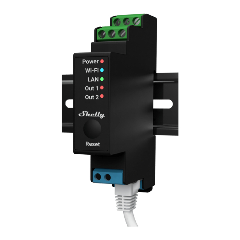
LED INDICATORS
Power (red): Red light indicator will be on if power is connected.
Wi-Fi (blue): Blue light indicator will be on if the Device is in AP mode.
Wi-Fi (red): Red light indicator will be on if the Device is in STA mode and not
connected to a local Wi-Fi network.
Wi-Fi (yellow): Yellow light indicator will be on if the Device is in STA mode and
connected to the local Wi-Fi network. Not con nected to Shelly Cloud or Shelly Cloud
disabled.
Wi-Fi (green): Green light indicator will be on if the Device is in STA mode and
connected to the local Wi-Fi network and to the Shelly Cloud.
Wi-Fi (flashing): The light indicator will be flashing Red/Blue if OTA update is in
progress.
LAN (green): Green light indicator will be on if LAN is connected.
Output (red): Red light indicator will be on if the Output relay is closed.
5

DECLARATION OF CONFORMITY
Hereby, Allterco Robotics EOOD declares that the radio equipment type Shelly Pro 1
is in compliance with Directive 2014/53/ EU, 2014/35/EU, 2014/30/EU, 2011/65/EU.
The full text of the EU declaration of conformity is available at the following inter net
address https://shelly.cloud/knowledge-base/devices/shelly-pro-1/
Manufacturer: Allterco Robotics EOOD
Address: Bulgaria, Sofia, 1407, 103 Cherni vrah Blvd. Tel.: +359 2 988 7435
E-mail: support@shelly.cloud
Web: http://www.shelly.cloud
Changes in the contact data are published by the Manufacturer at the official website
of the Device http://www.shelly.cloud
All rights to trademark Shelly® and other intellectual rights associated with this
Device belong to Allterco Robotics EOOD.
6

7

SHELLY MOBILE APPLICATION FOR
Introduction
Download the Shelly Cloud Application by scanning the QR code above, or access
the devices through the Embedded web interface, explained further down in the user
guide. Shelly devices are compatible with Amazon Echo and Google Home
supported functionalities, as well as other home automation platforms and voice
assistants. See details at https://shelly.cloud/support/compatibility/
Registration
The first time you load the Shelly Cloud mobile app, you have to create an account
which can manage all your Shelly devices. You need to use an actual e-mail because
that e-mail will be used in case of а forgotten password!
Forgotten Password
In case you forget or lose your password, click the “Forgot Password?” link on the
login screen and enter the e-mail used in your registration. You will receive an e-mail
with а link to а page where you can reset your password. The link is unique and can
be used only once.
First steps
After registering, create your first room (or rooms), where you are going to add and
use your Shelly devices. Shelly Cloud allows you to create scenes for automatic
control of devices at predefined hours or based on other parameters like
temperature, humidity, light, etc. (with upcoming add-ons or available sensors on
shelly.cloud. Shelly Cloud allows easy control and monitoring using a mobile phone,
tablet, or PC. Shelly Pro 1 can be grouped with other devices in the application. It
8

can also be set to trigger actions on other Shelly devices, run schedules, scenes, and
webhooks.
THE SHELLY APP
Abbreviations:
AP - Access Point. The mode in which the Device creates its own Wi-Fi network.
Device Inclusion:
Step 1
When the installation of Shelly Pro 1 is done and the power is turned on, Shelly will
create its own Wi-Fi Access Point (AP).
Step 2 Make sure the Location and Local Network for the Shelly Cloud app are
enabled in your phone settings. Please keep in mind that the inclusion process is
different for iOS and Android devices.
9

1. iOS inclusion - Select “Add device” from the hamburger menu on the top right of
your Shelly Cloud App. Enter your home network name and password, and click the
“NEXT” button. Select “Shelly Pro 1” from the dropdown list. A message will pop up
asking for your permission to connect to the AP of your Shelly Pro 1 (e.g
ShellyPro1-f008d1d8bd68). Click the “Join” button.
2. Android inclusion - Select “Add device” from the hamburger menu on the top right
of your Shelly Cloud App. Select your home network from the dropdown list and
enter its password. Next, you will see listed all of the available devices. Choose your
Shelly Pro 1 device from the list and click “Yes” when asked for inclusion. A
message will pop up asking for your permission to connect to your Shelly Pro 1’s AP
address (e.g. ShellyPro1-f008d1d8bd68). Click the “Yes” button.
10

Step 3
Once this process is completed, approximately 10 seconds later, a pop up (button)
will appear on the top of the page with “Discovered devices” on the home screen of
the Shelly Cloud App. click the “Discovered devices” button and find your Shelly
device in the list. If you do not see it, try again by clicking the “SCAN” button.
11

Step 4
You can choose which available device from the list to include. If a newer firmware
update is available, the app will first let you update and then add the device. Click
the “ADD DEVICE” button to move to the next step of the inclusion process.
Step 5
Enter a name for the device in the “device name” field. Select a room which the
device will be added to. For easy recognition of the device select an image from the
list of existing ones or upload your own. Click the “DONE” button.
12

Step 6
If you’d like to connect your device to the cloud and control it remotely, click “Yes”. In
case you want to control your devices only locally, click “No”.
Device settings
Once your Shelly Pro 1 is added to the Shelly Cloud, you can control it, change its
settings, and automate the way it works from any place where you have internet
connection. To switch the device on and off, use the ON/OFF button. For device
management, simply click on the device’s name. From there you may control the
device, as well as edit its appearance and settings.
Timer: Аllows you to manage the power supply automatically. You may use:
• Auto ON: After turning off, the relay output will be automatically turned on after a
predefined time (in seconds).
• Auto OFF: After turning on, the relay output will be automatically turned off after a
predefined time (in seconds)
Schedule: This function requires a working connection to the Internet. Shelly may
turn on/off automatically at a predefined need time and day throughout the week.
Additionally, Shelly may turn on/off automatically at sunrise/sunset, or at a specified
time before or after sunrise/sunset. You may add up to 20 weekly schedules.
Webhooks: Use events to trigger http endpoints. You can add up to 20 webhooks.
Internet:
• Wi-Fi 1: Allows the device to connect to an available Wi-Fi network. Enter the
network details in the respective fields and click the “APPLY'' button.
• Wi-Fi 2: Allows the device to connect to an available Wi-Fi network, as a secondary
(backup), if your primary Wi-Fi network becomes unavailable. Enter the network
details in the respective fields and click the “APPLY” button.
• Access Point: You can enable the device AP mode and change the password of
the Wi-Fi network created by Shelly Pro1. Click the “APPLY” button to enable the
device AP mode.
13

• Ethernet: Enable or disable Ethernet (LAN) connection. Changing this setting will
reboot the device.
• MQTT: Configure the Shelly device to communicate over MQTT.
• Cloud: Enables or disables the connection to Shelly Cloud. Connection to Shelly
Cloud allows you to control your device remotely and receive notifications and
updates.
Application Settings:
• PIN lock: Restrict control of the Shelly device through the web interface by setting
a PIN code. After typing the details in the respective fields, press “Restrict Shelly”.
• Sync name: Keep the device name in sync with the name given in the app.
• Input state Display: Turn on indicator for the current status of the physical switch
connected to Shelly Pro 1. When enabled, a small line appears under the power
button icon. A red line indicates the physical switch is off, while a green line indicates
the physical switch is on.
• Exclude from Event Log: Do not show events from this device in the app.
• Share: Share the control of your device with other Shelly Cloud users.
Settings:
• Input/Output Settings: These settings define the way the attached switch or button
controls the output state. The possible input modes are “button” and “switch”.
• Invert switch: If enabled, the device will consider the switch is on, while it is
actually switched off and vice versa.
• Device Name: Set a name for your device.
• Firmware version: Shows your current firmware version. If a newer version is
available, you can update your Shelly device by clicking Update.
• Geo Location And Time Zone: Set your timezone and geo-location manually, or
enable/disable automatic detection.
• Device Reboot: Reboot your Shelly Pro 1.
• Factory Reset: Remove Shelly Pro 1 from your account and return it to its factory
settings. This will delete all set data.
• Device Information: Here you can view the ID, IP and other settings of your device.
Upon clicking “Edit device”, you can change the room, name or image of the device.
THE EMBEDDED WEB INTERFACE
If your Shelly Pro 1 is in AP (Access Point) mode, connect your PC or mobile device
to the Wi-Fi network with the name (SSID) such as ShellyPro1-f008d1d8bd68. Enter
http://192.168.33.1 into the address field of your browser to load the web interface
14

of Shelly Pro 1. If you can’t find the Shelly Pro 1 AP, it may already be connected to
your home WI-Fi network and its AP mode disabled. Find your Device IP address in
the Wi-Fi network. You can use a simple tool to find shelly devices in the local
network: https://shelly.cloud/documen ts/device_finders/ ShellyFinderWindows.zip
(Windows) and https://shelly.cloud/documents/device_finders/
ShellyFinderOSX.zip (Mac OSX). Enter the device IP address into the address field of
your browser to load the web interface of Shelly Pro 1. If you can’t find the Shelly Pro
1 AP or its IP address in your home Wi-Fi network, you can enable the AP mode by
pressing and holding the device Reset button for 5 seconds.
GENERAL- HOME PAGE
In the home page of the Shelly Pro 1 Web Interface, you can monitor the device
status, check different settings, and switch on/ off the device relay. The device
connection status is displayed in the header bar between the logo and the time.
• Gray AP icon indicates the AP mode is disabled. Blue AP icon indicates the AP
mode is enabled.
• Gray Wi-Fi icon indicates the Wi-Fi connection is disabled. White Wi-Fi icon
indicates the Wi-Fi connection is enabled, but not established. Blue Wi-Fi icon
indicates the device is connected to a Wi-Fi network.
• Gray Bluetooth icon indicates the Bluetooth connection is dis abled. Blue Bluetooth
icon indicates the Bluetooth connection is enabled.
• Gray cloud icon indicates the connection to Shelly Cloud is disabled. White cloud
icon indicates the connection to Shelly Cloud is enabled, but not established. Blue
cloud icon indicates the device is connected to Shelly Cloud.
• Gray LAN icon indicates the LAN connection is disabled. White LAN icon indicates
the LAN connection is enabled, but not established. Blue LAN icon indicates the
device is connected to a LAN.
• Gray Mqtt icon indicates the Mqtt is disabled. Blue Mqtt icon indicates that Mqtt is
enabled.”
Clicking on an icon takes you to the corresponding settings.
Channel settings
• Input output settings: Select button or switch input mode. Set how the relay
behaves in response to the button or switch input, as well as relay output default
state when the device is powered on.
• Invert switch: If enabled, the device will consider the switch is on, while it is
actually switched off and vice versa. • Channel name: Enter a custom name for the
channel. Default one is “switch_0”.
• Consumption type: Select the type of the appliance(s) controlled by this device. Will
15

be used for grouping, filtering, consumption calculations in Shelly Cloud with future
features.
Timers
Аllow you to manage the power supply automatically. You may use:
• Auto ON: After turning off, the relay output will be automatically turned on after a
predefined time (in seconds).
• Auto OFF: After turning on, the relay output will be automatically turned off after a
predefined time (in seconds).
Schedules
This function requires a working connection to the Internet. Shelly may turn on/off
automatically at a predefined need time and day throughout the week. Additionally,
Shelly may turn on/off automatically at sunrise/sunset, or at a specified time before
or after sunrise/sunset. You may add up to 20 weekly schedules.
Webhooks
Use events to trigger http endpoints. You can add up to 20 web hooks.
Device:
• SNTP server: Synchronizes a computer’s system time with a server. Default is set
to time.google.com
• Device Name: Set a name for your device.
• Firmware version: Shows your current firmware version. Allows you to check if a
newer version is available and update your Shelly device.
• Location: Set your city and time zone.
• Device Reboot: Reboot your Shelly Pro 1.
• Factory Reset: Remove Shelly Pro 1 from your account and return it to its factory
settings. This will delete all set data.
• Authentication: Set credentials to lock your device or change already existing
credentials.
• Debug: Allows the debugging log to be viewed through MQTT, Websocket, or UDP.
• Map input: Choose which button/switch input controls the output.
Networks
• Wi-Fi 1: Allows the device to connect to an available Wi-Fi network. Enter the
network details in the respective fields and click the “APPLY” button.
• Wi-Fi 2: Allows the device to connect to an available Wi-Fi network, as a secondary
16

(backup), if your primary Wi-Fi network becomes unavailable. Enter the network
details in the respective fields and click the “APPLY” button.
• Access Point: You can enable the device AP mode and change the password of
the Wi-Fi network created by Shelly Pro1. Click the “APPLY” button to enable the
device AP mode.
• Ethernet: Enable or disable Ethernet (LAN) connection. Changing this setting will
reboot the device.
• Cloud: Enables or disables the connection to Shelly Cloud. Connection to Shelly
Cloud allows you to control your device remotely and receive notifications and
updates.
• Bluetooth: Enables or disables Bluetooth connectivity.
• MQTT: Configure the Shelly device to communicate over MQTT.
Scripts
Shelly Pro devices feature scripting capabilities. Scripts enhance significantly the
number of tasks that can be solved using Shelly devices. You can find more at
https://shelly-api-docs.shelly.cloud/gen2/ Scripts/ShellyScriptLanguageFeatures/
17
Table of contents
Other Shelly Switch manuals
Popular Switch manuals by other brands

TRENDnet
TRENDnet TEG-S4000 Specification sheet

Allied Telesis
Allied Telesis x950 Series installation guide

TP-Link
TP-Link TL-SG105E installation guide

NETGEAR
NETGEAR FS108 - ProSafe 10/100 Desktop Switch installation guide

Siemens
Siemens SITRANS L Series operating instructions

Gilat
Gilat SkyEdge II-c Capricorn PLUS Installation notes

Bühler technologies
Bühler technologies Nivotemp NT 61 Brief instructions

Albalá Ingenieros
Albalá Ingenieros AVP1221C01 manual

LEGRAND
LEGRAND Pro 21 7756 21 instruction manual

Cisco
Cisco MEM-S2-512MB= notes Installation notes

Bühler technologies
Bühler technologies Nivotemp NT M-L Brief instructions

Pilz
Pilz PSEN cs1.13p operating manual