Shenzhen Hongdian Technologies H9380P User manual
1

2
Shenzhen Hongdian Technologies Corporation provides customers with a full range of technical
supports, and the users can contact headquarter of Hongdian directly.
Shenzhen Hongdian Technologies Corporation
Address Tower A, Hongdian Building, 100 Huabao Road, Pinghu, Longgang
District, Shenzhen, China
Website http: //www.hongdian.com
Technical
Support +86-755-88864288-5
Fax Number +86-755-83404677
Email sales@hongdian.com

3
Contents
1 Product Introduction ....................................................................................... 4
1.1 H9380P............................................................................................................. 4
1.1.1 Front panel............................................................................................ 4
1.1.2 Rear panel ............................................................................................. 4
1.1.3 Side panel.............................................................................................. 5
1.1.4 Specifications ........................................................................................ 5
2 Installation ..................................................................................................... 9
2.1 Unpacking and attachment inspection ............................................................ 9
2.2 The introduction of serial port......................................................................... 9
2.3 LVDS signal interface.........................................................错误!未定义书签。
2.4 LVDS backlight interface....................................................错误!未定义书签。
3 Use of device.................................................................................................10
3.1 Installation check ........................................................................................... 10
3.2 Powering on and off the device ..................................................................... 10
4 Use of device ...............................................................................................11
4.1 Power-on operation....................................................................................... 11
4.2 Audio video service........................................................................................ 11
4.3 Self-starting APP business.............................................................................. 11
4.4 Serial peripheral............................................................................................. 11
4.5 USB peripheral ............................................................................................... 12
5 Daily maintenance.........................................................................................10
4
1 Product Introduction
1.1 H9380P
1.1.1 Front panel
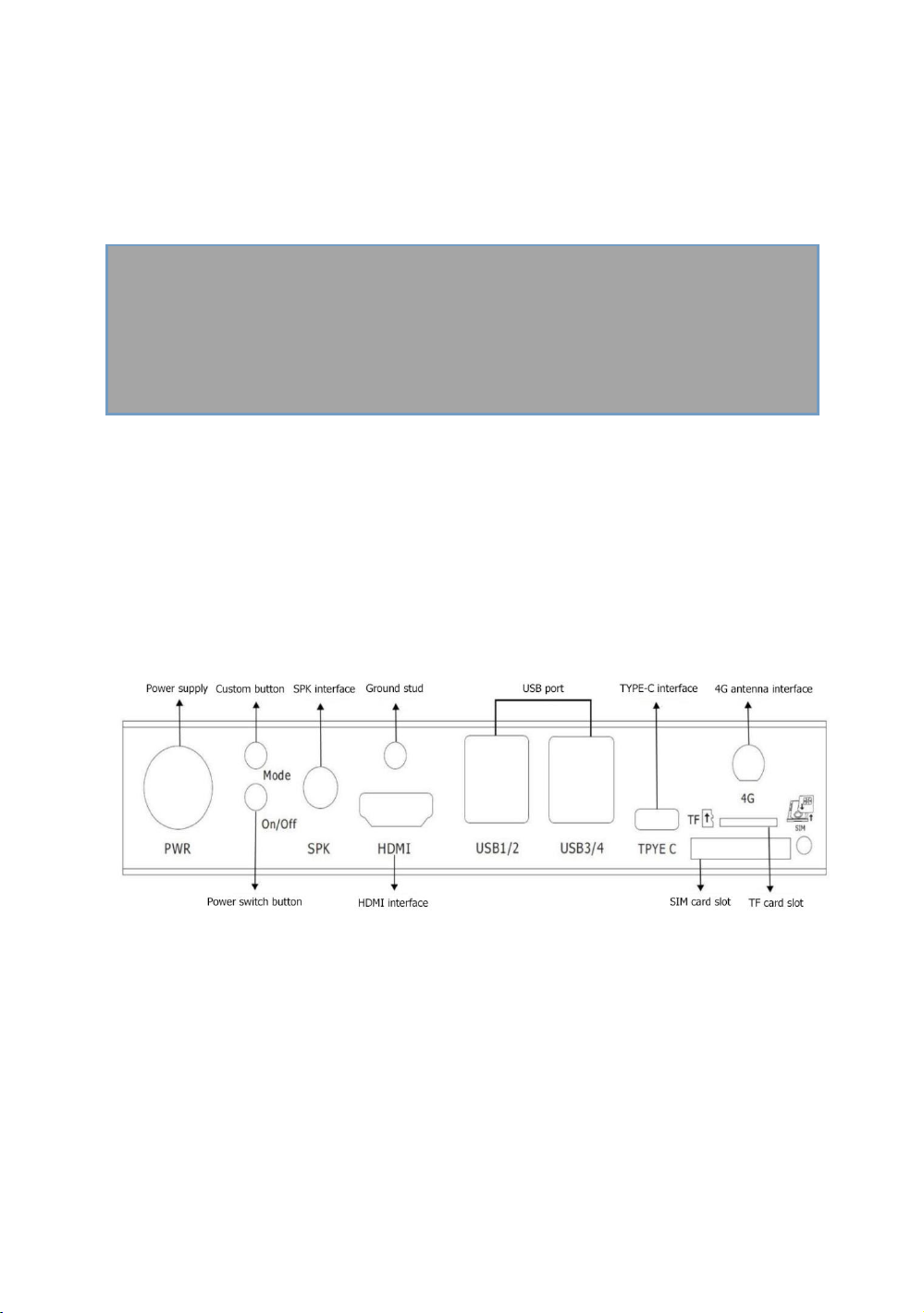
1.1.2 Rear panel
5
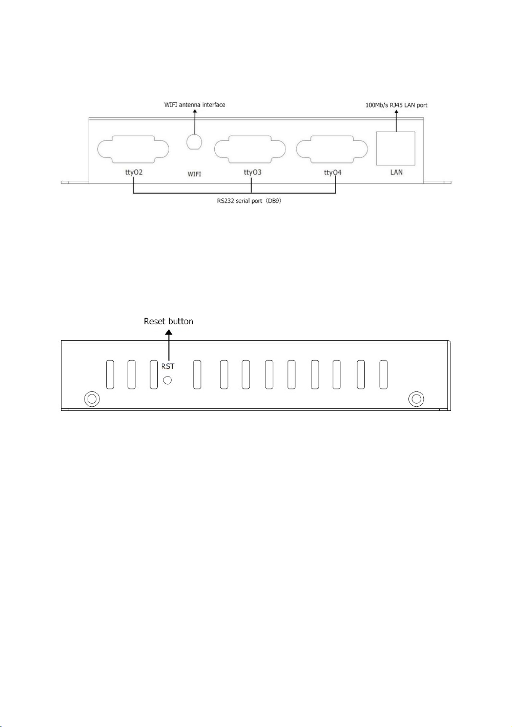
1.1.3 Side panel
1.1.4 Specifications

6
Interface
Number of
interfaces Introduction
H9380P
4Pin power connector 1 Used to power the device
Custom button 1
Used to return to the previous level, exit from
the main APP and enter maintenance mode and
other functions
Power switch button 1 Used to control device switches
Reset button 1 For device reset
Ground stud 1 For grounding
WIFI antenna interface 1 Used to enhance WIFI signals
4G antenna interface 1 For receiving signals
TYPE C interface 1 Used for data transfer between the device and
the PC
SIM card slot 1 For placing a SIM card
TF card slot 1 For placing TF cards
USB port 4 Used to connect USB peripherals and upgrade
100Mb/s RJ45 LAN port 1 Used to connect network cables
HDMI interface 1 Used to connect to the HDMI display
LVDS interface
(extended support) NULL Used to connect Signal line of LVDS display
MIC interface NULL For external microphone devices
SPK interface 1 For external speaker equipment
Audio port NULL For external microphone devices (supports
three-stage audio plug)
RS232 serial port(DB9) 3 For data communication (1 multiplexing;
default RS232, RS485 optional)
3pin terminal (RS485) NULL For data communication
Indicator light 4 Used to display the working status of the device

7
Indicator status table
Indicator
light description Status
power
supply
PWR
Power off the device Extinguished
Power on the device Constantly bright
Network
light
4G
Dialing was not successful(Module not found
/Module is dialing) Extinguished
4G/3G/2G dialing succeeded Constantly bright
Signal light
SIG
No dialing, no signal or weak signal (less than 4
cells) Fast flashing
Signal full (signal strong) Constantly bright
WiFi/SYS
light
System startup or system exception without
self-starting APP Extinguished
The system is running normally,and the
self-starting APP is normal.
Slow flashing(Lighted up for
0.25s,extinguished for 0.75s)
The system is running normally, and the
self-starting APP is abnormal.
Slow flashing(Lighted up for 0.25s,
extinguished for 1.75s)
The system is running normally, there is no
self-starting APP
Slow flashing(Lighted up for
0.25s,extinguished for 3.75s)
Open Wifi station mode and connect
successfully Constantly bright
Wifi off or Wifi not connected Extinguished
PS:The number of cells of the signal light corresponds to the signal grid in the upper right corner of the
display (full grid is 4 grids).
U disk / TF card upgrade status table
During the upgrade process All indicators except the power supply flash slowly (Lighted up for 0.25s,

8
extinguished for 1.75s)
Successful upgrade All indicators except the power supply are always on
Failed upgrade All indicators except the power supply flash quickly(Lighted up for
0.25s,extinguished for 0.25s)
9
2 Installation
2.1 Unpacking and attachment inspection
Please check the device for deformation or other damage after unpacking.If there is any discrepancy,
please contact the supplier immediately.A packing list is included in the box. Please check the integrity of
all accessories of the equipment according to this list.
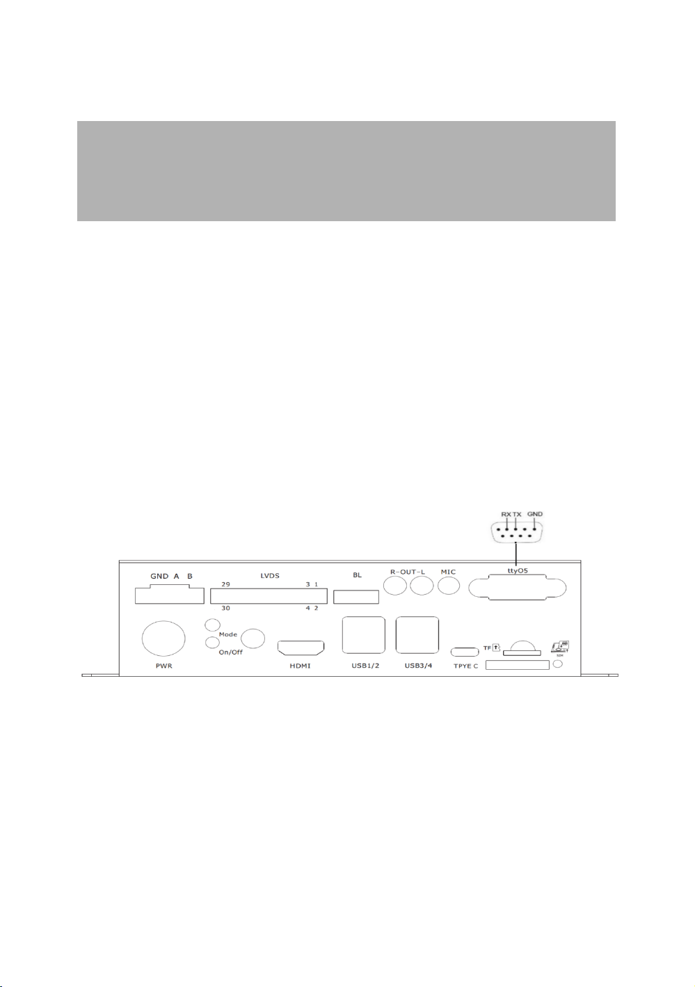
2.2 The introduction of serial port
The serial port of the IPC device of the H9380P series is shown in the following figure.The H9380P device
has three sets of RS232 interfaces with DB9 structure (the wiring mode is the same as the tty05 interface
in the figure below).

1
3 Use of device
3.1 Installation check
Is the SIM card and TF card plugged in tightly.
Whether the serial port and network port on the panel are tight.
Check if the 3G/4G antenna and WIFI antenna on the panel are loose.
Check if the audio and video connectors are loosely connected.
Check if the connection of each USB peripheral is loose.
3.2 Powering on and off the device
Use the power adapter specified by the device (standard 12V/2A power adapter).
Check the status of the indicator when the device is powered on. Refer to the indicator status table
on page 05.Observe whether the display can open the self-starting APP interface normally,and you
can open it to start normal operation.
When the device is in maintenance,you need to power off the device when the device is powered
on to prevent damage to the SIM card,TF card,and peripherals.

1
4 Use of device
4.1 Power-on operation
Powering on the device and the power indicator (PWR) is steady on,indicating that the device is powered
on successfully.After 20-30 seconds,the system/self-starting APP indicator (SYS/APP) lights up every 4
seconds,indicating that the device is operating normally.
4.2 Audio video service
According to the business needs to connect HDMI or LVDS display, you can use one screen or two screens
to display the output separately or simultaneously.The output can be displayed normally,indicating that
the audio and video services are normal.
PS:If you need to use a customized touch screen,you need to provide the touch screen driver, or PID,VID
number to our company.After writing to the system, we can use the touch screen normally.
4.3 Self-starting APP business
By configuring an APP as a monitoring APP in the Settings-Auxiliary Function-Primary and Secondary
APP,it is set as a self-starting primary APP or secondary APP.When the device is powered on,the device
will actively set the main APP as a self-starting APP,which will be automatically started on the
display,displayed at the forefront,and the secondary APP will run in the background.The self-starting APP
can be displayed normally, that is,the self-starting APP service is normal.When you need to debug the
device,you can press the custom button to return to the desktop for debugging.After five minutes,the
self-starting app will be pulled up again.
4.4 Serial peripheral
If you need to use serial interface peripherals (such as QR code scanning head, printer,motor driver
board),you need to match the serial port node name of each serial port peripheral with the serial port
node name of our serial port to communicate normally.
4
44

1
4.5 USB peripheral
If you need to use a general-purpose USB peripheral such as a mouse and keyboard,you can plug and
playif;you need to use special USB peripherals (such as USB printer,ID card),you need to provide USB
driver, or PID,VID number for us, it can be used normally after writing to the system.

17
5 Daily maintenance
Keep the equipment ventilated and dry. Do not stack other objects at will, keep the equipment
away from heat, dust and strong magnetic fields.
Make sure that the equipment is not wet or damaged when in the field or in an open field.
To ensure the insulation of the device from the contact, the user must not touch live objects to the
device.
Do not replace any modules and components on the device while the device is powered.
Do not open or disassemble the equipment without the guidance of our professional staff.

17
Table of contents
Other Shenzhen Hongdian Technologies Industrial PC manuals


