Shenzhen Sailwider Electronics Co., Ltd. RCS-Z31C Owner's manual

Shenzhen Sailwider Electronics Co., Ltd.
Page
1
of
15
Product Specification
Sailwider
Wireless Energy Ethernet Gateway
(RCS-Z31C)
Shenzhen Sailwider Electronics Co., Ltd.
Page
2
of
15
1. General introduction of RCS-Z31C Wireless Energy Ethernet Gateway.
The Sailwider Wireless Energy Ethernet Gateway builds the wireless energy monitoring system into the
Ethernet platform and links the energy management system with Ethernet network system (IEEE802.3).
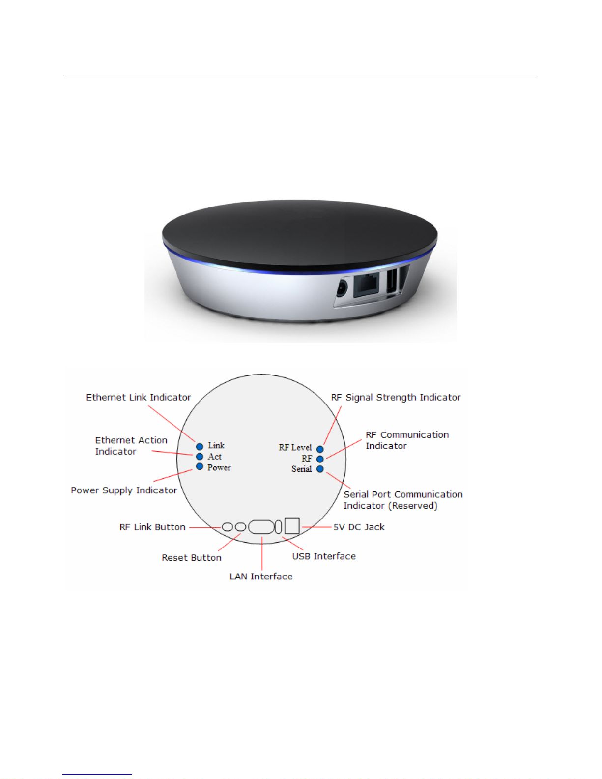
1.1 Appearance Design
1.2 Interfaces, Buttons and LED indicators
LED Indicator descriptions:
•Link This indicator lights up when Ethernet network link is established.
•Act This indicator flashes when there is data flow in the Ethernet network.
•Power This indicator lights up when the gateway is powered on.
•RF Level This indicator lights up when the RF signal is strong, flashes when signal is weak and lights off when
there is no signal. If there are two or more than two transmitters paired with the gateway, this
indicator will represent the weakest signal’s strength.
•RF This indicator flashes when RF wireless communication is in process.

Shenzhen Sailwider Electronics Co., Ltd.
Page
3
of
15
•Serial This indicator flashes when there is data flow in the serial port (reserved).
Interface and Buttons descriptions:
•DC 5V The DC Jack for power supply.
•USB The USB port for power supply (Also reserved for serial devices).
•LAN The Ethernet network interface. 10/100 Base-T RJ45 interface to connect with network router.
•Reset Press this button to recover the factory default setting. To reset or to clear all paring, history data and web
server setting, press the Reset Button and hold it here for 5 seconds until the right 3 LED indicators all light
up, then release the Reset Button, after 2 seconds, the right 3 LED indicators all light off and all information
hasbeencleared.Be cautious to use this button since all data will be lost.
•RF Link This button is used to pair the sensor terminals with the gateway.
2. Installation and Operation of the wireless energy Ethernet gateway.
2.1 Installation Preparation
Power Supply: 100-240VAC, 50/60 Hz
Working Temperature: -10-50℃
Working Humidity: 10-90%, with no condensation.
2.2 Installation and Pairing
2.2.1 Power on the gateway and connect it with home Ethernet network.
1) Use the power adapter to connect the gateway’s DC jack with the main power supply until the
power indicator lights up. Or use a USB power adapter to provide power via the gateway’s USB
interface until the Power LED indicator lights up.
2) Plug Ethernet network cable into the LAN interface of the gateway and connect it with a local
working router or home wall network socket, wait until the Link LED indicator lights up, which means
the Ethernet network link has been established.
3) The sensor terminals that can be paired with the gateway include the 1-way power transmitter with
sensor clamp (or LED sensor), temperature transmitter, 2-way sensor socket & 2-way RF switch.
2.2.2 To pair a 1-way power transmitter with the gateway:
1) Keep the power transmitter as close to the gateway as possible. Pull out the clear plastic tab
(marked with “REMOVE BEFORE USING”) from the back of the transmitter. The tab is an insulation
sheet, once it is pulled out, the built-in batteries will make the transmitter start to work immediately.
2) Press the RF link button of the gateway and hold it there for about 5 seconds until the RF indicator
lights up, then the gateway enters the pairing mode and begins to search for pairing signal.

Shenzhen Sailwider Electronics Co., Ltd.
Page
4
of
15
3) Now use a slim stick to push into the pairing hole of the transmitter (as shown in below photo) and
hold it there for about 3 seconds until the LED light of the transmitter flashes quickly. Then release
the slim stick and the transmitter is now starting to pair with the gateway.
4) The pairing may take up to 60seconds. When the pairing is successfully finished, the RF indicator of
the gateway will flash and the gateway automatically exits the pairing mode. The user will see the
transmitter information on the web page. If the gateway can’t receive a pairing signal from a
transmitter in 60 seconds, it will also exit the pairing mode automatically. While the transmitter will
exit the pairing mode after sending pairing signal for 30seconds.
5) Each transmitter has its own MAC ID and after successful pairing, the gateway will regard it as
authorized device and handle its wireless data in the gateway to the distant server.
6) The user may choose to use the embedded web server on the gateway or distant server to add or
delete transmitters.
7) Up to 10 sensor terminals totally can be paired with the gateway.
2.2.3 To pair a 2-way sensor socket with the gateway:
The remote control function is realized via the 2-way sensor plug sockets, which connect the electrical
appliances into the system by working between the appliances and the power supply. The 2-way sensor
plug sockets work as the sensor terminals and detect the power consumption data from the appliances.
It also receives and implements the switching on/off instruction remotely from the gateway. To make the
sensor plug socket communicate with the gateway, it need to be paired with the gateway first.
1) Before pairing, keep the sensor socket closest to the gateway. Try to locate a power supply wall
socket nearest to the gateway. Attach the sensor plug socket into the power supply socket and
switch on the sensor socket by pressing its switch button.

Shenzhen Sailwider Electronics Co., Ltd.
Page
5
of
15
2) Press the RF link button of the gateway and hold it there for about 5 seconds until the RF indicator
lights up, then the gateway enters the pairing mode and begins to search for pairing signal.
3) Now use a slim stick to push into the pairing hole of the sensor plug socket and hold there for about
6 seconds until the LED light on the sensor plug socket flashes quickly. The sensor socket is now
starting to pair with the gateway. The pairing may take up to 60 seconds. When the pairing is
successfully finished, the LED light on the sensor socket will stop flashing and the RF indicator of
the gateway begins to flash. And the user can see the sensor socket information on the web page. If
the gateway can’t receive a pairing signal in 60 seconds, it will also exit the pairing mode
automatically. While the sensor socket will exit the pairing mode after sending pairing signal for
60seconds.
4) After the pairing is finished, pull out the sensor socket from the power supply socket near the
gateway and attach it again to the power supply socket near the actual electrical appliance to be
monitored and controlled, then attach the plug of the electrical appliance into the sensor plug socket.
And the connected electrical appliance can now be monitored and controlled via the gateway
remotely.
5) Each sensor socket has its own MAC ID and after successful pairing, the gateway will regard it as
authorized device and handle its wireless data in the gateway to the distant server.
6) The user may choose to use the embedded web server or distant server to add or delete the sensor
sockets.
7) Up to 10 sensor terminals totally can be paired with the gateway.
2.2.4 To pair a 2-way RF switch with the gateway:
The RF switch is the 2-way sensor terminal mainly used for lightings or for appliances that don’t have a
power plug. It detects the power consumption data from the lightings (appliances). It also receives and
implements the switching on/off instruction remotely from the gateway. But its installation is not so simple
as the sensor socket.
1) Before pairing, keep the RF switch closest to the gateway. Since the RF switch is installed on the
power line, so if not able to keep it closer, then just keep it where it is.
2) Press the RF link button of the gateway and hold it there for about 5 seconds until the RF indicator
lights up, then the gateway enters pairing mode and begins to search for pairing signal.
3) Now use a slim stick to push into the pairing hole of the RF switch and hold there for about 6
seconds until the LED light on the RF switch flashes quickly. The RF switch is now starting to pair
with the gateway. The pairing may take up to 60 seconds. When the pairing is successfully finished,

Shenzhen Sailwider Electronics Co., Ltd.
Page
6
of
15
the LED light on the RF switch will stop flashing and the RF indicator of the gateway begins to flash.
And the user can see the RF switch information on the web page. If the gateway can’t receive a
pairing signal in 60 seconds, it will also exit the pairing mode automatically. While the RF switch will
exit the pairing mode after sending pairing signal for 60seconds.
4) After the pairing is finished, the connected lights (or electrical appliance) can now be monitored and
controlled via the gateway remotely.
5) Each RF switch has its own MAC ID and after successful pairing, the gateway will regard it as
authorized device and handle its wireless data in the gateway.
6) The user may choose to use the embedded web server or distant server to add or delete the RF
switches.
7) Up to 10 sensor terminals totally can be paired with the gateway.
2.2.5 To pair a temperature transmitter with the gateway:
The temperature transmitter uses the same case as the 1-way power transmitter. Please pair the
temperature transmitter in the same way as the 1-way power transmitter.
2.3 Configuration and management of embedded web server
When the gateway has been properly connected with the ADSL router (Act LED indicator flashes), the
router will assign a dynamic IP address to the gateway via DHCP. Use a PC in the same LAN and open
the browser on the PC, input the gateway’s device name directly in the url address bar, in the format of
http://ses001 (ses001 is the default device name and can be changed by the user), then tap the enter key
to visit the embedded web sever. The basic setting page of the embedded server will display as below:

Shenzhen Sailwider Electronics Co., Ltd.
Page
7
of
15
1) Device Name: The default name is SES001. The user can change it to desired name (its maximum
length is 15 characters and it should not contain empty space or symbols not accepted to be url). The
device name can be used as the URL address to visit the embedded web server in browser in the
format of http://devicename. Please keep record of the changed device name, otherwise the user will
not be able to log in the web server and have to reset to factory setting, which will lose all data.
2) Server URL (IP): This is the address of the distant server where the gateway needs to transmit data
to and receive command from. For example, a url address http://www.xxxxx.com or an ip address
192.168.1.x. Please use the real IP address or url address of the distance server. If required, please
also set the port number of the distant server. The setting range of the port is 1-65535.
After this setting, the gateway will automatically link the distant server and send data to the distant
server in Client mode according to set interval.
Note: Customer can ask us to set the server URL (IP) and Port number into the factory setting.
3) DHCP: The default setting is , means the router will assign a dynamic IP address to the
gateway and the user will be able to view the IP address (not settable). To allow IP setting by hand,
please select , and the user will be able to set the parameters as below photo:
Fill in the columns the IP address of the gateway. Please don’t use the same IP address
of other device in the same LAN. This IP address should be in the same network segment as the LAN
gateway.
Please set the correct subnet mask of the LAN here.
Please set the correct gateway address for connection with outside network here.
Please set the correct DNS here.
4) Fill in this column the time interval of data sending from the gateway
to the distant server. The default setting is 120seconds.
5) : Please check above setting correctly, then click the “save” button to save the setting. And
the gateway will reboot and refresh the setting.
6) Time running setting: Please refer to below description:
Shenzhen Sailwider Electronics Co., Ltd.
Page
8
of
15
The default setting is allow NTP server Yes, which means the device synchronizes the time with NTP
server every 24 hours. The user can change the NTP server then click the “Sync to Device” button to
synchronize.
The user may choose No to synchronize the gateway’s clock with local PC instead of distant timing
server. Please just click “Sync to Device” button. Upon power cut off, the gateway’s time will return to
default time: Jan. 1st, 2012.
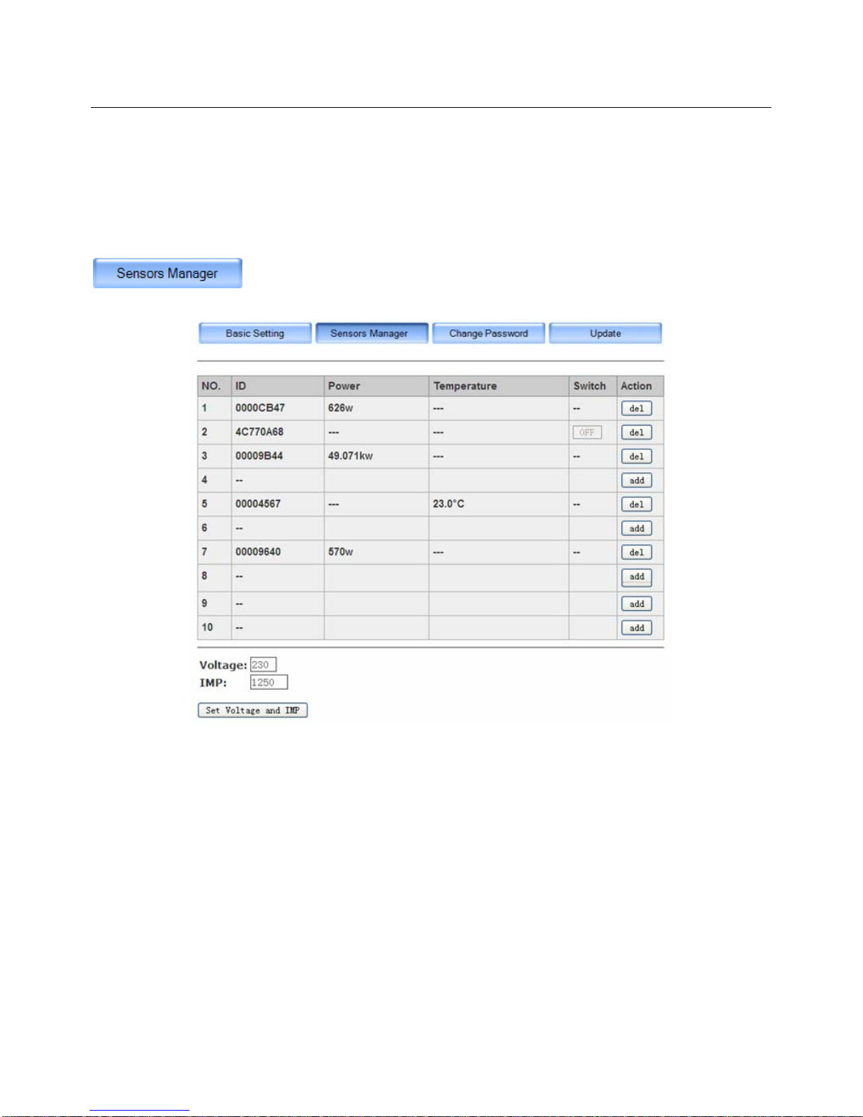
Please click the Sensors Manager button to enter the interface of sensors management, as below:
This page is used to add or delete the sensor terminals and to view the real time power data of each
1-way transmitter (with clamp or LED sensor), 2-way sensor sockets, 2-way RF switches or temperature
transmitters. The user can also operate the switch on/off function from this page for the 2-way sensor
terminals. When the real time power is larger than 999w, its unit will automatically change to be kw.
The voltage for the 1-way transmitter with clamp or the IMP value for the 1-way transmitter with LED
sensor also needs to be set here.
If the transmitter is a temperature transmitter, its temperature can be read from this page in the column of
“Temperature”. The temperature can be displayed is -30℃to 50℃. For temperature out of this range, it
will display as “LO” if less than -30℃and will display as “HO” if higher than 50℃.
To add a new sensor terminal into the system from the embedded web server, click the “add” button on a
blank line, then the gateway will enter the pairing mode. Then operate the same way on the sensor
terminals as described in 2.2 Installation and Pairing to pair sensor terminals with the gateway. When

Shenzhen Sailwider Electronics Co., Ltd.
Page
9
of
15
the gateway receives the pairing signal from the sensor terminals, its sensors manager page will
automatically display the sensor’s MAC ID and real time data. The gateway will send the received real
time data to the distant server according to the set interval. Its “add” button changes to be “del” button. For
2-way sensors, there is a button ON or OFF appearing in its “Switch” column.
To delete a sensor terminal from the system, please simply click the button on the same line.
For 1-way transmitter with clamp or LED sensor, the voltage and IMP value need to be set correctly in this
page, otherwise the data can’t be correct.
Please input the correct value and click the “Set Voltage and IMP” button to save the setting. This setting
has nothing to do with the 2-way sensor terminals since they detect both voltage and current. The setting
range for the voltage is 0-999. The setting range of the IMP is 0-9999.
The factory setting of the user name is “admin” with blank password. The user can change the user name
and password here.
Once the user has changed the password setting, next time he need to login with correct user name and
password to visit the web server.

Shenzhen Sailwider Electronics Co., Ltd.
Page
10
of
15
The user should keep the user name and password properly, otherwise the user will not able to login the
web server and has to reset to factory setting to visit the web server. In this case, all data will be lost. The
user needs to do the pairing and setting again.
The gateway can be upgraded here once the user has the upgrade file in the computer. Save the upgrade
file in local PC.
To upgrade the energy gateway
Please browse and select the upgrade file, then click the “Update” button.
During the upgrading, the right three LED indicators will flash in cycle. When they stop flashing, the
upgrade is finished. During the upgrading, don’t cut off the power.
After the upgrading, please do the reset. In this case, all data will be lost. The user needs to do the pairing
and setting again.
To upgrade the web pages of the embedded web server on the gateway
Please also browse and select the upgrade file, then click the “Update” button.
When below window pops up, click “Site main page” to return to the web pages and finish the upgrading.
In case both the energy gateway and the embedded web pages need to be upgraded, make sure to
upgrade the energy gateway first.
3. Installation of the 1-way Power Transmitter, Sensor Clamp and LED sensor
The 1-way power transmitter is with 2pcs C batteries inside. It uses sensor clamp or LED sensor to collect
the energy consumption data.All sensor clamps and LED sensor are detachable.
The sockets on the transmitter for each CT and LED sensor are displayed as below photo.

Shenzhen Sailwider Electronics Co., Ltd.
Page
11
of
15
If sensor clamp is to be used, make sure that the voltage has been set correctly. Plug the sensor clamp
into any one of the three CT sockets.
Place the transmitter near the input trunk cables for home (usually under the electricity meter). Fix the
Sensor Clamp around the live wire or the null wire of the input trunk cables for the home. Make sure to let
the wire pass through the clamp.
The Sensor Clamp immediately starts to detect the current and the transmitter sends the data to the
gateway which will send the received data to the distant server according to set time interval. The user will
begin to be able to see the real time data of home energy consumption on the distant server or the
embedded web server.
Under single phase power supply, one transmitter can work on up to three objects by using 3pcs sensor
clamps fixed around the live wire or the null line of each object (if they are close enough to the transmitter).
Then the data of the transmitter is the total data of three objects.
The transmitter can be put flat in a dry place nearby or be stuck on the wall nearby using the 3M velcro on
its back.
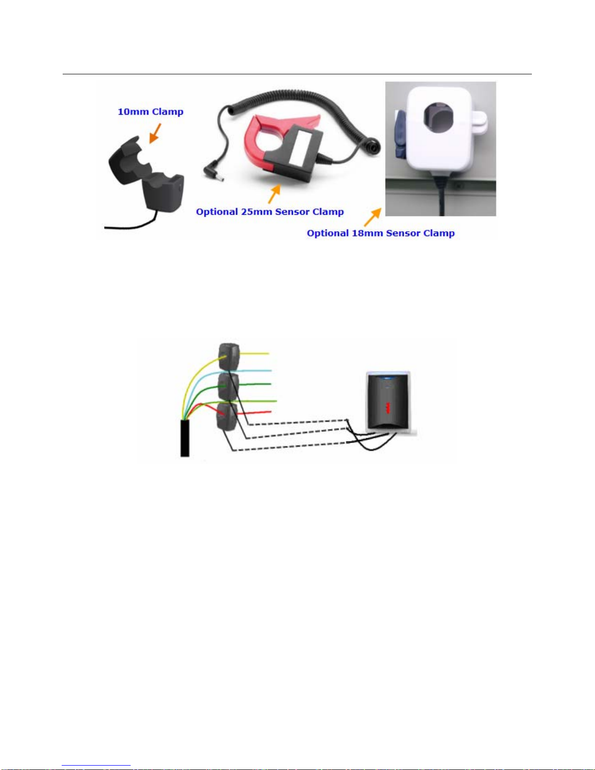
Note: We have three kinds of optional sensor clamps for different diameter wire: 10mm, 18mm and 25mm.
Each transmitter can be used for only one kind of sensor clamp. So please check the mark on the
transmitter to make sure that correct size sensor clamps are being used.
Shenzhen Sailwider Electronics Co., Ltd.
Page
12
of
15
3-phase power supply
If the monitoring target is 3-phase, the user needs totally three sensor clamps for the transmitter. Attach
the DC plug of each sensor clamp into the three CT sockets on the bottom of the Transmitter. Fix the 3pcs
of Sensor Clamps around the lines of Phase-A, Phase-B and Phase-C (Don’t fix the clamps around the
ground wire and neutral wire).
LED Sensor
In case the user does not require the LED sensor to collect data from the meter, please ignore this step.
The LED sensor reads data directly from the meter and calculates the energy consumption by the IMP
pulse flashing.
To install the LED sensor on the transmitter, just plug the DC plug of the LED sensor to its socket (IMP) on
the bottom of the transmitter. Once the LED sensor is plugged in, the sensor clamp will stop working.
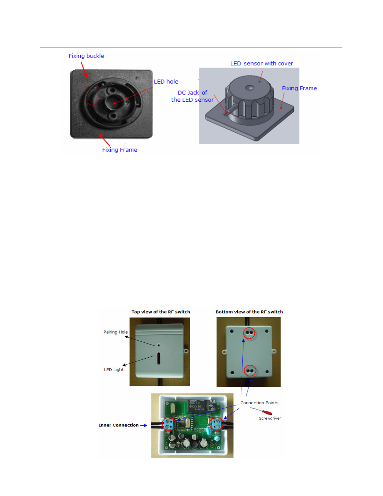
The sensor side is installed on the meter. Please refer to below photo, the back of the fixing frame is with
3M sticker. Stick the fixing frame on the meter, make sure the LED hole is just in the position of the IMP
pulse flashing window of the meter.
It’s very important not to allow outside light to interfere the LED sensor since this will seriously
affect the measurement accuracy.
Then put the LED sensor with cover on the fixing frame and turn it around clockwise until the position is
secured.
Shenzhen Sailwider Electronics Co., Ltd.
Page
13
of
15
When using LED sensor for the measurement, please make sure that the IMP/KWH of the meter has
been correctly set on the gateway.
4. Installation of the 2-way sensor socket
The installation of the 2-way sensor socket is quite simple. Just first plug it into a wall socket near the
target appliance, then plug the appliance into it.
5. Installation of the 2-way RF switch
The RF switch is the 2-way sensor terminal mainly used for lightings. It can be used for one light or a
group of lights or for appliances that don’t have a power plug. It detects the power consumption data from
the lightings. It also receives and implements the switching on/off instruction remotely from the gateway.
The installation of the 2-way RF switch needs to be done by an electrician. Please decide where to install
the RF switch to monitor and control, then follow below photo regarding the installation.
Shenzhen Sailwider Electronics Co., Ltd.
Page
14
of
15
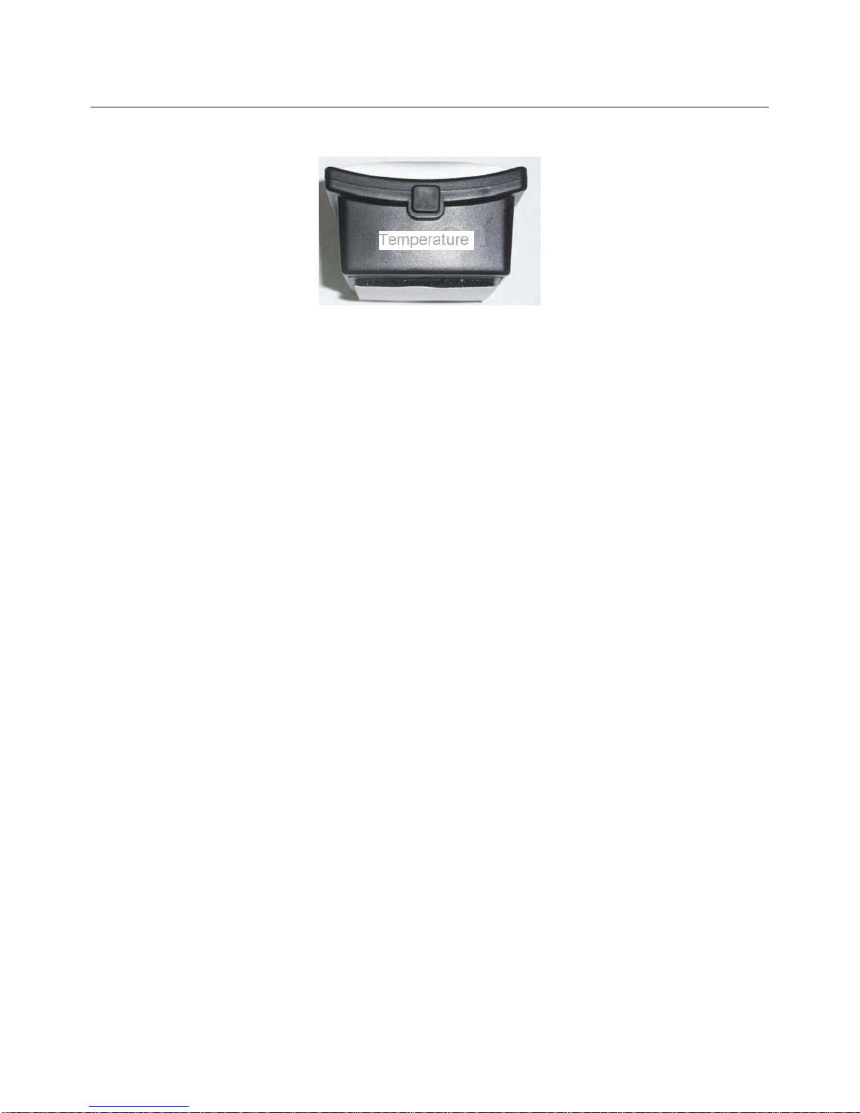
6. Installation of the temperature transmitter
The temperature transmitter uses the same case as the 1-way power transmitter, but without the sockets
for the CT or LED sensor. After pairing, the transmitter can be flat in a dry place or be stuck on the wall
using the 3M velcro on its back in the environment to be measured.
7.FCC STATEMENT
1. This device complies with Part 15 of the FCC Rules, Operation is subject to the following two
conditions:
(1) This device may not cause harmful interference.
(2) This device must accept any interference received, including interference that may cause undesired
operation.
2. Changes or modifications not expressly approved by the party responsible for compliance could void
the user’s authority to operate the equipment.
NOTE:
This equipment has been tested and found to comply with the limits for a Class B digital device, pursuant
to Part 15 of the FCC Rules, These limits are designed to provide reasonable protection against harmful
interference in a residential installation.
This equipment generates uses and can radiate radio frequency energy and, if not installed and used in
accordance with the instructions, may cause harmful interference to radio communications.
However, there is no guarantee that interference will not occur in a particular installation. If this equipment
does cause harmful interference to radio or television reception, which can be determined by turning the
equipment off and on, the user is encouraged to try to correct the interference by one or more of the
following measures:
- Reorient or relocate the receiving antenna.
- Increase the separation between the equipment and receiver.
- Connect the equipment into an outlet on a circuit different from that to which the
receiver is connected.
- Consult the dealer or an experienced radio/TV technician for help.

Shenzhen Sailwider Electronics Co., Ltd.
Page
15
of
15
Thank you for reading this user manual and using our product.
www.sailwider-smartpower.com
Table of contents


