Shenzhen VDWALL Co., Ltd. LVP919 Series User manual
SHENZHEN VDWALL CO.,LTD www.videowall.cn
1
Add: Room B, 5th Floor, Bldg.C, Tongfang Information Harbor, Nashan Hi-Tech Park, Nanshan District, Shenzhen
Tel: +86-755-2675 0210 / 2650 1506 / 2663 6668
Marketing QQ:400-0660-628 Technical QQ Group:422024594
LVP919 Series
LED VIDEO WALL PROCESSOR
USER MANUAL V1.0
LVP919 SERIES USER MANUAL Contents
2
Contents

LVP919 SERIES USER MANUAL Chapter 1 Safety Precarious
3
Chapter 1 Safety precautions
Danger
There exists high voltage in the processor, in order to prevent any unexpected hazard, please do not open
the cover of the device unless you are a maintenance.
Warning
1. This device shall not encounter water sprinkle or splash, please do not place anything containing water
on this device;
2. Keep this device away from any fire source to prevent fire;
3. If this device gives out any strange noise, smoke or smell, please unplug the power cord from receptacle
immediately, and contract local dealer;
4. Signal cables are hot swappable.
Caution
1. Please thoroughly read this manual before using this device, and keep it well for future use;
2. Please pull the power plug out of receptacle while lighting or you are not going to use the device for a
long time;
3. Nobody other than professional technicians can operate the device, unless they have been
appropriately trained or under guidance of technicians;
4. Please do not fill in anything in the vent of the device in order to prevent equipment damage or electric
shock;
5. Do not place the device near water or anywhere damp;
6. Do not place the device near any radiator or anywhere under high temperature;
7. Please handle and keep them properly to prevent any rupture or damage of power cords;
8. Please immediately unplug power cord and have the device repaired, when:
1Liquid splashes to the device;
2The device is dropped down or cabinet is damaged;
3Obvious malpractice is found or performance degrades.

LVP919 SERIES USER MANUAL Chapter 2 Packing List
4
Chapter 2 Packing list
Please unpack the product carefully, then check whether all the following things are included in the
package. If anything is missing, please contact the dealer.
Standard accessories
The accessories supplied with this LED Video Processor may differ from the figures on the User’s
Manual, but they are applicable for the regions where you live.(LED sending card is optional)
1.5m power cord * 1
1.5m DVI cable * 1
0.5m DVI cable * 4
1.5m USB cable * 1
Operation CD * 1
User manual * 1
BNC-RCA adapter * 2
PCB audio adapter * 2
LVP919 SERIES USER MANUAL Chapter 3 Hardware Connection
5
Chapter 3 Hardware Connection
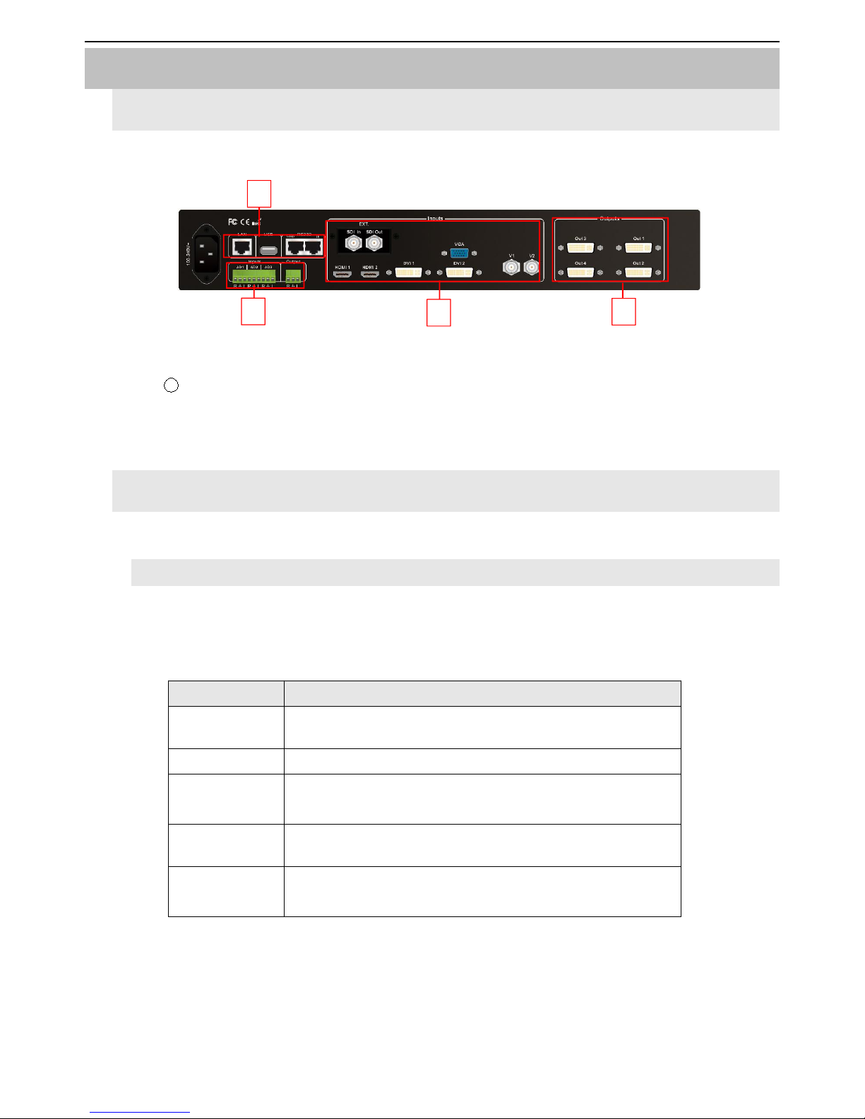
1.Diagram of signal ports on rear panel
1
4
4
3
Pic 3-1 Diagram of signal ports on rear panel
1Video input port ② DVI output port ③ Communication port ④ Audio port
2.Ports description
1). Inputs
LVP909 supports 8 video input signals as follows:
Ports
Description
V1、V2
2 channels of Composite video input (PAL/ NTSC)
VGA
1 channel of PC analog signal input
DVI1、DVI2
2 channels of DVI digital inputs (compatible with HDMI 1.3
inputs)
HDMI1、HDMI2
2 channels of HDMI digital inputs (HDMI 1.3)
EXT.
1 channel of extended input(SDI/HD-SDI/3G-SDI is an
optional input)

LVP919 SERIES USER MANUAL Chapter 3 Hardware Connection
6
2). DVI Outputs
Ports
Description
DVI1、
DVI2、
DVI3、
DVI4
4 channels of DVI output port to connect LED sending
cards or monitors.
3). Communication ports
Ports
Description
LAN
TCP/IP local area network control interface
USB
USB Communication port
RS232 In
Serial communication interface, connected to PC through
RS232 port to realize PC software control
RS232 Out
Serial communication output cascading, RS232 LEV, it can
control several processors by only one PC

LVP919 SERIES USER MANUAL Chapter 3 Hardware Connection
7
3. Hardware connection diagram
Pic 3-3a LVP919 Hardware connection diagram
LVP919 SERIES USER MANUAL Chapter 3 Hardware Connection
8
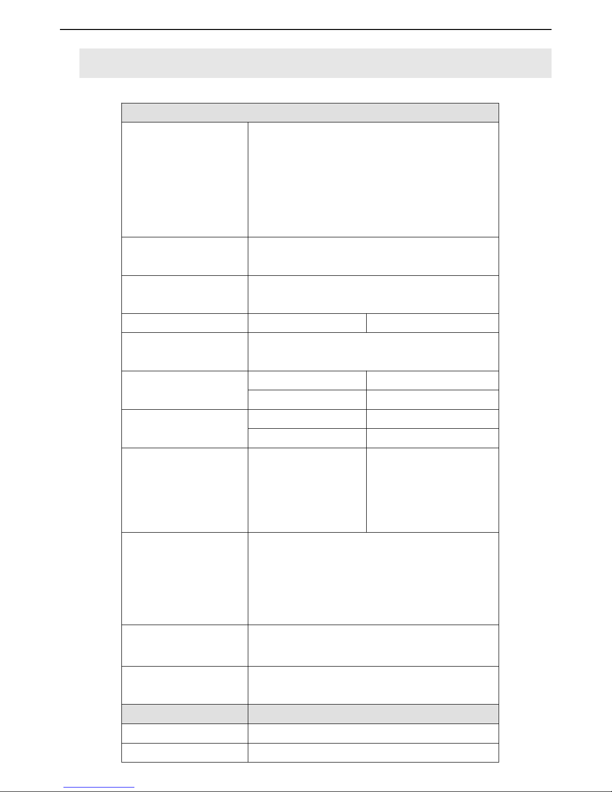
4. Technical specification
Specification of Inputs
Quantity / Type
2×CVBS
1×VGA(RGBHV)
2×DVI(VESA / CEA-861)
2×HDMI(VESA / CEA-861)
1×SDI(HD-SDI / 3G-SDI)(Optional)
Composite Video Input
SYS
PAL / NTSC
Composite Video
Amplitude Impedance
1V(p_p)/ 75Ω
VGA Format
PC(VESA Standard)
≤1920×1200_60Hz
VGA Amplitude the
impedance
R、G、B = 0.7 V(p_p)/ 75Ω
DVI Format
PC(VESA Standard)
≤1920×1200_60Hz
HDMI1.3(CEA-861)
≤1080p_60Hz
HDMI Format
PC(VESA Standard)
≤1920×1200_60Hz
HDMI1.3(CEA-861)
≤1080p_60Hz
SDI Format
SMPTE259M-C
SMPTE 292M
SMPTE 274M / 296M
SMPTE 424M / 425M
480i_60Hz
576i_50Hz
720p、1080i、1080p
Input Interface
CVBS:BNC
VGA:15pin D_Sub (Female)
DVI:24+1 DVI_D
HDMI:Type-A HDMI port
SDI:BNC / 75Ω
Type/Quantity of Audio
Outputs
Analogous Dual Audio Channel x3+(HDMI with
embedded audio)
Audio Amplitude the
Impedance
2.0Vp-p/10KΩ
Specification of Outputs
Quantity / Type
16 x DVI
DVI Format
1024 x 768_60Hz

LVP919 SERIES USER MANUAL Chapter 3 Hardware Connection
9
1280 x 1024_60Hz
1440 x 1440_60Hz
1920 x 1080_50Hz
1920 x 1080_60Hz
1920 x 1200_60Hz
Output Interface
DVI OUT:24+1 DVI_D
Type/Quantity of Audio
Outputs
Analogous Dual Audio Channel x1
Load Impedance of Audio
Outputs
70mW/32Ω or 105mW/16Ω
Others
Control Port
RS232 / USB / LAN
Voltage of Input
100-240VAC 50 / 60Hz
Power Consumption
≤35W
Temperature of
Environment
0-45℃
Humidity of Environment
15-85%
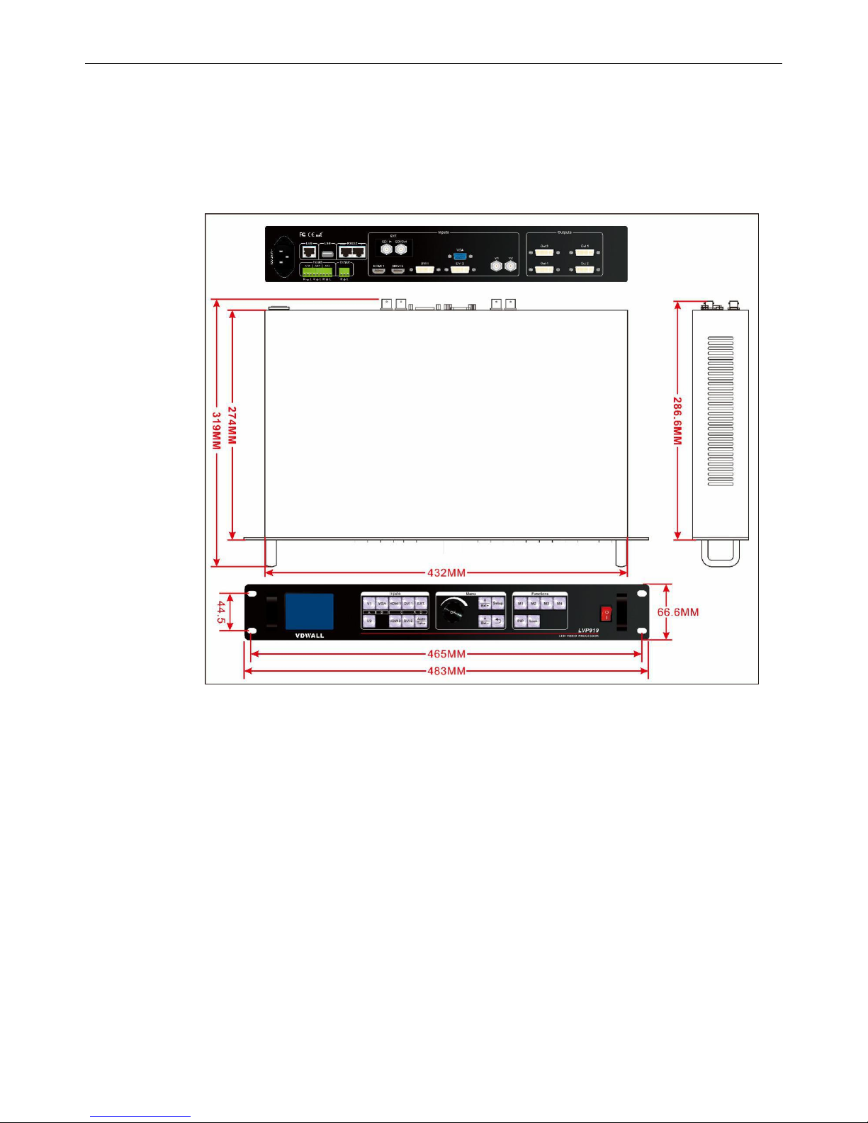
Size of Product
482.6(L)x274(W)x66.6(H)mm
Packing Size
535(L)x400(W)x145(H)mm
Weight
G.W.:5.6Kg, N.W.:3.7Kg
LVP919 SERIES USER MANUAL Chapter 3 Hardware Connection
10
Product Dimensions:
Pic 3-4a LVP919 Product Dimensions

LVP919 SERIES USER MANUAL Chapter 3 Hardware Connection
11
RS232 cable order:
Pic 3-4b RS232 converted to RJ45 cable order

LVP919 SERIES USER MANUAL Chapter 4 Description for Front Panel Buttons
12
Chapter 4 Description for front panel buttons
1. Sketch map of front panel buttons
1
2
3
3
3
Pic 4-1 Sketch map of front panel buttons
1Selection buttons of input signals ② Setup buttons ③ Other function buttons
1). Selection buttons of input signals
Selection buttons of input signals are used for selecting input signals.
V1、V2、VGA、DVI1、DVI2、HDMI1、HDMI2、EXT.
Take:switch from current signal to the pre-select signal under Pre.+Take switching mode.
2). Setup buttons
Setup buttons:set images output parameters。
Setup、↑、↓、Knob、
Setup:Enter the setup menu
↑、↓:Select setup options
Knob:Knob this button to adjust values or parameters
OK:Press this button to save parameters
:Return to the previous item
Auto:Can be used to switch the current outputs while it is on outputs parameter menu.
3).VGA auto-adjustment buttons
VGA auto-adjustment buttons (Auto): Adjust VGA input signals automatically.
LVP919 SERIES USER MANUAL Chapter 4 Description for Front Panel Buttons
13
4).Brightness adjustment buttons
Brightness adjustment buttons(Brt+,Brt-):Adjust the output brightness of video processors.
5).PIP function buttons
PIP: Turn on/off the function “picture in picture”or “picture by picture”. When the indicator is on,
that means this function is ready.
Knob:Knob and press it to switch PIP Mode when PIP is on.
6).Splice mode buttons
Splice mode buttons(M1,M2,M3,M4):call and set the display modes, call splice modes, call PIP
modes on PIP menu.
7).Lock button
Lock button(Lock):lock all buttons. When lock is on. The red light will be on all the time. The other
buttons are not available the Lock button. Press Lock button for 3 times without stop to unlock this
function, the red light is off.
8).Information button
On the state of switching channel, knob it and check the input and output parameters of all the
interfaces, press OK to check the current settings and information of LVP919.
LVP919 SERIES USER MANUAL Chapter 5 Instructions of Basic Operations For Users
14
Chapter 5 Instructions of basic operations for users
After LVP919 is powered on, LVP909 will automatically detect the device information and enter the user
operating status before shutdown last time including switching status, PIP/POP status, parameter, etc. We
would describe it on usual basic operations below.
1.Selection from input signals
LVP909 supports two sorts of signal switching way including one key switch and Pre.+Take switch
which can be set in user setup menu 3.1 switch mode. One key switch is the default switching mode.
Switch to a new signal by pressing input signals selection buttons. Pre.+Take switch adopts to press
input signal buttons to preselect and then press TAKE button to switch from current input signal to
preselect signal.
The input signals selection buttons are as the follow form:
Buttons
Description
V1、V2
2 channels of Composite video input (PAL/ NTSC)
VGA
1 channel of PC analog signal input
DVI1、DVI2
2 channels of DVI digital inputs (compatible with
HDMI 1.3 inputs)
HDMI1、HDMI 2
2 channels of HDMI digital inputs (HDMI 1.3)
EXT.
1 channel of extended input(SDI/HD-SDI/3G-SDI
is an optional input)

LVP919 SERIES USER MANUAL Chapter 5 Instructions of Basic Operations For Users
15
1)One key switch
LCD screen shows as following pictures:
Input:HDMI1
In status:1080p_60Hz
--------------------------------------
Out1 Out Pos.&Size:(0, 0, 1920, 1080)
Out1 In Pos.&Size: (0, 0, 1920, 1080)
--------------------------------------
Switch Mode:One Key SW
Pic 5-1a LCD display interface
LCD shows the current selected input signal source on the first row after selecting the input
signal, such as: HDMI. LCD shows the status of the current selected input signal source on the
second row, if there is no input signal source, it will show “No effective inputs”, and the indicator
flash at the same time. If there do exist an effective input signal, then it will show the input format,
such as:“ 1080p_60Hz ” .
2)Pre.+Take
LCD screen shows as following pictures:
Curr. Input:HDMI1
Curr. In Status:1080p_60Hz
Pre. Input:V1
Pre. In Status:PAL
--------------------------------------
Out1 Out Pos.&Size:(0, 0, 1920, 1080)
Out1 In Pos.&Size: (0, 0, 1920, 1080)
--------------------------------------
Switch Mode:Pre. +Take SW.
Pic 5-1b LCD display interface

LVP919 SERIES USER MANUAL Chapter 5 Instructions of Basic Operations For Users
16
Signal switching method:firstly press the input buttons to preselect the input signal, and the
LCD screen will show you the current input signal and the preselected input signal, then switch the
input signal between them by pressing Take button, after switching, the preselected input signal
becomes the current input signal. If the indicator flashs quickly, it means there exist a input signal,
otherwise, there is no input signal.
Attention :Pre.+Take switch is a seamless switching, we can select one input signal among
these 4 groups of input signals unless they belong to the same group. For example: if the current
input signal is V1(V1 belongs to Group A), you can only choose one input signal from Group B,
Group C or Group D, the groups are as follows:
A
B
C
D
V1、V2
VGA
DVI1、DVI2、HDMI1、
HDMI2
EXT.
3)Switching time selection
We can realize seamless switching among the 4 groups of input signals unless they belong to
the same group. The switching effect includes 0 second fast seamless switching, 0.5 second 、1
second、1.5 second fade in and fade out switching, we can enter Menu 3.2 to select the option to
choose switching time.
Cut:switching time: 0 second, it is the default switching effect of LVP919。
Fade:switching time: 0.5 second、
1.0 second or 1.5 second. you can realize fade in and fade
out switching among these 4 groups of input signals.

LVP919 SERIES USER MANUAL Chapter 5 Instructions of Basic Operations For Users
17
2.Operations on PIP mode
It is permitted to insert a PIP window on LVP919, this PIP input signal can be any non-grouped input
signals (grouped input signals are as follows on page 18). The position and size of these dual image can
be set into 4 modes. The detailed operations are as follows:
Enter the dual picture display mode:press PIP button and the indicator is on, enter the dual
picture display mode, then you can press buttons to select the PIP input signal. The LCD screen will
show you what the main input signal and PIP input signal is and the position and size of the
corresponding image.(As follows)
Main Input:HDMI1
Main In Status:1080p_60Hz
PIP Input:V1
PIP In Status:PAL
--------------------------------------
Main Pos.&Size: (0, 0, 1920,540)
PIP Pos.&Size: (0, 540,1920,540)
PIP Mode:M1
Pic 5-2a LCD display interface
Change the PIP input:press the corresponding button to select a input signal and this selected
input signal is the PIP input.
Change the main input :press those buttons to select the main input signal after pressing PIP
button and close PIP mode. Then press PIP button and select the PIP input signal.
Switching PIP mode:when dual picture mode is on, you can knob to switch the PIP mode, and
press OK to switch to the pointed display mode.
LVP919 SERIES USER MANUAL Chapter 5 Instructions of Basic Operations For Users
18
3. Call mosaic application mode
LVP919 can preset four mosaic display modes, press mode buttons (M1,M2,M3,M4 )to call
mosaic modes directly.
4.Other basic operations
1)Output brightness selection(Brt+, Brt-)
LVP919 supports 32-level output brightness settings. In order to ensure the integrity of the
output image grayscale, the output brightness is usually set to 32!
Buttons
Description
BRT-
To reduce output brightness, the lowest is 0
BRT+
To increase output brightness, the highest is 32
2)VGA input auto adjustment ( Auto )
When LVP919 is under one-key directly switching mode, the current input source is a valid VGA
input signal, press Auto to enable the LVP919 to automatically adjust the sampling parameters of
the VGA input signal, making the VGA image clear and complete.
This operation is usually performed only when a new VGA source is connected. The
auto-adjustment time changes depending on the condition of the input signal source, and usually
does not exceed 1 minute. sometimes it’s may necessary to perform this automatic adjustment
several times until the VGA screen is clear, complete, and stable.

LVP919 SERIES USER MANUAL Chapter 5 Instructions of Basic Operations For Users
19
3)Check system information ( OK )
On the user interface, when PIP is off, knob it and you can check the input and output
parameters of each port in order.
Input:HDMI1
In Status:1080p_60Hz
--------------------------------------
Out1 Out Pos.&Size:(0, 0, 1920, 1080)
Out1 In Pos.&Size: (0, 0, 1920, 1080)
--------------------------------------
Switch Mode:One Key SW.
Pic 5-4a LCD display interface
In the signal switching state, press OK to display the current settings and information of
LVP919.
System Info
--------------------------------------
Model:Lvp919
Version:V0.0.8
IP:192.168.1.8
Mask:255.255.255.0
Gate:192.168.1.1
Mac: 76-64-77-00-00-00
Resolution: 1920x1080_60Hz
Pic 5-4b LCD display interface

LVP919 SERIES USER MANUAL Chapter 5 Instructions of Basic Operations For Users
20
System Info
--------------------------------------
Input:V0.0.8
Output:V0.0.8
Pic 5-4c LCD display interface
System Info
--------------------------------------
Made Data:2018-07
Pic 5-4d LCD display interface
Table of contents
Other Shenzhen VDWALL Co., Ltd. Computer Hardware manuals

Popular Computer Hardware manuals by other brands


Dynavector
Dynavector SSP-5 Operation manual

StarTech.com
StarTech.com 8STECUSB3S254F instruction manual

ASROCK Rack
ASROCK Rack EPC621D8A Quick installation guide

ICP Electronics
ICP Electronics Celeron ROCKY-3701 manual

Phonic
Phonic i4800 user manual

Texas Instruments
Texas Instruments Tiva C Series Development guide


